This blog was created to memorialize the building process of my Van's Aircraft RV-14 and to satisfy the requirements for certification in the Experimental Amateur Built Aircraft category. It will also serve as a central location for ME to reference in the future on processes and techniques I used during the build. Additionally, it will allow my family, friends, and other interested builders the opportunity to follow along during my build…..and might be helpful to someone along the way.
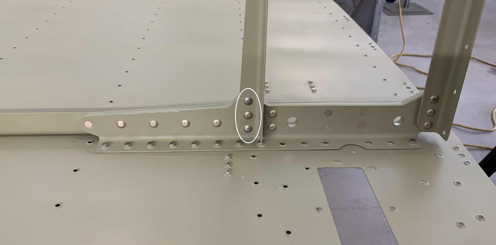
During the last work session, I riveted the Aft Gear Brace Assembly to the Center Bottom Skin. Today, I will rivet the F-01416B-L & -R Seat Rib Angles. Below is the right side of the Assembly showing the manufactured heads of the single AN470AD4-7 rivet (on the top) and the two AN470AD4-8 rivets on the bottom.
Here is the aft right side showing the shop heads.....
.....left forward side manufactured heads.....
.....left aft side shop heads.
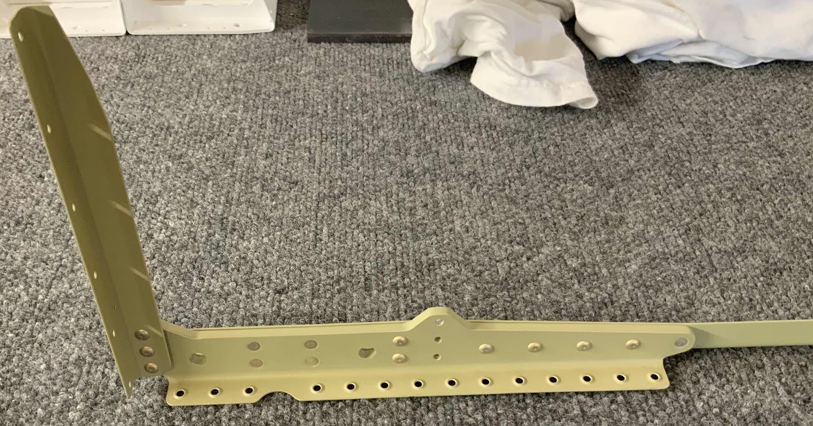
Prior to riveting the Angles to the Aft Gear Braced Assembly, the plans advised to make sure the F-01416B Seat Rib Angles and the F-01415A Seat Rib Angles are parallel with one another. To do this, I used a ruler to verify the same measurements at the top and bottom of the Angles. The lower measurement is 9 7/8” as shown below.....
.....and 9 7/8” at the top. Once those measurements were made, the Angles were clamped to the Assembly, one of the rivets was partially set, re-checked the measurement, and then completely set the rivet. I completed the same process for the remaining two rivets.
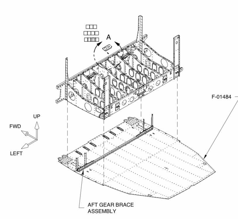
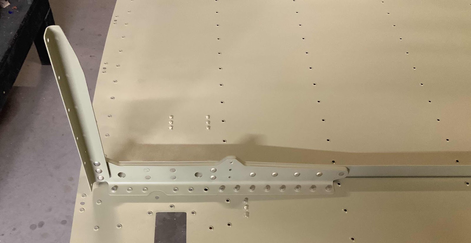
After this was completed, the F-01404 Bulkhead was clecoed to the F-01484 Center Bottom Skin as shown in the plans excerpt below.
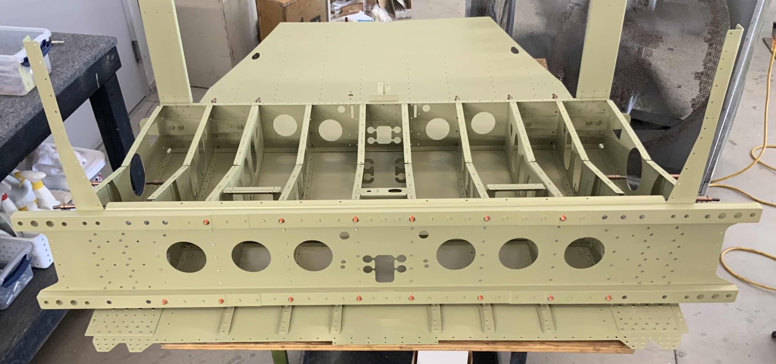
Shown below is the final assembly of the Aft Gear Brace Assembly. There are four parts that make up the Assembly:
1. F-01448A Gear Brace Angle
2. F-01448B Gear Brace Bar
3. F-01448C Gear Brace Brackets
4. F-01415A Seat Rib Angles
The Assembly was first clecoed together to allow several holes to be #30 final-drilled, 1/8 final-drilled, dimpled #30, and countersunk. Once all that was completed, the Assembly was riveted together using a mixture of AN470AD4-7 and AN426AD4-7 rivets. Here is the forward side of the Assembly showing the manufactured heads.....
.....and the aft side showing the shop head side of the rivets. The rivets were very easily set using my pneumatic squeezer and produced perfect results.
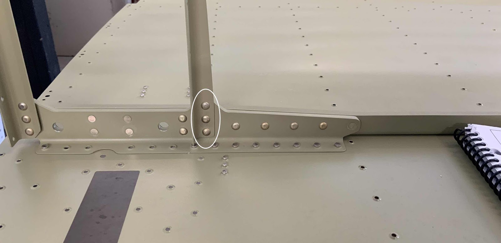
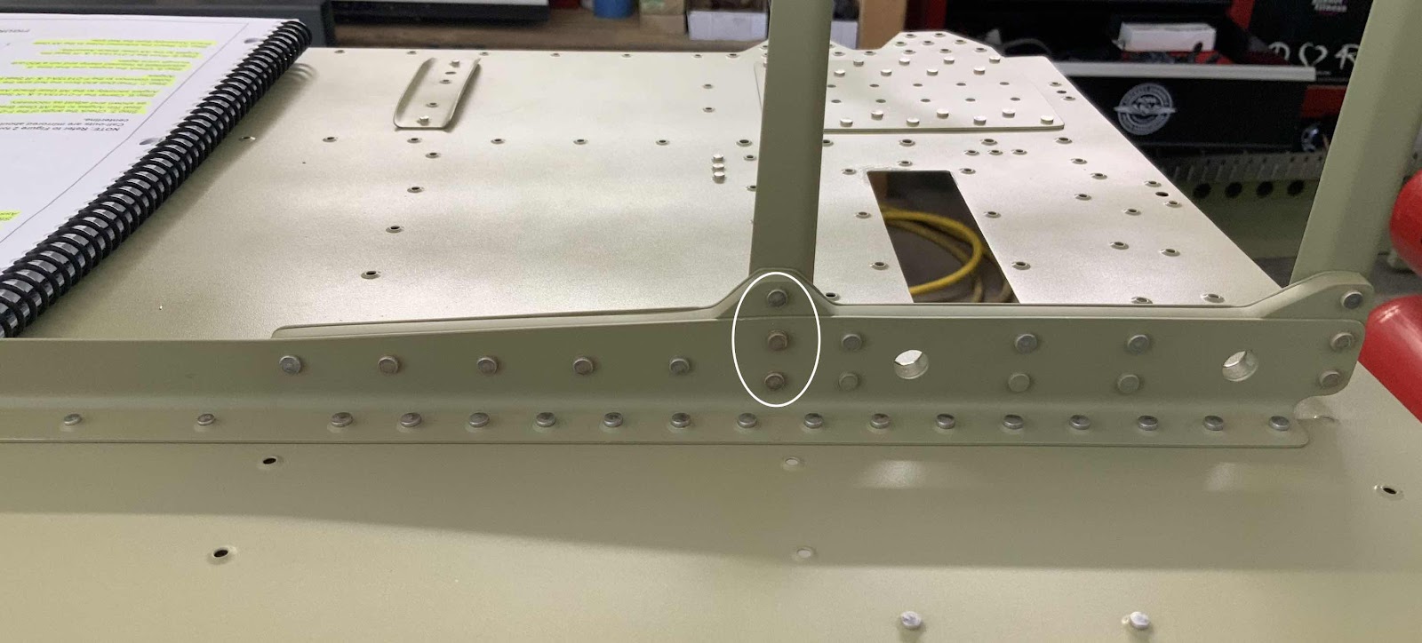
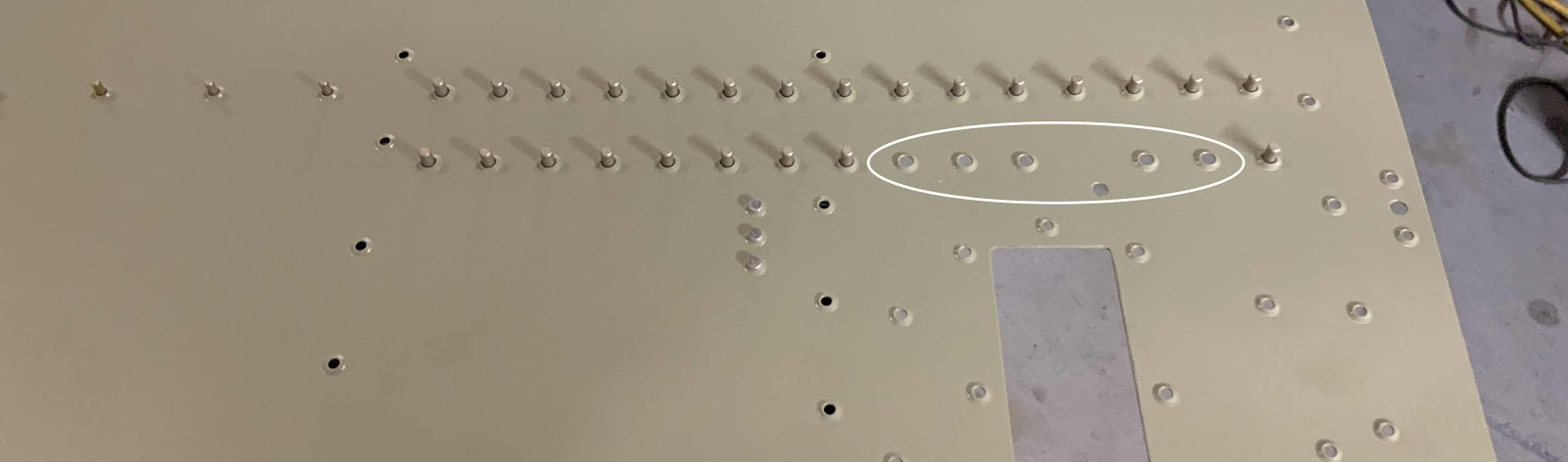
The Aft Gear Brace Assembly will be attached/riveted to the Center Bottom Skin as shown in the picture below. (The holes in the white circle will not be riveted at this time). I’ve inserted all the AN426AD4-4 into the appropriate holes and taped them in place. Here is a close up of what it looks like.
And here is an overview with both sides.
The Aft Gear Brace Assembly was put into place on the rivets shown above. I backriveted the Assembly to the Skin and the rivets turned out perfect. Here is the completed forward right side.....
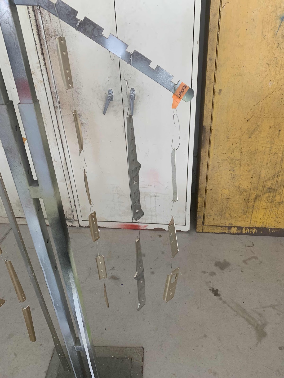
After being treated with Alumiprep and Alodine, all the parts prepared in the previous three Parts were sprayed with Akzo primer.
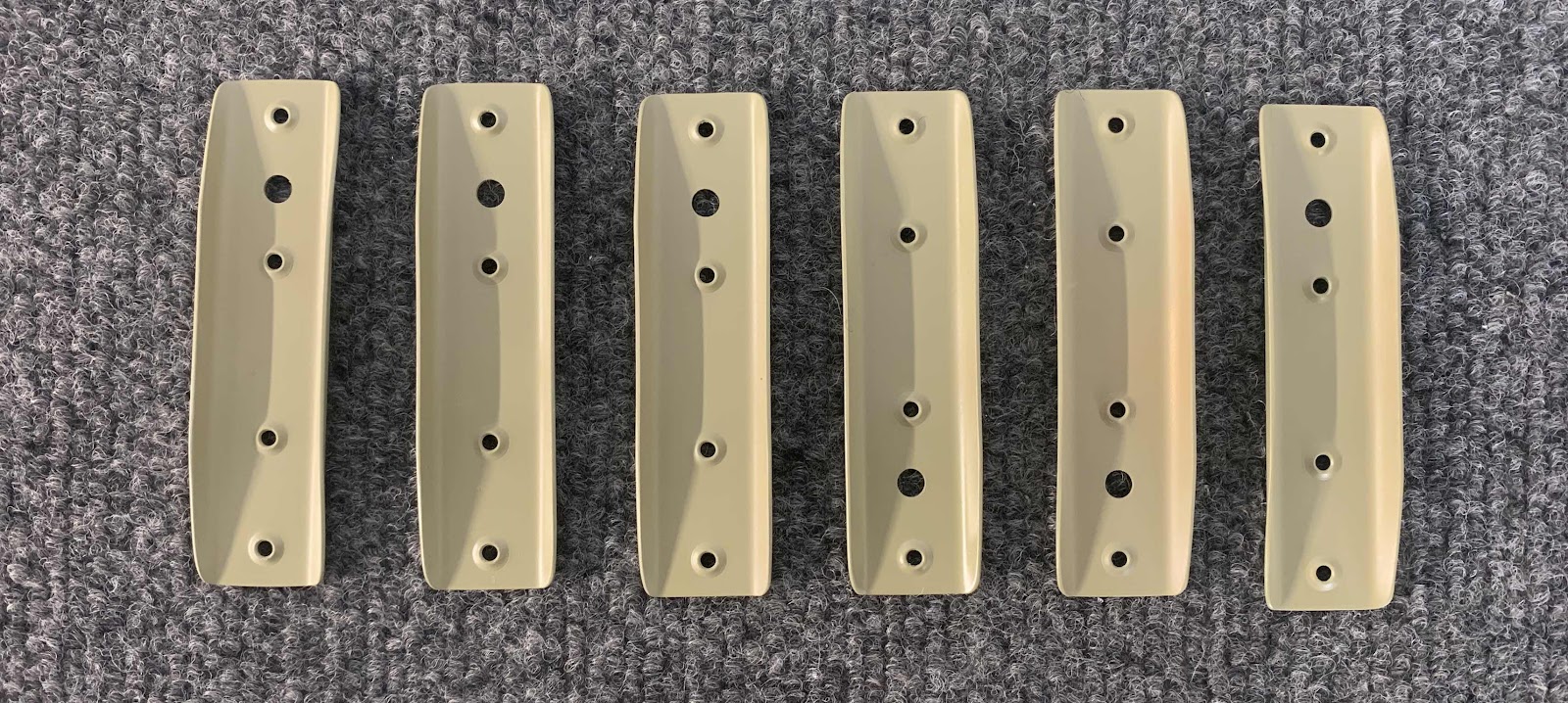
These are the six F-14140 Skin Stiffeners.....
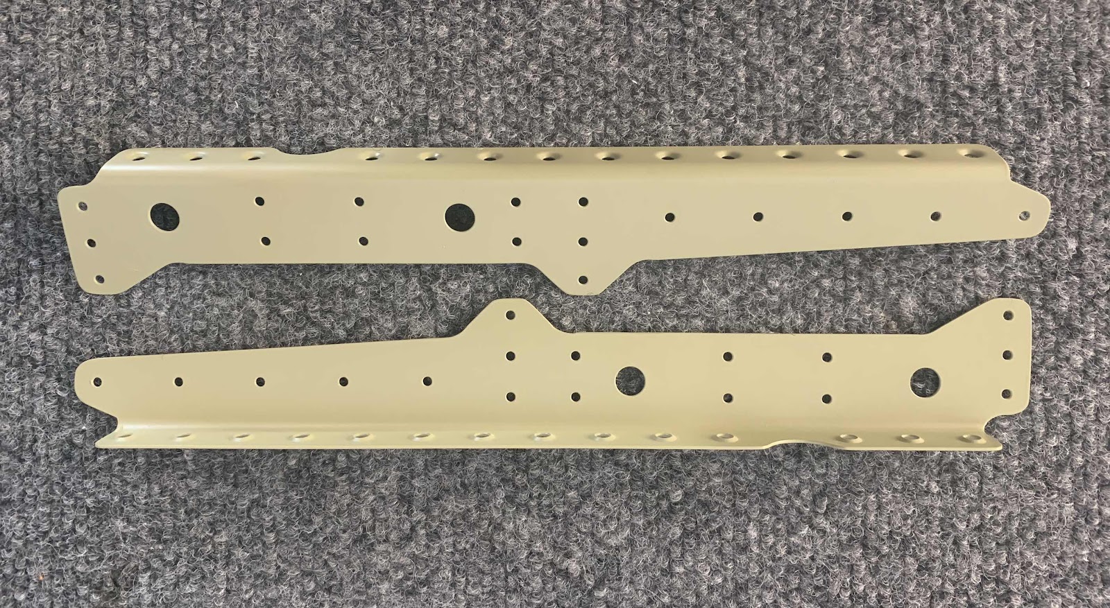
.....F-01443-L &-R Center Section Lower Doublers.....
.....F-14145 Step Attach Angles.....
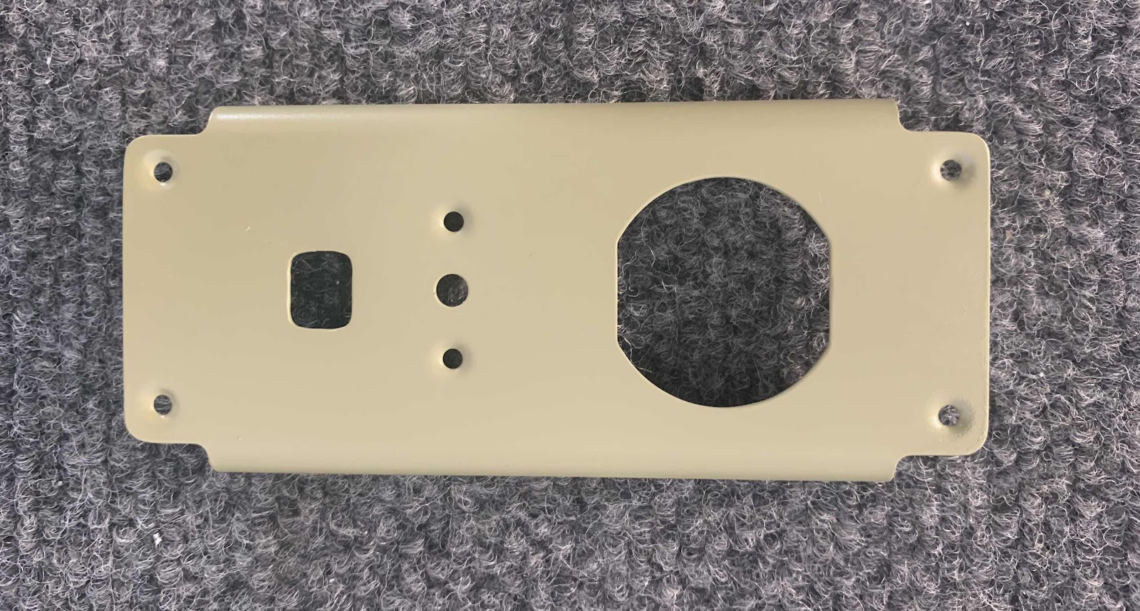
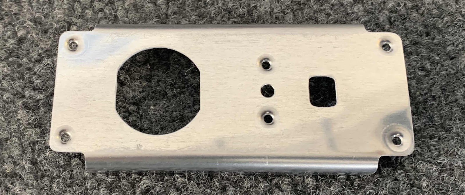
.....F-14123 Power Outlet Bracket.....
.....two F-01415A-L &-R and two F-01416B-L &-R Seat Rib Angles.....
.....F-01448B-L & - R Gear Brace Bars.....
.....F-01448C -L & -R Gear Brace Brackets.....
.....F-01448A Gear Brace Angle.....
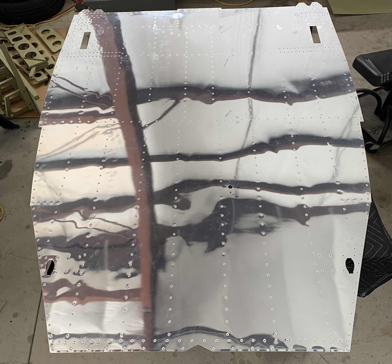
.....Bottom side (outside) of the F-01484 Center Bottom Skin.....
.....and the top (inside) of the Center Bottom Skin.
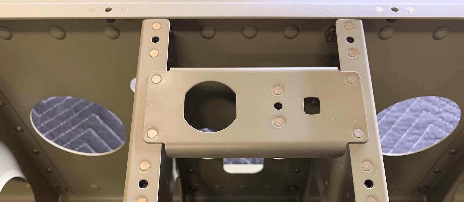
The Power Outlet Bracket received one single K1000-08D nutplate installed with two AN426AD3-3.5 rivets.
And then was installed between the two Inboard Seat Ribs as shown below with four AN425AD3-3.5 rivets.
Now, for the taildragger model, there are several locations that only get rivets installed in the hole with no parts attached to it. These locations are used to install parts for the tri-gear model, but are not needed for the taildragger. In the picture below, you can see four of those locations (they are the only holes with rivets in them).
Next, the six Skin Stiffeners were riveted to the Center Bottom Skin using AN426AD3-3.5 rivets. (The plans called for 3-3 rivets, but they measured a little short. The 3-3.5 rivets measured perfectly).
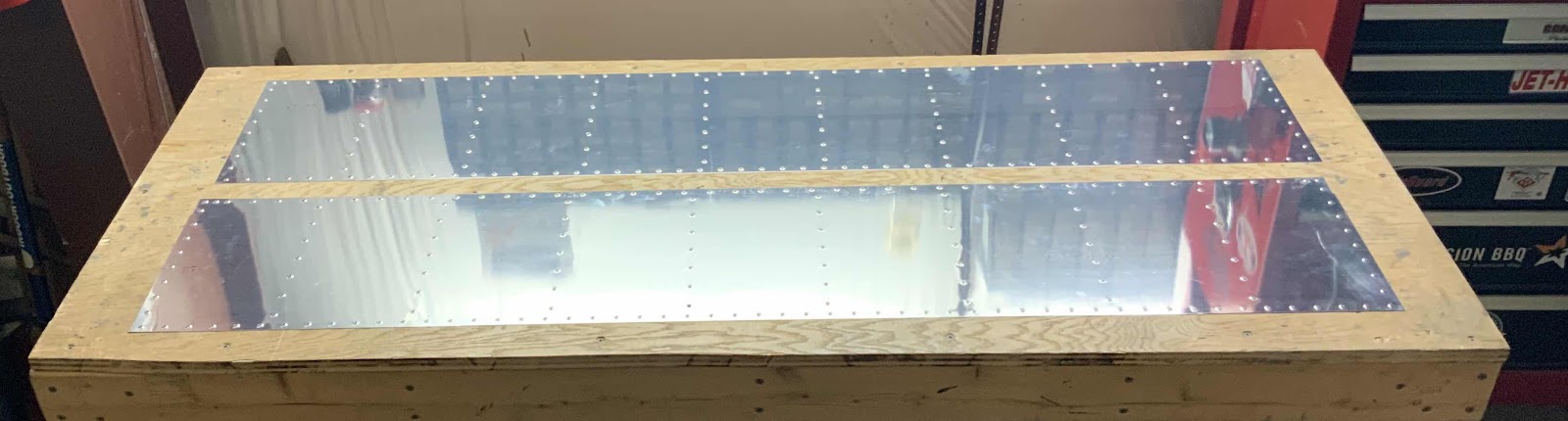
This is the bottom (outside) of the Center Bottom Skins showing the manufactured heads of the the AN426AD4-5 rivets attaching the Center Section Lower Doublers. This is the left side.....
.....and the right side.
This the right side showing the shop head side of the rivets and the associated Doubler.....
.....and the left side.
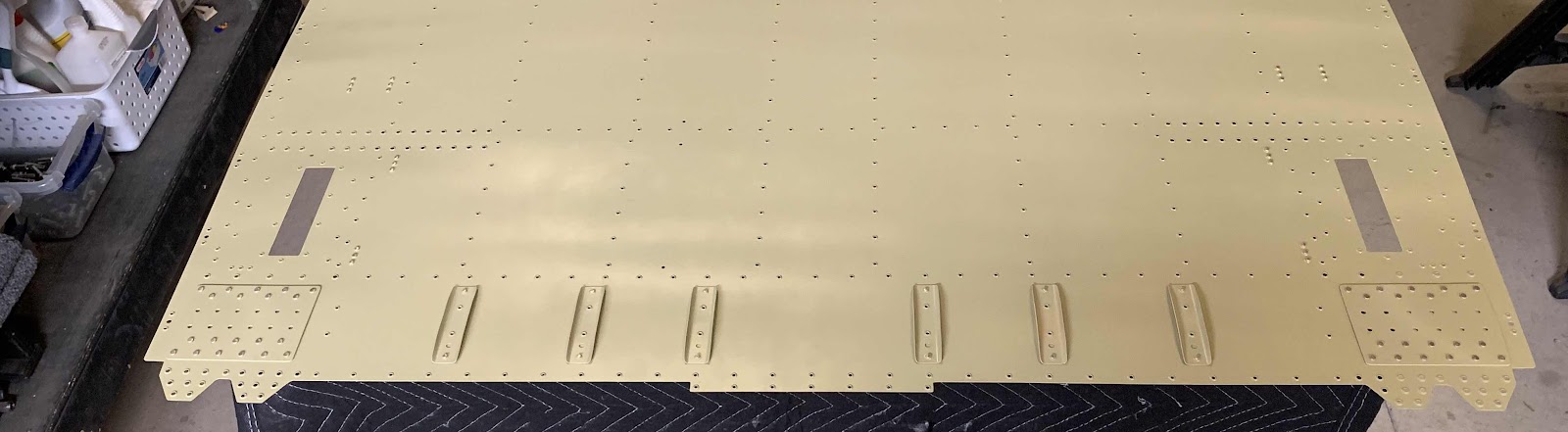
Here is an overall view of the Center Section Bottom Skin showing the six Skin Stiffeners and two Doublers.
To start this session, we started working on the F-14123 Power Outlet Bracket. The edges were cleaned, holes deburred and #40 holes dimpled.
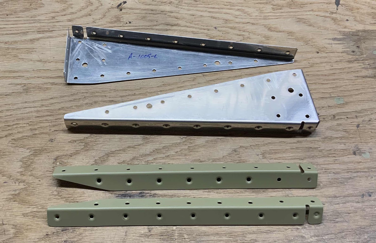
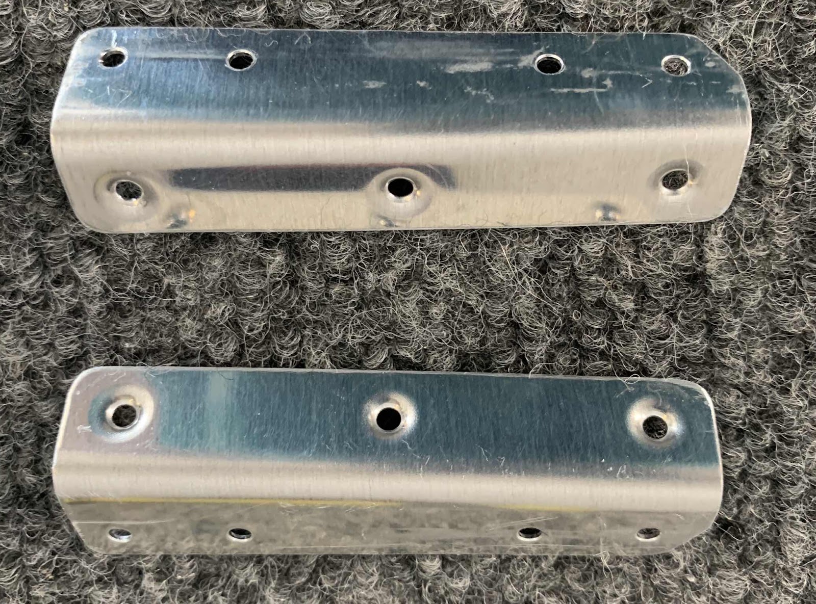
These are the F-14145 Step Attach Angles. The two angles were also prepared by cleaning the edges, deburring the holes, and dimpling the #40 holes. NOTE: these Angles are only necessary to install on the Tri-Gear.....UNLESS the Tailwheel builders wish to install the optional F-00018-L & -R Tail Dragger Steps. I will be installing the steps, so I prepared the Angles
Here is a view of the other side of the Angles.
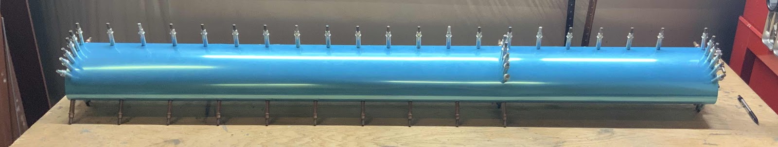
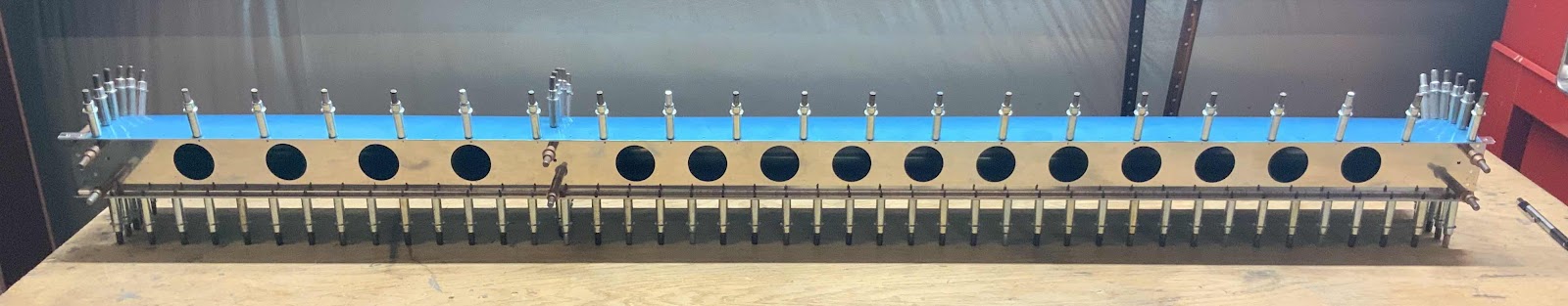
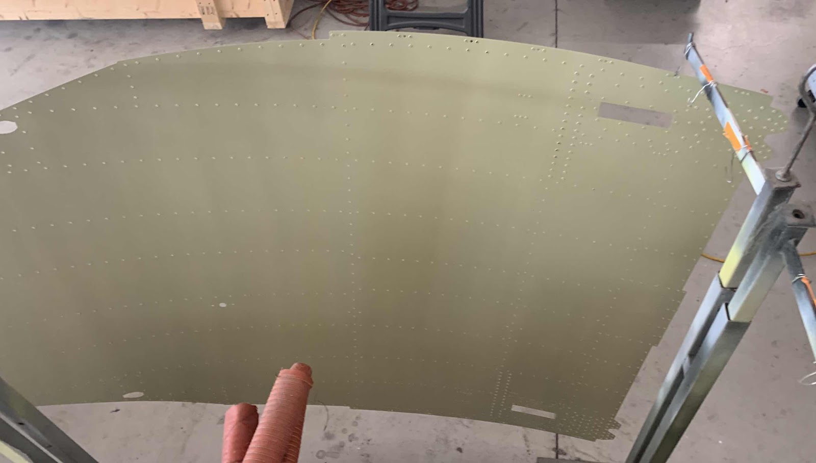
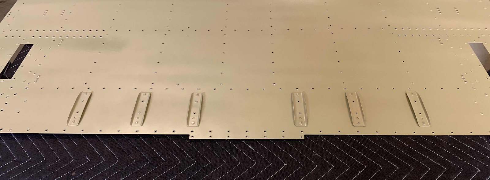
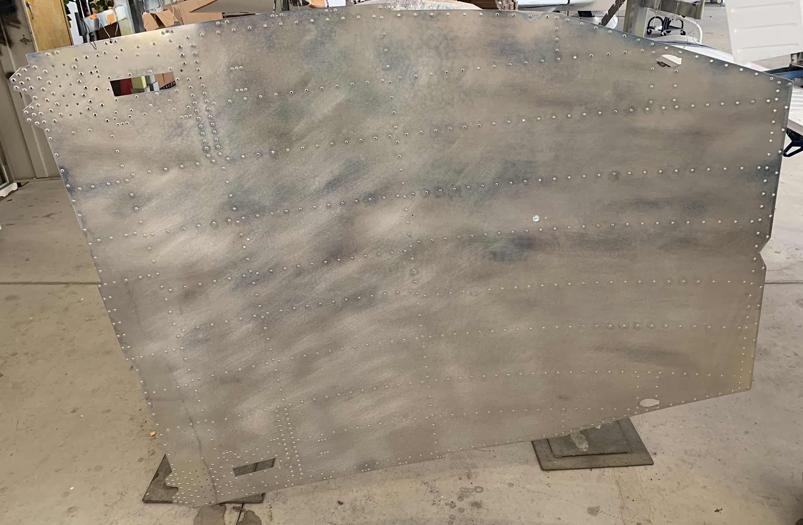
Below is the huge F-01484 Center Bottom Skin after being treated with Alumiprep and Alodine. It is now hanging up to dry.
The two pictures below show all the parts I prepared in Parts 16 and 17. They are also hanging up to dry following treatment with Alumiprep and Alodine.
In the previous session, I started dimpling the Center Bottom Skin. I used my pneumatic squeezer with a 3” yoke to dimple as many of the holes near the edges as possible. To start today’s session, I used the pneumatic squeezer to finish the holes around the edges and then the DRDT-2 to finish the remaining holes in the Bottom Skin. Here is the dimpled Center Bottom Skin.
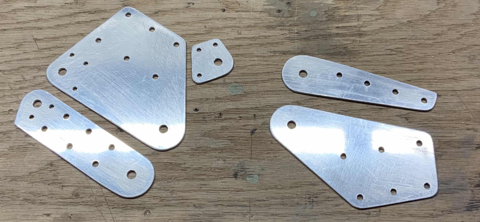
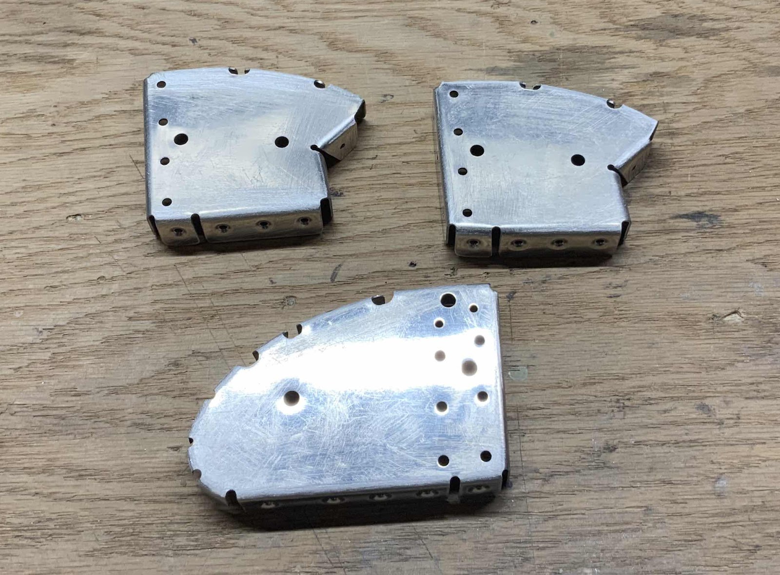
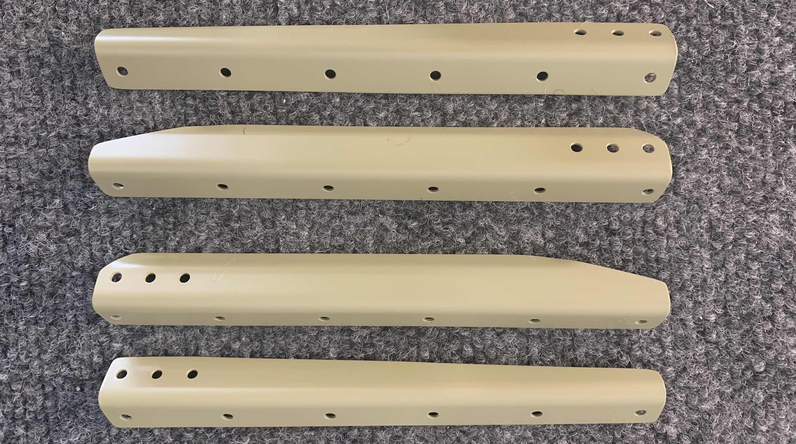
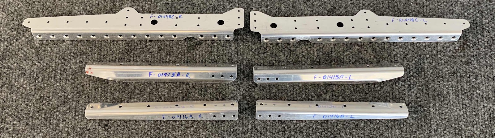
Pictured below is the F-01448C Gear Brace Brackets, F-01415A Seat Rib Angles, F-01416B Seat Rib Angles, and the F-01448B Gear Brace Bars. The first three parts were connected together in the center and had to be separated into -L & -R parts. Here’s the three parts after they are separated.....
.....and after the edges are cleaned, all the holes deburred, and the appropriate holes dimpled. These parts are now ready for Alumiprep, Alodine, and Akzo primer.
Kinda hard to see, but this is the F-01448A Aft Gear Brace. This part has had the edges cleaned, holes deburred, and the appropriate holes dimpled. This part is also ready for Alumiprep, Alodine, and Akzo primer.