This blog was created to memorialize the building process of my Van's Aircraft RV-14 and to satisfy the requirements for certification in the Experimental Amateur Built Aircraft category. It will also serve as a central location for ME to reference in the future on processes and techniques I used during the build. Additionally, it will allow my family, friends, and other interested builders the opportunity to follow along during my build…..and might be helpful to someone along the way.
My buddy Jeff had a few minutes to help me out tonight, so we were able to finish riveting the remaining Wing Ribs. We riveted Wing Ribs #4 - #11 to the Right Wing Main Spar using AN470AD4-7 universal rivets. We used a 3X rivet gun and tungsten bucking bar to complete the rivet installation.
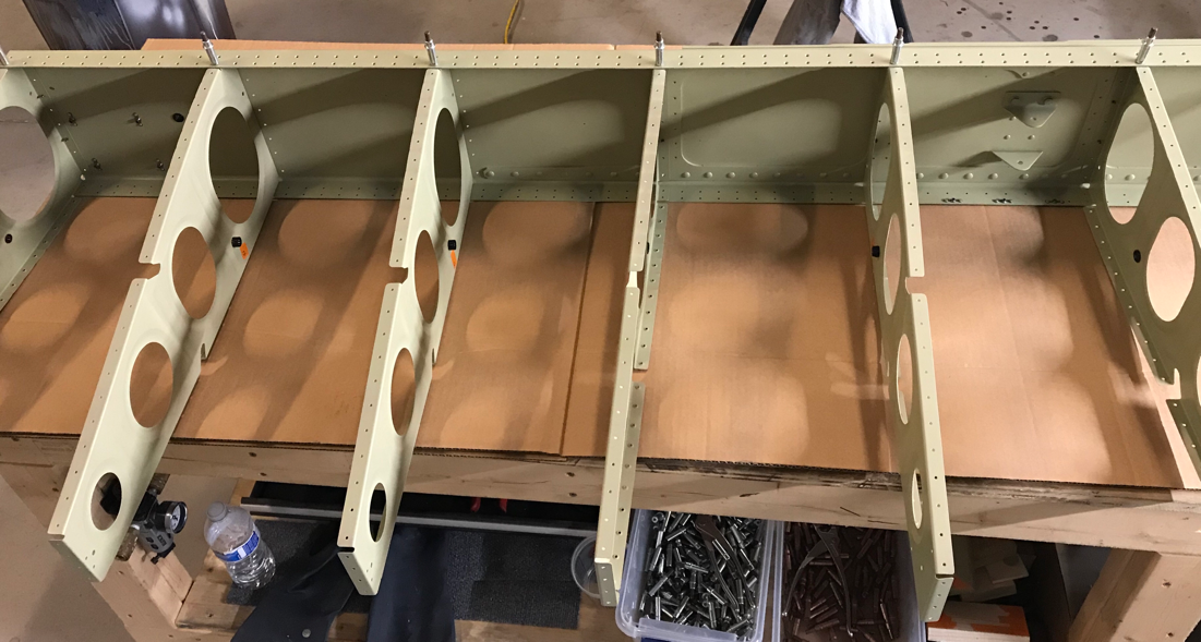
This is the forward side of the Right Main Spar looking from inboard to outboard. You can see the vertical rows of shop heads of the installed rivets.
The is the opposite end of the Right Main Spar looking outboard to inboard. You can also see the vertical rows of shop heads.
Finally, this is a small section of the Right Main Spar between Wing Ribs #9 and #10. From this view, you can see the 10 manufactured heads of the installed rivets (5 on each Wing Rib).
After riveting all the Wing Ribs (except #14, as directed by the plans), I finished the prep work on the Right Rear Spar. I deburred the holes previously drilled for the Spar Doublers and cleaned all the edges. The next step is to dimple the upper and lower Flanges of the Right Rear Spar. Then, the Rear Spar and associated parts can be Alodined and Akzo primed.
Now that the Wing Ribs are clecoed back into place on the Right Main Spar, it was time to install the bolts/washers/nuts and rivets. Below is the excerpt from the plans regarding the installation of the bolts. NOTE: the picture below is for the LEFT WING. The Right Wing bolts/washers/nuts are installed in the same way and orientation. For my own tracking purposes, I highlight the bolts as they were installed to insure the proper size/length and orientation. My buddy Doc helped me install and torque all the bolts. These bolts, just like on the Left Wing are torqued to 42 inch pounds (14 in lbs friction torque plus 28 in lbs for the self locking nut).
Now on to installing the rivets.....Since I was working working alone, it was the easiest to get the Ribs on the ends. I was able to install the AN470AD4-7 universal rivets on Ribs #1, #2, and #3. I also installed the bolts/washers/nuts as I progressed from #3 to #1 (not previously installed to make room for rivet installation on the adjacent Ribs). I’ll get to Ribs #4 - #11 when I can get my buddy’s assistance. I definitely install them myself (I did them by myself on the Left Wing), but I think it will be much easier and go faster with two people.
I’ve continued working on the Right Wing each night since my last post on the 21st. However, I didn’t get around to posting anything. I figured I would wait until each of these steps were completed and submit one post encompassing all the work.
January 22, 2018
Each of the 14 Right Wing Ribs needed some minor work on the System Holes. For example, in the picture below, the two circled holes needed to be enlarged with a unibit to 1/2”. Additionally, one of the two holes on the left was not pre-punched from Van’s. The second hole had to be marked/drilled using measurements provided in the plans (6 3/8” from the end and 4 1/4” from the small pre-punched hole).
Since all 28 System Holes in the Right Wing receive SB500-6 Snap Bushings, all 28 holes were enlarged to 1/2” with a unibit. Wing Ribs 1 - 8 has the Systems Holes oriented as shown in the picture below......
.....and Wing Ribs 9 - 14 are oriented as shown below.
Drilling the Systems Holes was difficult, just took a little time. Once all the holes were enlarged, I used 220 grit sandpaper to make sure all/any burrs were removed.
January 23, 2018
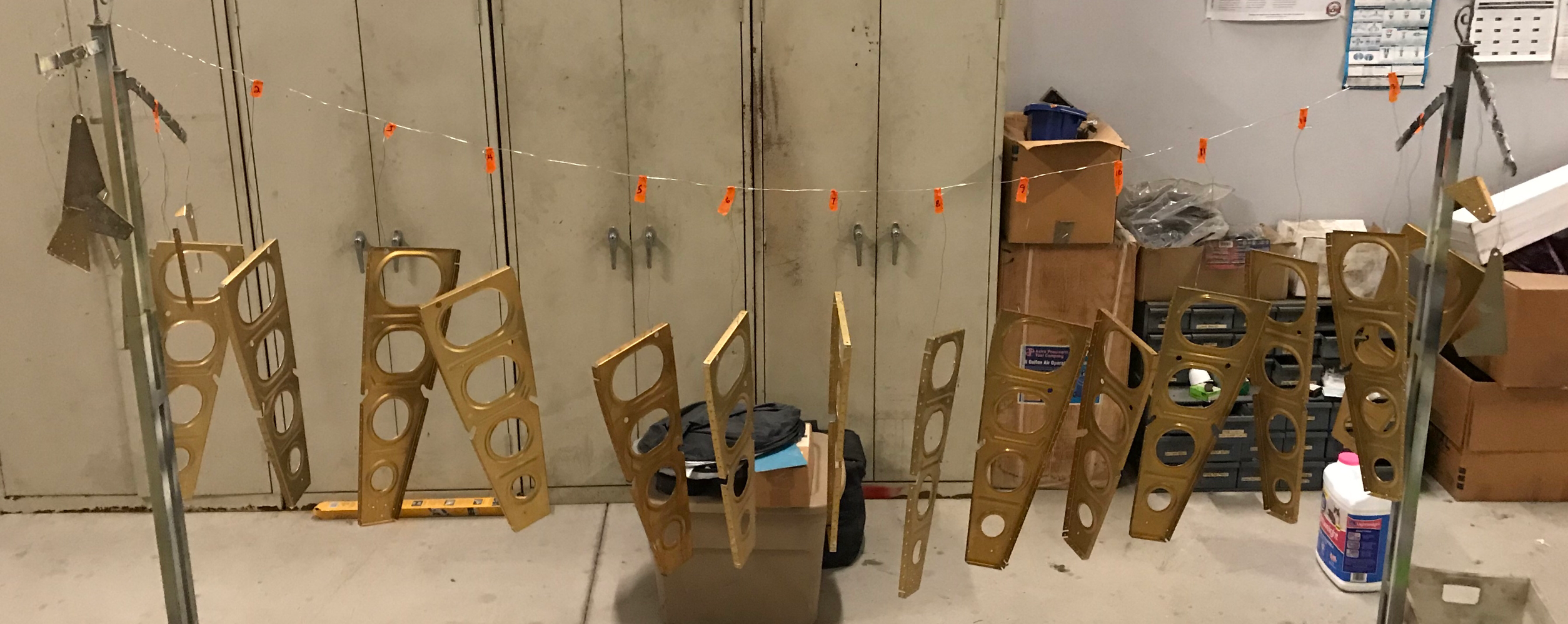
Just like with the Ribs on the Left Wing, I have bins large enough to dip/submerge the Ribs in the appropriate chemical. Initially, each piece is submerged in Alumiprep 33 and then Alodine 1201. After the Alodine, the parts are hung up to dry on my “clothes line”. The orange tabs above each Rib is the numbering system I use to keep each Rib where it is supposed to be and re-installed correctly on the Main Spar after being fitted. Shown below are the 14 Wing Ribs, the parts that make up the Flap Hinge Brackets, and the parts that make up the Torque Tube Support Bracket Assembly.
Today, January 24, 2018
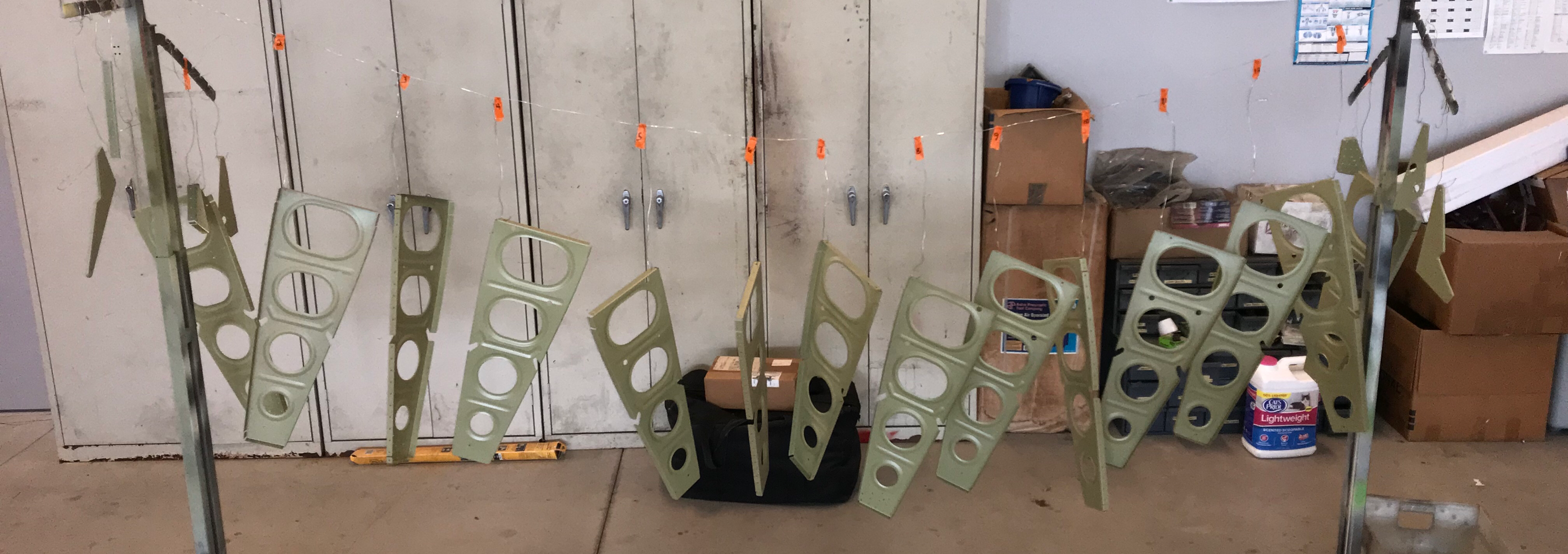
I started today’s session by Akzo priming all the parts that were Alodined yesterday. Below are the parts hanging up to dry on my clothes line.
After letting the parts dry for a couple of hours, I started the initial riveting process. The first parts to get riveted were the Wing Rib #3 and #8, the Flap Hinge Bracket, and the Flap Hinge Rib. There were 16 AN470AD4-7 universal rivets installed on each Rib. The picture below shows each of the Ribs.....one showing the manufactured heads and the other showing the shop heads.
The next parts to be riveted together made up the Torque Tube Support Bracket Assembly. AN470AD4-5 and 4-6 universal rivets were used to complete the assembly.
Finally, per the plans, 12 of the 14 Wing Ribs were re-clecoed to the Righ Main Spar. As I found out on the Left Wing, Wing Ribs 1 and 2 are temporarily left off to aid in the rivet installation of Rib #3, and then Rib #2.
During the next session, I will begin riveting the Wing Ribs to the Right Main Spar.
After I primed the Right Main Spar in Section 13, I was storing it in the same plastic and shipping crate from Van’s. I figured it would be the best way to protect it while it was waiting on its turn on the assembly line.
As I mentioned in my previous post, I’m having to backtrack to Section 14 to complete the initial steps on the Right Wing. The first thing is to cleco the Torque Tube Support Assembly to the Upper and Lower Flanges of the W-1010 Inboard Wing Rib and final-drill #30 the W-1029C Angle to the Wing Rib.. This step went REALLY, REALLY fast, as I already accomplished this while working on the Left Wing.
The W-1025A Flap Hinge Brackets needed to be straightened to remove any bowing from the manufacturing process. This step also went REALLY, REALLY fast....it was also completed with the Left Wing.
The Flap Hinge Ribs, Flap Hinge Brackets, and Inboard Wing Ribs (W-1011-L & -R) were clecoed together and match-drilled to #30 using the Flap Hinge Ribs and Flap Hinge Brackets as drill guides.
The outermost Wing Rib (#14–if you recall my numbering system from the Left Wing) had to have a portion of the Flange material removed (just like the Left Wing). Here is the excerpt describing the area to be removed. I removed this area the same way as before.....I used a small cutting wheel on the Dremel Tool to remove the majority of the material. Once that was complete, I used a small fine hand file and 220 grit sandpaper for the final shape.
The 22 bolts, washers and nuts were removed from the Right Main Spar Assembly and will be set aside for Wing Rib installation in a later step.
All the Inboard and Outboard Wing Rings were clecoed into place on the Right Main Spar. I also clecoed the Right Rear Spar to the assembly to give the Wing Ribs some stability and hold everything somewhat together. This is the Right Wing with all the Wing Ribs clecoed into place. All the common #30 attach holes in the forward Flanges of the Wing Rib and web of the Main Spar were final-drilled. Additionally, all the common #40 attach holes in the Upper and Lower Rib Tabs and Flanges of the Main Spar were also final-drilled.
Now, guess what comes next.....mark the Rib locations on the Main Spar.....remove and deburr freshly drilled holes. Done!
Below is the torque value chart from section 5.20 of the builders manual. The bolts used for the Wing Rib to Main Spar installation are all AN3 and use MS21042-3 Self Locking Nuts. As described below, you first need to determine the friction drag torque for the bolt/nut combination. Van’s tests showed an average friction drag torque of 14 in-lbs, but indicated results may vary. I also had a 14 in-lbs friction drag torque value, so I will use the same as Van’s. So, for the correct torque value, you take the friction drag torque value (14 in-lbs), the value shown in the chart (28 in-lbs), and add them together for a total torque value of 42 in-lbs. This bolt/nut combination will get torqued to 42 in-lbs. In Post #17, you can see an excerpt of where the bolts go and what orientation.
Wing Ribs #14, #13, and #12 do not utilize bolts (only rivets), so they are excluded for the time being. The plans state to cleco the W-1012-L & -R Outboard Wing Ribs and all W-1011-L & -R Inboard Wing Ribs (except the inboard most W-1011-R) to the Main Spar Assembly.....as shown in Step 1 below.
There is a note to NOT install the nuts and washers on the three most Inboard Wing Ribs (#1, #2, and #3) at this time. Additionally, in the second part of Step 3, it says “for the three most Inboard Wing Ribs, it will be necessary to push the bolt out of the way to set the rivets”. What rivets? It never specifically says in the plans, but it’s the small AN426AD3-3.5 rivets installed in the forward most hole in the forward tabs of the seven W-1011-L & -R Inboard Wing Ribs (Ribs #2 through #8).
The excerpt from above also shows the locations and size of rivets to install for the Wing Ribs and Main Spar. Most of today’s session was devoted to installing these rivets and I used the weapons below.....
Because of how the Wing Ribs are made , you are not able to get a straight shot on the manufactured head of the rivet. So, that is the reason I used the Offset Cup Set. I really don’t like using this rivet because it takes a few more hits to set the rivet.....because it’s offset. I personally also find it difficult to ensure the Set is square to the rivet head. I have to admit, I have a few “smiles”. I normally use my Sioux 2X rivet gun, but because all the rivets used are #4, I used my buddies 3X gun. The tungsten bucking bars are awesome! Get yourself one....or two.....you won’t regret the purchase.
There are 72 rivets that attach Wing Ribs #1 through #13 to the Main Spar Assembly. (Wing Rib #14 is only clecoed at this point and will be riveted later along with one of the Leading Edge Ribs). The vertical rows of rivets are the shop head for Wing Ribs #13, #12, and #11.
Here is where I deviated from the plans just slightly to complete Wing Ribs #1 through #4. Because they are so close together (wing walk area), it is difficult to get the rivet gun in between them. So, I removed Ribs #1 through #3 and riveted Rib #4. Then, clecoed Rib #3 and riveted, then #2, and then #1. This gave me plenty of room for the rivet gun and kept the Ribs out of the way.
Additionally, I previously did not rivet the Torque Tube Support Bracket Assembly to the most Inboard Wing Rib. If you follow this step in the plans and rivet the Assembly to the Wing Rib, you will not be able to get your rivet gun on the manufactured heads of the rivets from the Rib to Spar. So, I riveted Rib #1 to the Main Spar FIRST and then riveted the Assembly to the Rib.
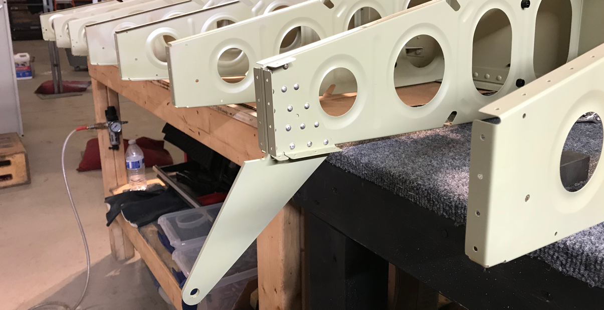
The picture below shows the #1 Wing Rib riveted to the Main Spar and the Torque Tube Assembly riveted to the Wing Rib. You may notice that one of the rivets from the Assembly to the Rib #1 doesn’t look like the others. Ideally, you want the manufactured head of the rivet on the thinnest of the two pieces of aluminum. Again, because Ribs #1 through #4 are close together, you can’t get a rivet gun in there.
I used my pneumatic squeezer to set the very top and three middle rivets (pictured above and below), my had squeezer to set the very bottom rivet (pictured below.....assembly was flipped upside down), and the rivet gun/bucking bar to set the rivet in the opposite direction. Because of the Flange Bearing, I couldn’t get either squeezer on that rivet and had no choice but to set it the opposite way.
Anyway, Section 14 is now complete. Section 15 will be the Rear Spar and I will start there next time.
I started tonight by riveting the Inboard and Outboard Flap Hinge Assembly’s together. Each assembly is made up of an Inboard Wing Rib, Flap Hinge Bracket, and Flap Hinge Rib.
AN470AD4-7 universal rivets were used on each assembly (16 rivets per side) as shown in the two pictures below. After the Ribs were clecoed to the Main Spar, it was held reasonably steady. So, I used the rivet gun and bucking bar to set all 32 rivets. I was able to do it solo, but did make a few “smiles”.....a result of me trying to go to fast.
Not anything to really show, but I also started installing the bolts/washers/nuts attaching the Wing Ribs to the Main Spar. In order to keep everything clear in my mind, I have numbered each of the Wing Ribs from 1 - 14 (inboard to outboard). Seems like a simple thing to do, but it has definitely helped me keep the Ribs easily identifiable and in the right place. You can see in the plans excerpt below, I have also numbered the Ribs in pencil on the drawing. As far as installing the bolts, the plans look a little busy and were a little hard to follow at first glance. However, just like anything else I guess, once you get it, you get it. The last three Ribs (#12, #13, and #14) do not have any bolts and will only use rivets for their installation.
The instructions were very clear that the bolts MUST be installed oriented exacelty as shown below. So, I paid particular close attention while installing them. I will torque them appropriately tomorrow according to the values in the table from Section 5.20.
Only a few steps left to finish Section 14. Hopefully, I’ll be able to complete this section tomorrow.
Not much progress today, but progress nonetheless! I clecoed all the Wing Ribs to the Left Main Spar, except numbers #3, #8, and #1. For Ribs #3 (W-1011-R) and #8 (W-1011-L), I need to complete the riveting of the Flap Hinge Bracket and Flap Hinge Rib to the Rib. The plans have you hold off on installing Rib #1 (W-1010-R) for the time being. So, at the moment, 11 Wing Ribs are clecoed to the Left Main Spar.
According to the plans, the next step is to rivet and bolt the Wing Ribs to the Main Spar.
As described in yesterday’s post, 23 parts/pieces were Akzo primed and allowed to dry overnight. I started tonight by numbering each of the Wing Ribs as I took them off the “clothesline” (you can see Ribs #1 and #2 marked below). I also installed the 29 plastic Snap Bushings.
Next, I assembled and riveted the Torque Tube Support Bracket Assembly together. Here are the five pieces that make up the assembly.
Here is the assembly after being riveted together. This is the manufactured head side.....
I Akzo primed all 14 Left Wing Ribs, the five pieces of the Torque Tube Support Subassembly, two Flap Hinge Brackets, and the two Flap Hinge Ribs. I will let them all completely dry overnight and start riveting pieces together tomorrow.
Today, I will concentrate on corrosion protection for the Wing Ribs. To started, I completed the last little bit of fluting, but all of the remaining metal work has been completed. The last step is to treat the Ribs with Alumiprep 33, Alodine 1201, and Akzo Epoxy Primer. The easiest way, I have found, is to dip the parts in the chemicals (verses scrubbing with Scotoch-Brite for the Alumiprep and brushing on the Alodine with a foam brush). I did have to get three larger containers due to the length of the Ribs. Below, I have the three bins set up with the appropriate chemicals and rinse.
Alodine 1201 Distilled Water Alumiprep 33
In the bins above, you can see Rib #1 already in the Alumiprep.....let those little guys eat!!!!! Anyhow, my process is:
Alumiprep.....4 minutes (flip halfway through)
Rinse
Alodine.....3 minutes (flip halfway through)
Rinse
Hang up to dry
Now that the process is set up and ready, here is the pile of parts that need to be corrosion treated.
As previously stated in the build plans, it is important for the Wing Ribs to be re-installed on the Main Spar as they were during the final and match-drilling process. Because of this, I previously numbered the Ribs from 1 to 14 (inboard to outboard). I set up the drying rack numbered the same way marked with the orange tape.....Rib 1 on the left (already hanging up) and Rib 14 on the right.
Here are all the Wing Ribs and associates parts after being corrosion treated. The only step left is to prime them with the Akzo Epoxy Primer (tomorrow).
I’ve put in a couple of small work sessions over the past few days, but didn’t enter anything on the site. I will catch everything up on this post.
In Part 11, all the Ribs were clecoed to the Left Main Spar and the appropriate holes were final-drilled or match-drilled #12, #30, or #40 according to the plans. All those holes were then deburred. After that was complete, I marked all 14 Ribs to make sure they are installed in the same location later in the final assembly.
Also during Part 11, the Flap Hinge Brackets, Flap Hinge Ribs, and Inboard Wing Ribs were match drilled #30. All of these holes were deburred and the edges of the thick Flap Hinge Brackets were cleaned an prepared.
That catches up on the couple of small sessions and the site is now up to date.
So, moving on to today’s work. In the excerpt below, you can see all the Snap Bushings that need to be installed in the Wing Ribs.....29 in total.
There are three sizes of Snap Bushings installed in the Left Wing during this portion of the build:
SB375-4.....holes step drilled to 3/8
SB500-6.....holes step drilled to 1/2
SB437-4.....holes step drilled to 7/16
Eight of the Ribs had to have an additional hole drilled in the web of the Rib according to the except below. The Upper Aft Systems Hole needed to be drilled according to the measurements shown below. Additionally, the Ground Lug Hole had to be enlarged to #19 on the W-1010-R Inboard Wing Rib.
This brings me to a point to start final assembling parts and pieces. However, prior to doing that, I need to treat everything with Alumiprep, Alodine, and Akzo Epoxy Primer. I will start that process tomorrow.
I started today’s session by making sure the four W-1025A Flap Hinge Brackets were straight and flat. They come in a package of four and all four needed slight adjustments. Section 5.13.1 of the plans discusses how to straighten thick aluminum parts.....I followed the WHANG method!
Here is one of the Flap Hinge Brackets.
The W-1025B-R / W-1025B-L Flap Hinge Ribs and W-1025A Flap Hinge Brackets were clecoed to the W-1011-L / W-1011-R Inboard Wing Ribs. Now, the 14 common #30 holes are match-drilled and the two alignment holes are final-drilled #30. (The two below are for the Left Wing and the process will be repeated for the Right Wing).
The aft Flange (but not the radius of the Flange) had to be removed from one of the W-1012-R Outboard Wing Ribs as shown in the excerpt below.
I used my Dremel tool to cut off the Flange just below the holes and used a fine file and 220 grit sandpaper to make the final a shape. Here is the result.
Next is to remove all the bolts, nuts, and washers from the Left Main Spar Assembly and set them aside for later use. There were 11 bolts on the Upper Flange (top row) and 11 bolts in the Lower Flange (bottom row).
After removing all the bolts, the W-1010-R Inboard Wing Rib, W-1011-L & -R Inboard Wing Ribs, and W-1012-L & -R Outboard Wing Ribs were clecoed to the Left Main Spar Assembly. The picture below shows all 14 Ribs clecoed to the Left Main Spar. According to the plans, a whole lot of drilling is about to happen.
#12: Upper and Lower holes of the Rib Flanges that will use bolts/nuts to attach to the Main Spar Assembly
#30: All remaining common attach holes in the Forward Flange of the Ribs and Web of the Main Spar Assembly
#40: All common attach holes in the Upper and Lower Rib Tabs and Flanges of the Main Spar Assembly
****Then, of course, everything will be disassembled and you have to debur all the freshly drilled holes****