This blog was created to memorialize the building process of my Van's Aircraft RV-14 and to satisfy the requirements for certification in the Experimental Amateur Built Aircraft category. It will also serve as a central location for ME to reference in the future on processes and techniques I used during the build. Additionally, it will allow my family, friends, and other interested builders the opportunity to follow along during my build…..and might be helpful to someone along the way.
Showing posts with label Section 29-FWD/MID Side Structure. Show all posts
Thursday, August 6, 2020
Wednesday, June 3, 2020
Saturday, April 25, 2020
Fuselage, FWD/MID Side Structure (Part 41)
I previously delayed the next few steps from when I was working on Section 29 in early January (reason for the gap in this and the previous Part) for a couple reasons. One: I ordered, and was waiting on, the black aluminum vents from Van’s to replace the plastic ones from the kit. Two: There is a note in the plans that says, “Delay the following steps until after the completion of Section 35 to eliminate the possibility of interference with the bottom of the instrument panel”.
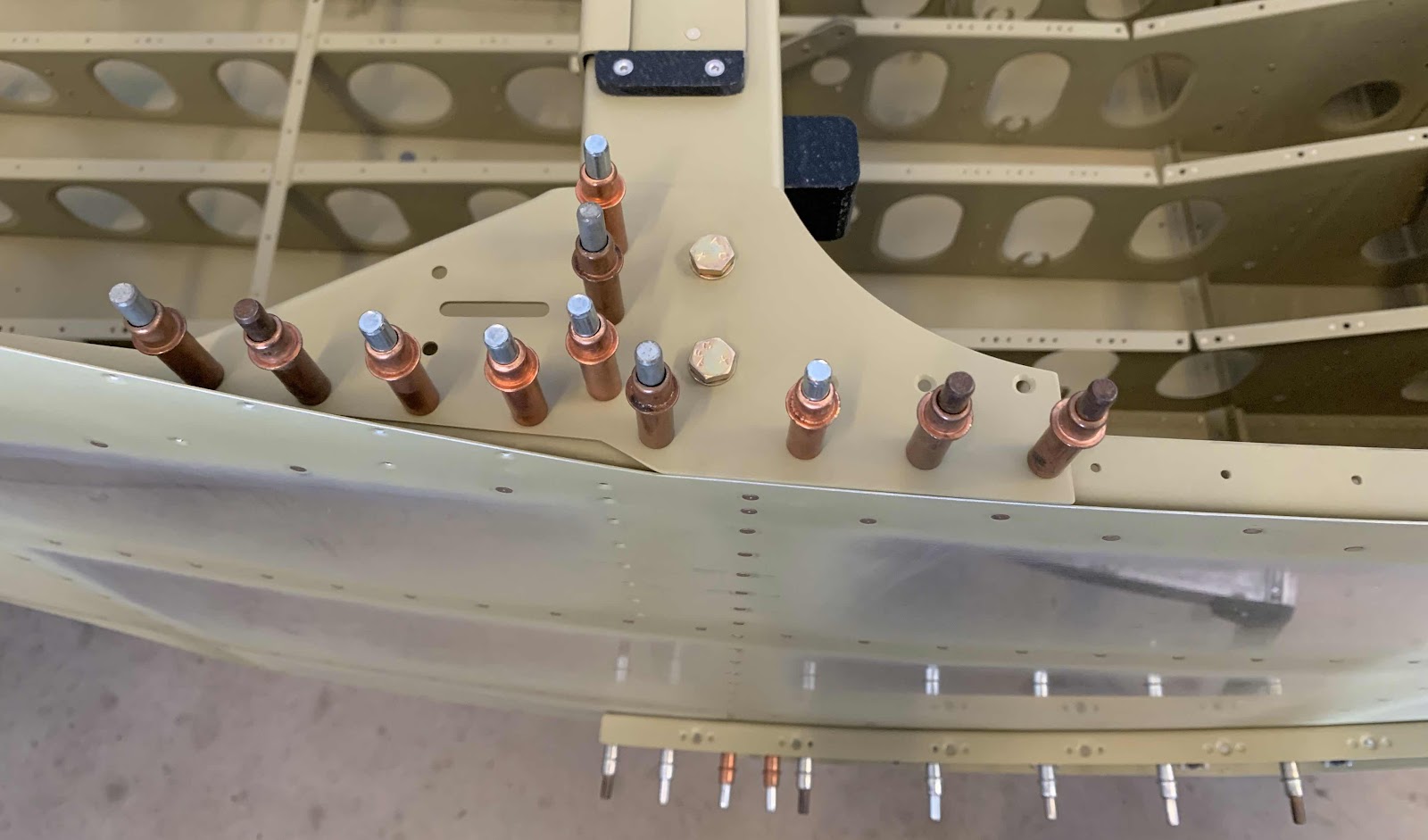
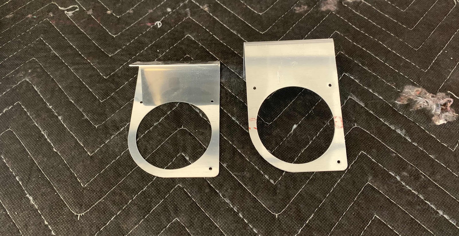
So, now that the instrument panel was installed, I came back to this Section to complete these few steps. First, I separated the F-14186-L & -R NACA Vent Brackets. Here are the Brackets after I separated them, deburred the holes and cleaned the edges. They are now awaiting treatment with Alumiprep, Alodine and Akzo primer.
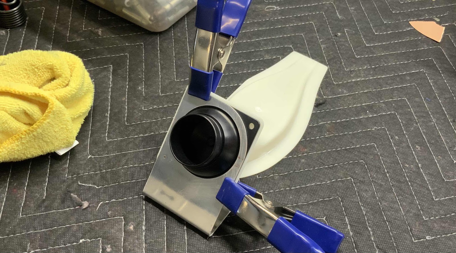
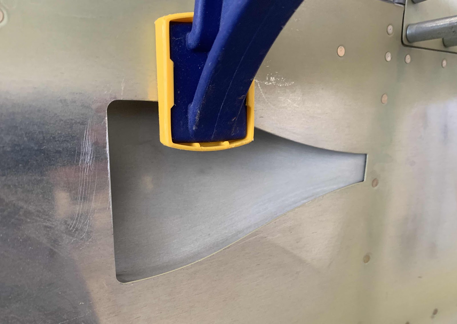
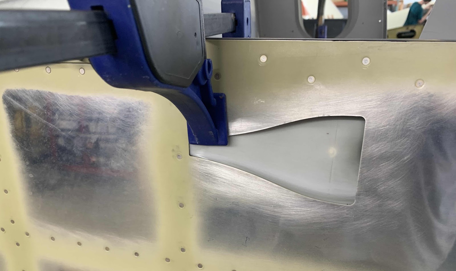
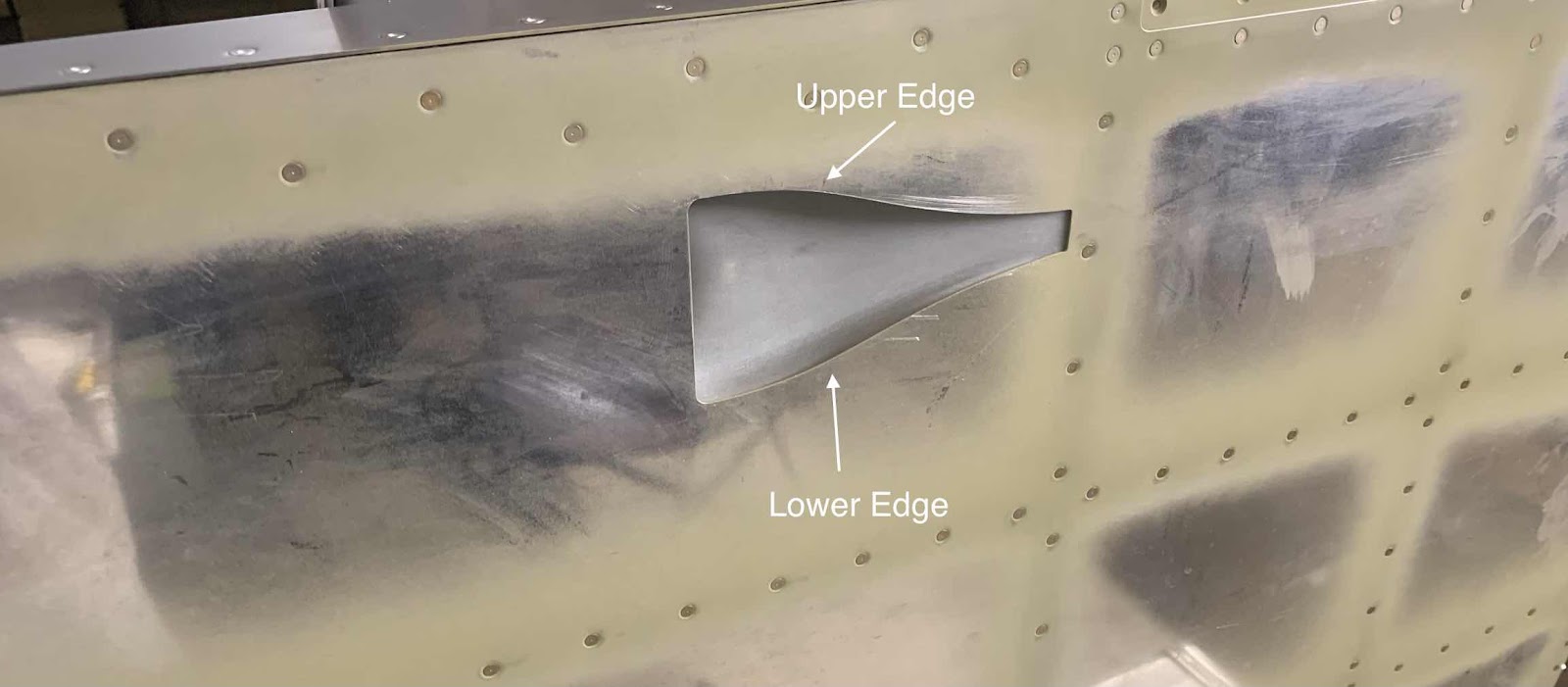
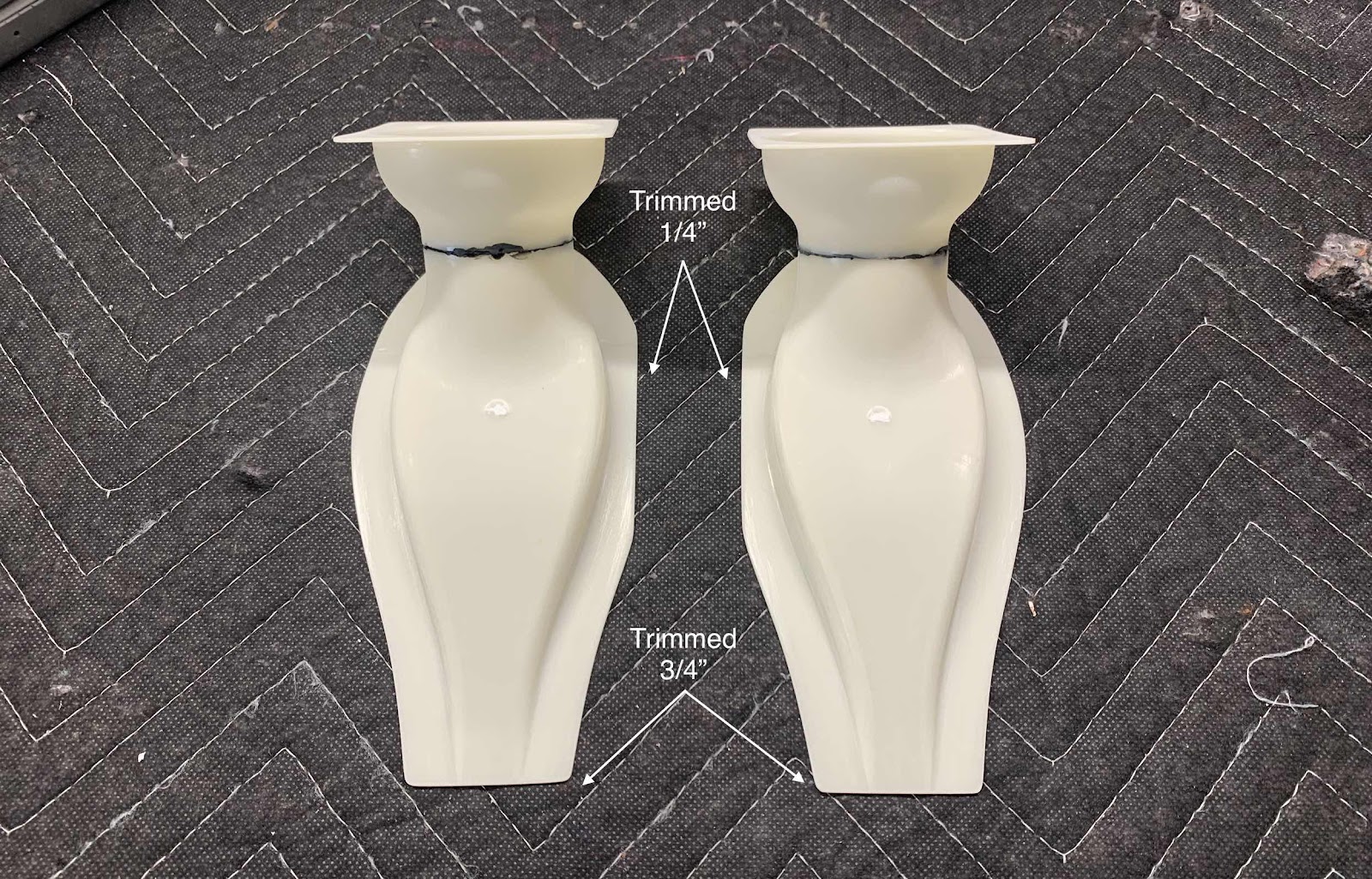
The note didn’t necessarily apply to separating the NACA Vent Brackets, but will definitely apply to the VENT SV-10 Fresh Air Vents. First, the Fresh Air Vents had to be trimmed as indicated in the picture below. I measured the correct trim lines and marked them with a Sharpie. I used a belt sander to remove a majority of the material and 320 grit sand paper for the final trim
I’m sure this wasn’t completely necessary, but I clamped the two Fresh Air Vents together to make sure they were the same.
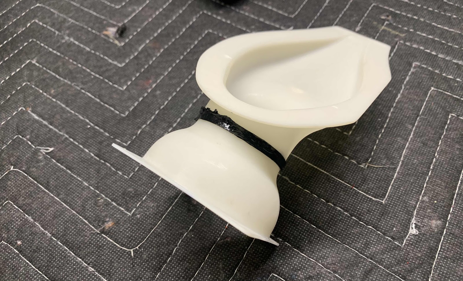
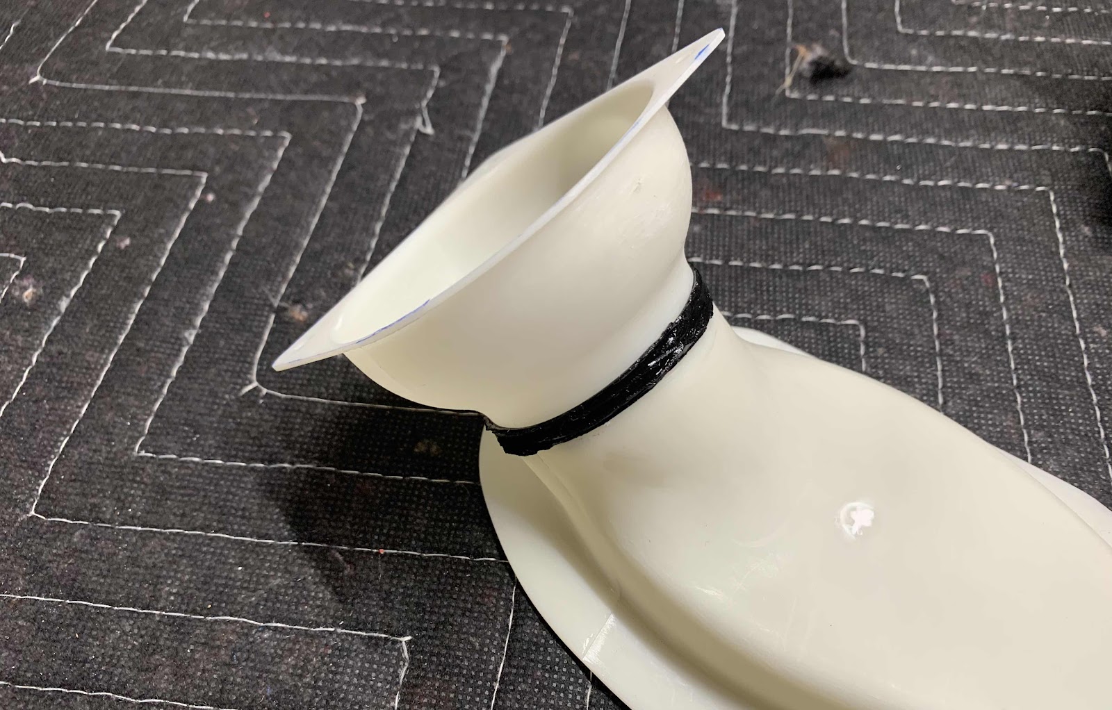
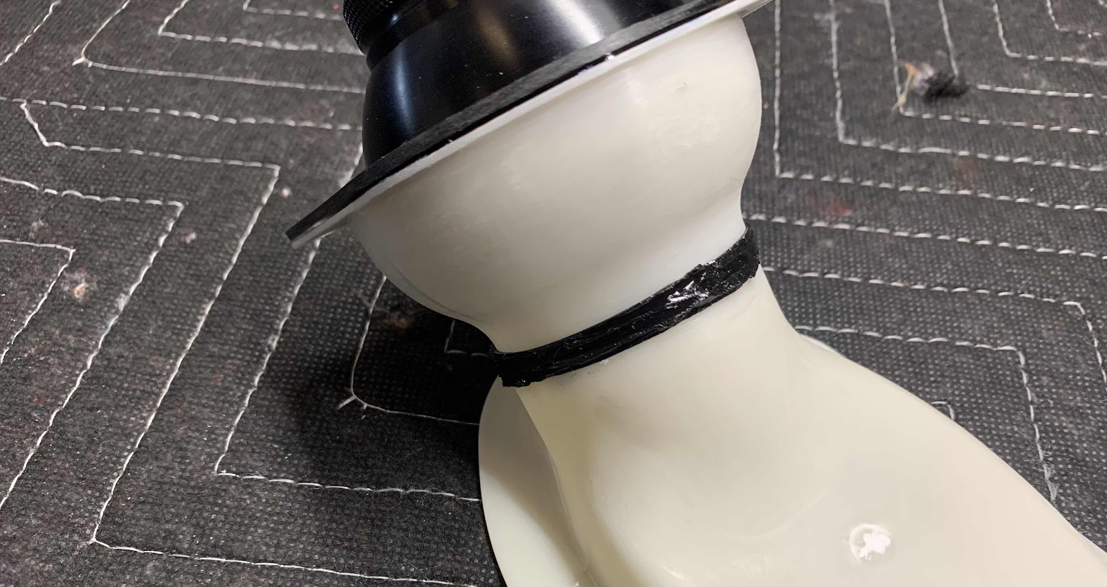
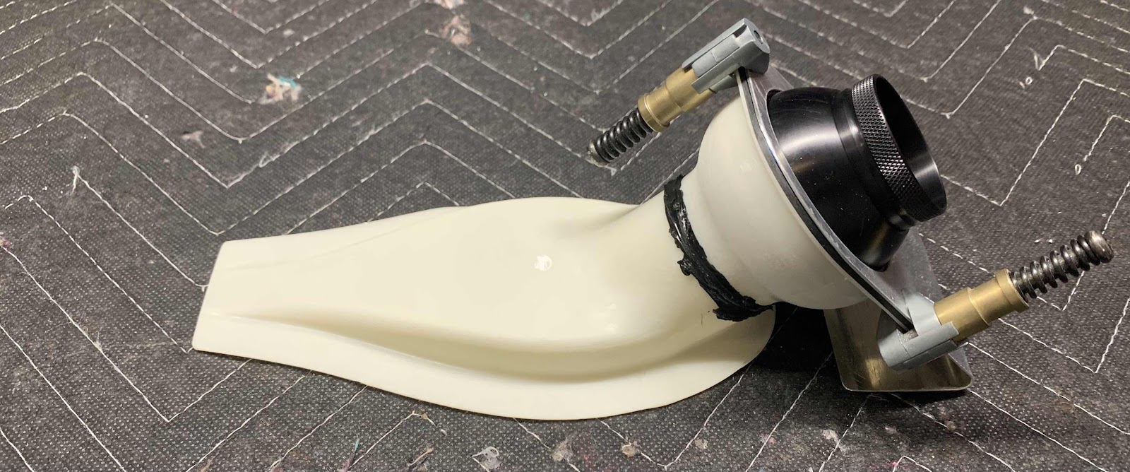
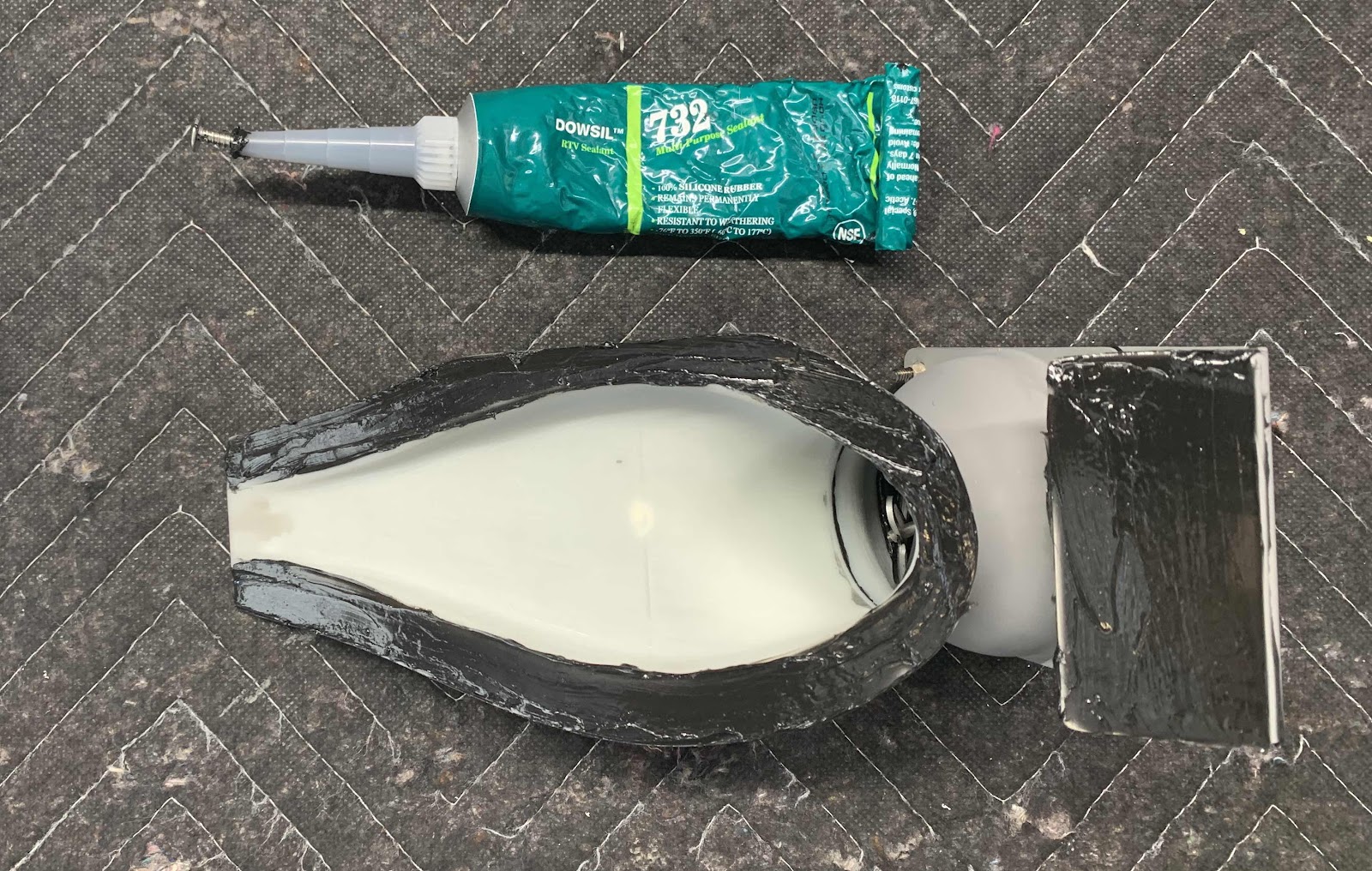
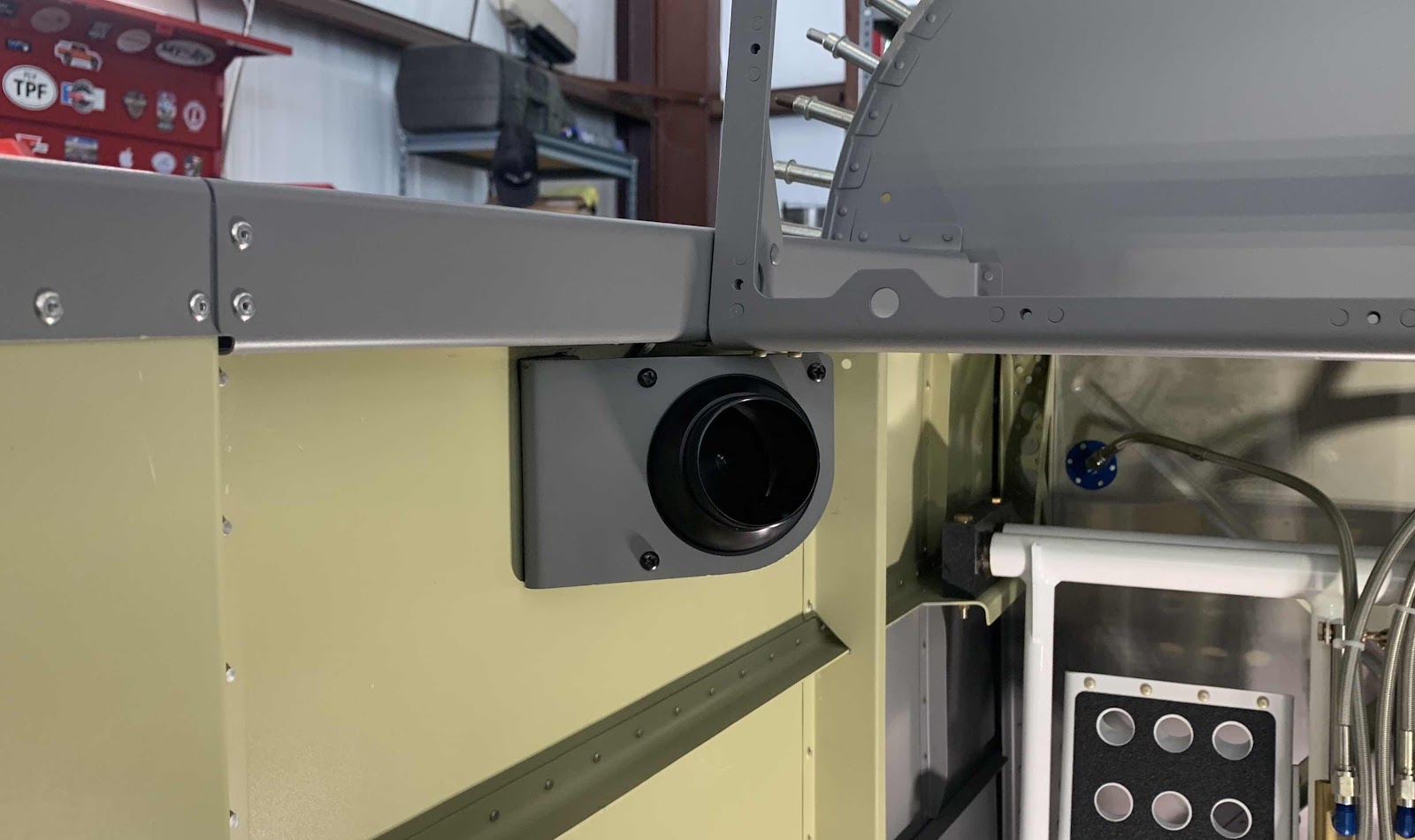
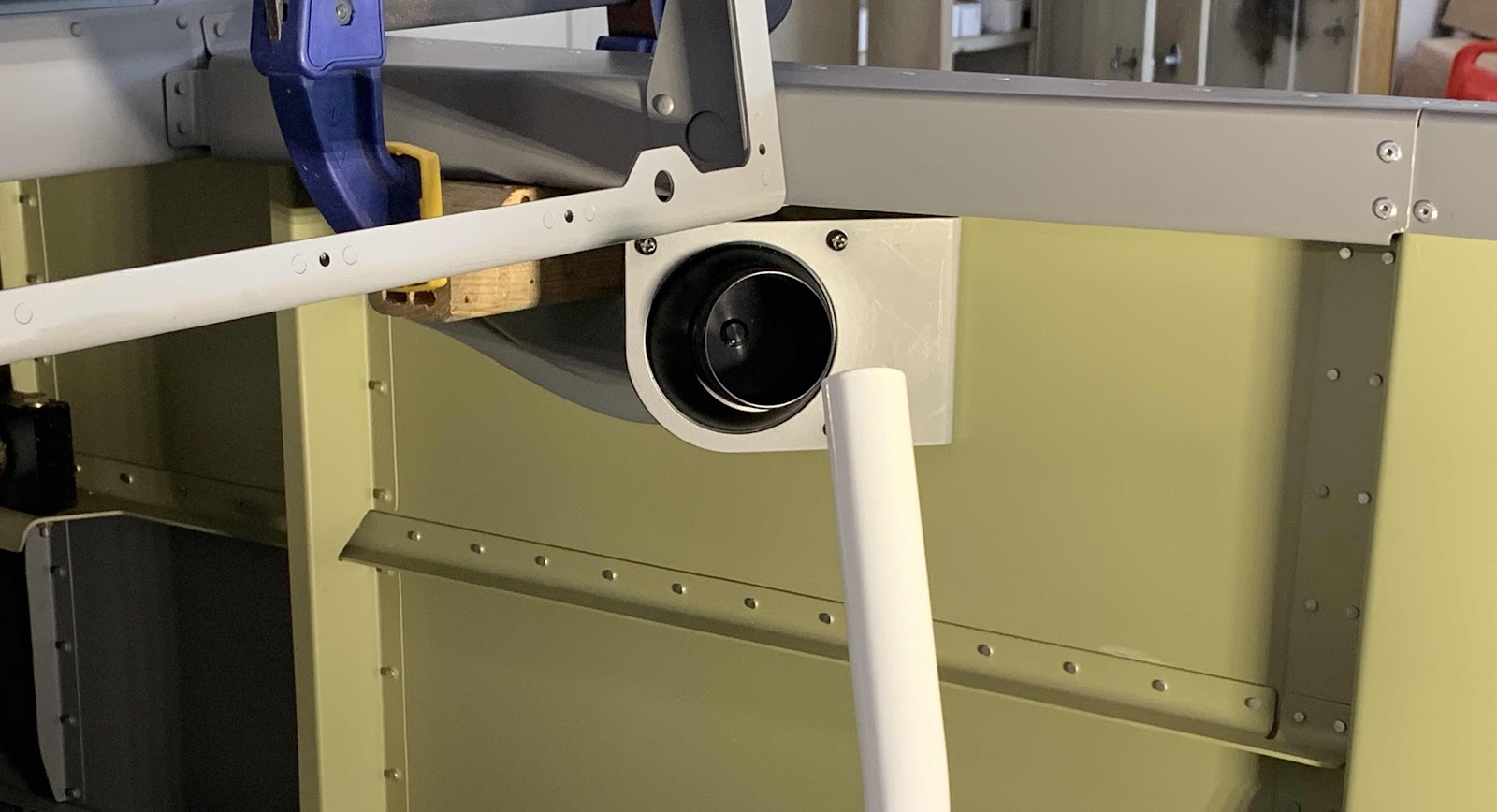
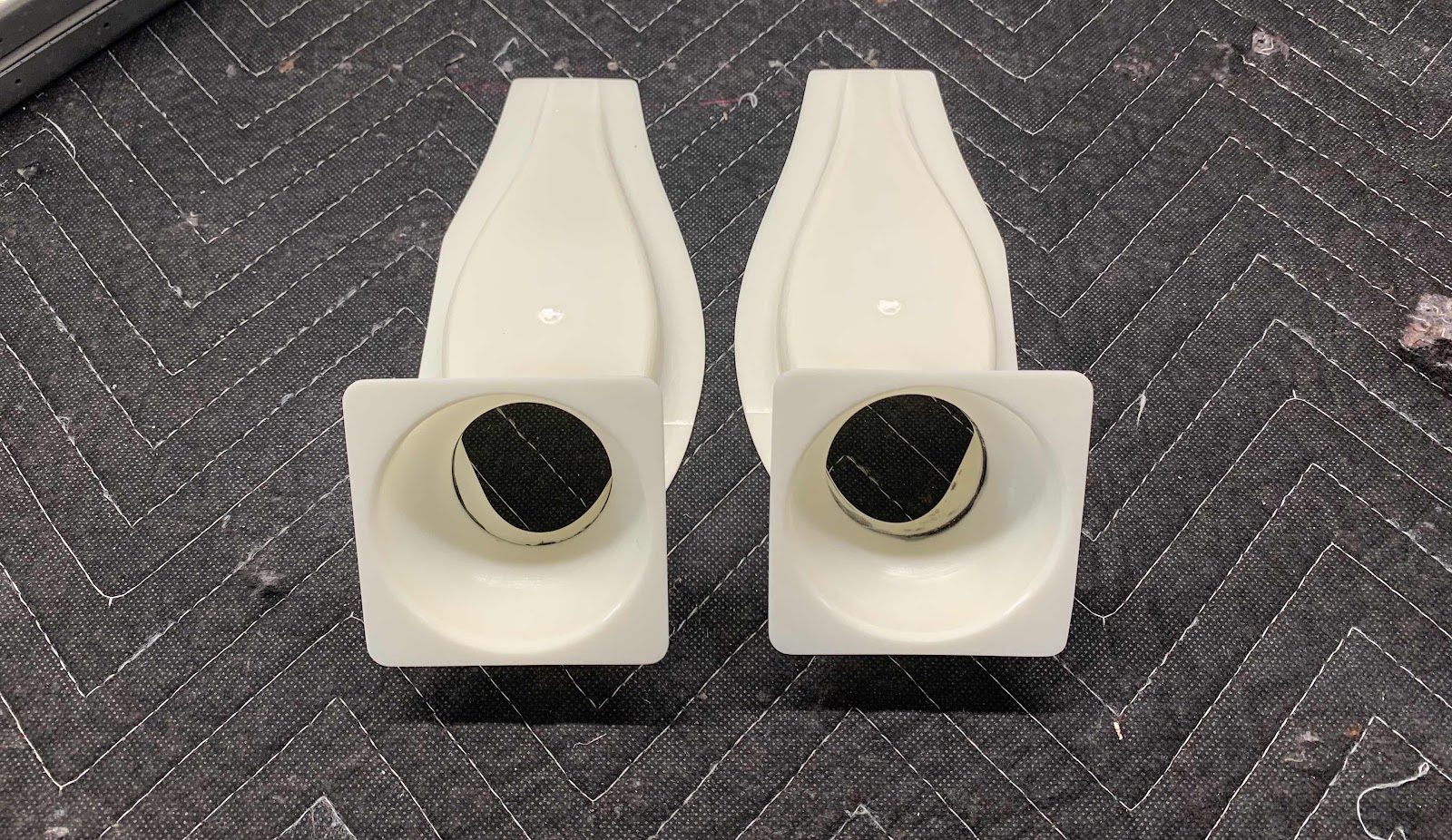
Now, in preparation of applying silicone adhesive and paint, all the surfaces of the two Vents were sanded until there were no shiny areas remaining. Here they are. I still need to apply additional silicone around the black “rings” to fill in some gaps from when the parts were manufactured. After that, they will be ready for assembly and installation on the airplane.
Friday, January 3, 2020
Fuselage, FWD/MID Side Structure (Part 40)
During the last session, the F-01460-L & -R Intercostals were riveted in place with the left and right Side Skins. Now, it’s time to bolt the F-1231D Roll Bar Bases for the final time. Here is an excerpt from the plans showing the hardware used.
This is the forward view of the installed Roll Bar Base on the left side of the plane.....
.....and the aft side. You can see the heads of the AN4-7A bolts used for the installation.

This is the under side of the left assembly showing the installed MS21042-4 nuts. I got a little excited with the torque seal.

The last step on the left side was to install the two AN470AD3-3.5 rivets in the bottom of the Intercostals to the Fuselage Side Ribs.
This is the forward view of the installed Roll Bar Base on the right side of the airplane.....
.....and the aft side. You can also see the heads of the installed AN4-7A bolts used for the installation.

This is the underside of the right assembly showing the installed MS21042-4 nuts. Again, a little excited with torque seal.

Finally, the last step on the right side was to install the two AN470AD3-3.5 rivets in the bottom of the Intercostals to the Fuselage Side Ribs.
Thursday, January 2, 2020
Fuselage, FWD/MID Side Structure (Part 39)
Today, I installed the F-01460-L & -R Intercostals.....and have a confession to make! I previously installed the F-01457-L & -R Gussets to the Upper Longerons AND the F-01405F Brace.....I should NOT have installed the rivets to the Brace (three rivets circled below). The Intercostals will also get riveted in this location. I guess I should have read the plans a little closer.
So, I had to drill out the six rivets (three on each side).

Once those rivets were removed, I could install the Intercostals. Here is what it looks like in the plans.....
.....and the left Intercostal riveted to the left Side Skin and Upper Longeron.....

.....and the right Intercostal riveted to the right Side Skin and Longeron.

Since we were able to install all the remaining rivets in the forward Side Skin a couple of sessions ago, I could now final torque the bolts in the Lower Drag Fitting. Here is what it looks like in the plans.....
.....and on the plane (right side shown.....the left was completed with the left Side Skin).
Wednesday, January 1, 2020
Fuselage, FWD/MID Side Structure (Part 38)
Today, the last rivets in the right forward Side Skin were installed.....almost. In the picture below, you can see the lone remaining rivet (circled) in the underside of the Skin. It can easily be squeezed, so I can do this one by myself during the next session.
The next rivet is the lone CR3212-4-5 Cherry Max rivet (circled below). I needed a total of six rivets, but only had five.....so, I’ve got to get/order a few extras.
Here is the “inside” or shop head side of the rivets.

The “last” few rivets needing to be installed attach the F-14119-R Root Fairing Attach Angle (the left side is shown in the plans excerpt below) to the right Side Skin.
These rivets will be installed during the next work session. Until next time.....
Friday, December 20, 2019
Fuselage, FWD/MID Side Structure (Part 37)
Started today’s session by screwing the F-14144 Seatback Gussetts to the F-01405F Brace. There are a total of four Seatback Gussetts that get installed on the Brace. Pictured below are the the two “inside” Seatback Gussetts. Each of the four Seatback Gussetts are attached to the Brace using two MS35214-31 screws, two NAS1149FN632P washers and two AN365-632A Nylok nuts.
Next, the four F-01405N Seat Back Adjustment Guides previously fabricated are attached to the Brace. Each of the four Seat Back Guides were aligned with the forward edge of the F-01405K Guides (even with the top edge of Seat Back Guides in the picture below) and matched-drilled #30. The #30 holes matched-drilled in the Seat Back Guides were then countersunk to accept the heads the rivets attaching them to Brace. Each of the Seat Back Guides received two AACQ-4-4 Rivets. Here are the two “inside” Seat Back Guides attached the Brace.
This is the whole Brace showing the four Seatback Gussetts and four Seat Back Adjustment Guides screwed and/or riveted into place.

Once the Brace was completed, it was clecoed and riveted to the F-01405D-L &-R Bulkhead Side Channels. This is the right side of the plane showing the manufactured head side of the six AN470AD4-6 rivets installed in this step.....
.....and the shop head side.

Here is the left side showing the manufactured heads of the six AN470AD4-6 rivets.....
.....and the shop head side.
The next step was to cleco the Gussetts into place with the Upper Longerons and Brace as shown below (right side in the first picture, left side in the second) and temporarily install the two bolts (you can see the two bolt heads).
I started the riveting process for the Gussetts, but didn’t get very far. I will pick it up here during the next session.
Subscribe to:
Posts (Atom)