This blog was created to memorialize the building process of my Van's Aircraft RV-14 and to satisfy the requirements for certification in the Experimental Amateur Built Aircraft category. It will also serve as a central location for ME to reference in the future on processes and techniques I used during the build. Additionally, it will allow my family, friends, and other interested builders the opportunity to follow along during my build…..and might be helpful to someone along the way.
Today, we installed the final 10 rivets in the Outboard Aileron Hinge Bracket on the Left Wing. I forgot to take a close up picture, but it’s the 10 rivets in the circle below. This is the same location we completed on the Right Wing on Sunday.
This morning we started bucking rivets in the Inboard and Outboard Top Wing Skins for the Left Wing....lots and lots of rivets!!
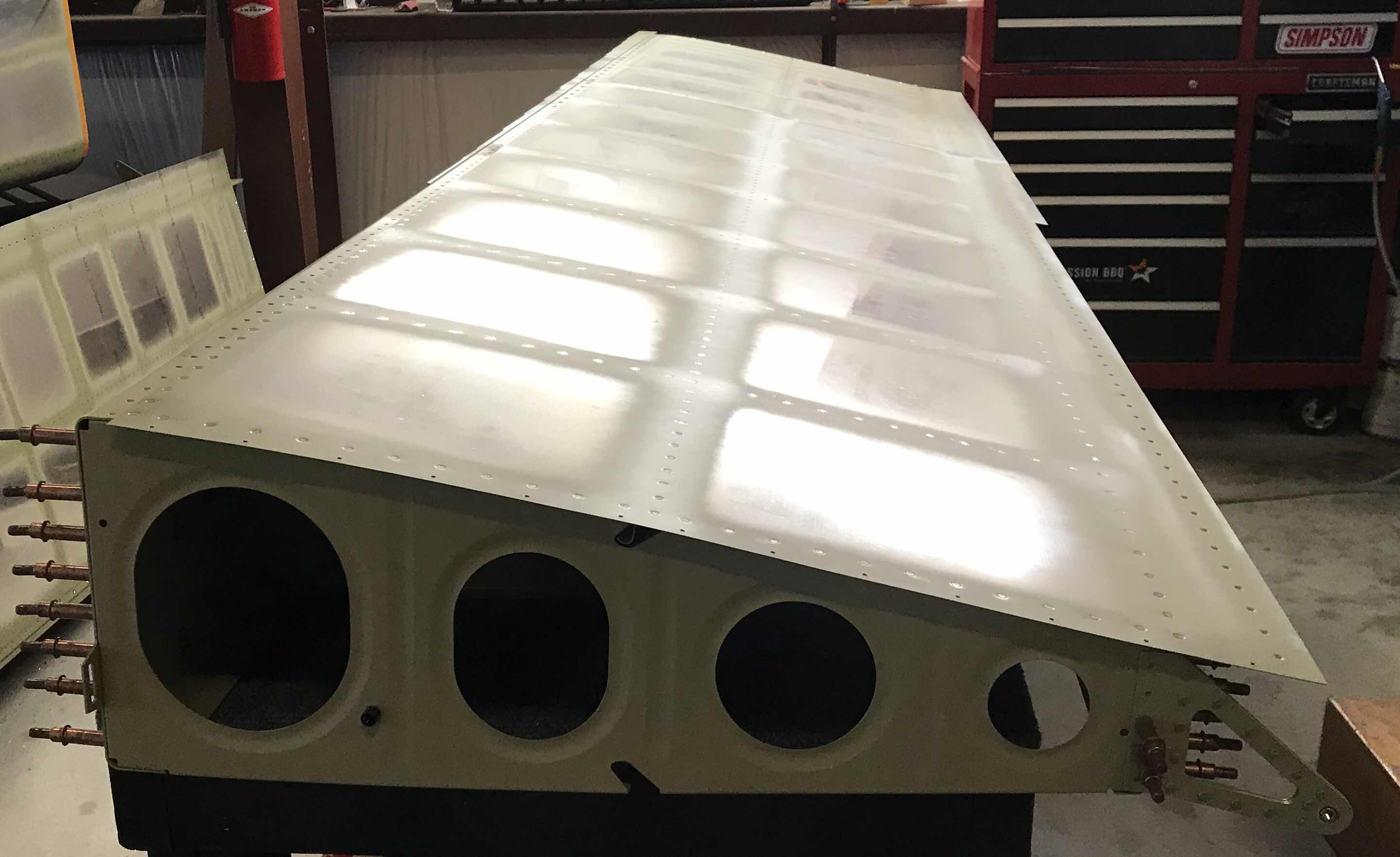
Here is the Left Wing with all the rivets installed, including the J-Stiffener.
Another angle of the Left Wing.....
In this section of the Wing, you can see the two vertical rows of rivets where the Inboard and Outboard Skins overlap. Additionally, this is also the area where the two J-Stiffeners (long and short) overlap.
The inboard section under the Wing Walk showing the J-Stiffener-short installed.
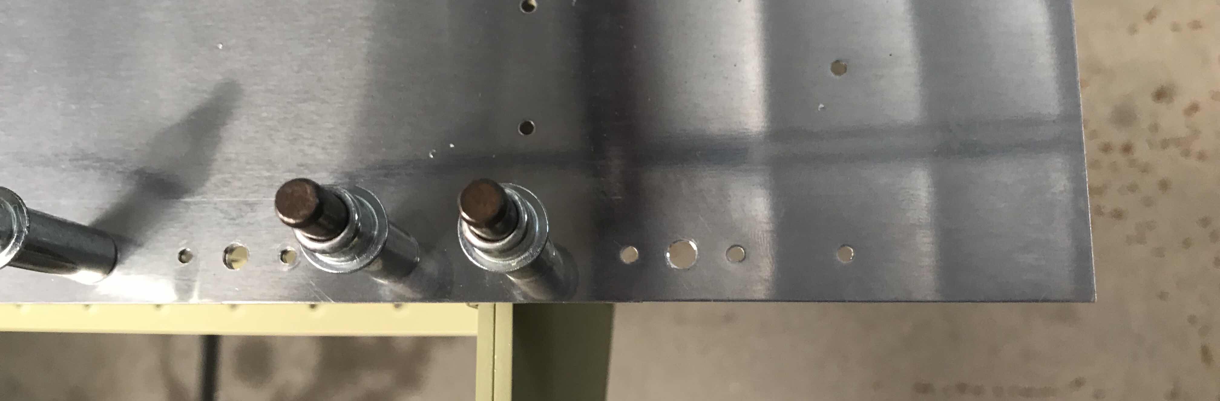
After all the rivets were installed, the seven #19 holes had to be countersunk for the dimpled skin of a #8 screw....you can see them here.....
Tomorrow, we will install the last 10 rivets in the Outboard Aileron Hinge Bracket and Section 16 will be complete!
Yesterday, we set up the countersink cutter and made one countersink (of the seven) to the #19 screw holes for the nutplates on the inboard edge of the Top Skin. Today, we finished countersinking the remaining six holes. Shown below are all seven holes on the inboard edge that were countersunk. They were countersunk deep enough to accept the dimpled skin of a #8 screw. (The countersink on the far left near the Spar was previously countersunk and will ultimately be used as a fuel tank screw.....the hole on the far right is not countersunk, but dimpled).
The last step to complete the Right Wing (for this section), was to install the final 10 rivets in the Outboard Aileron Hinge Bracket Assembly. Five rivets were installed between the Assembly and the Trimmed Outboard Wing Rib (first picture) and five between the Assembly and the Rear Spar (second picture). I tried to follow the “rule of thumb” regarding the manufactured head of the rivet being placed on the thinnest material. However, I was not able to come up with suitable installation method to accomplish this. I initially tried squeezing the rivets with the pneumatic and hand squeezers. I have a 3” standard yoke and 2” Longeron yoke. Neither of the two were usable in this location. I couldn’t shoot the rivets from the “inside” of the Wing because of space issues. So, I made the command decision to install the rivets as you see below. We ended up shooting all 10 with a 3X rivet gun and bucking bar and they came out very nice.....I’m please with the results.
Now that the Right Wing is complete....we moved on to the Left Wing. We were able to install all of the rivets in the Top Inboard Wing Skin before we called this session for the night. We will start with the Top Outboard Wing Skin in the morning.....
We finished riveting the J-Stiffener into the Left Wing. There are only 10 universal rivets left to set in this Wing that connects the Outboard Aileron Bracket to the Rear Spar and Rib. We will set those 10 rivets during the next session.
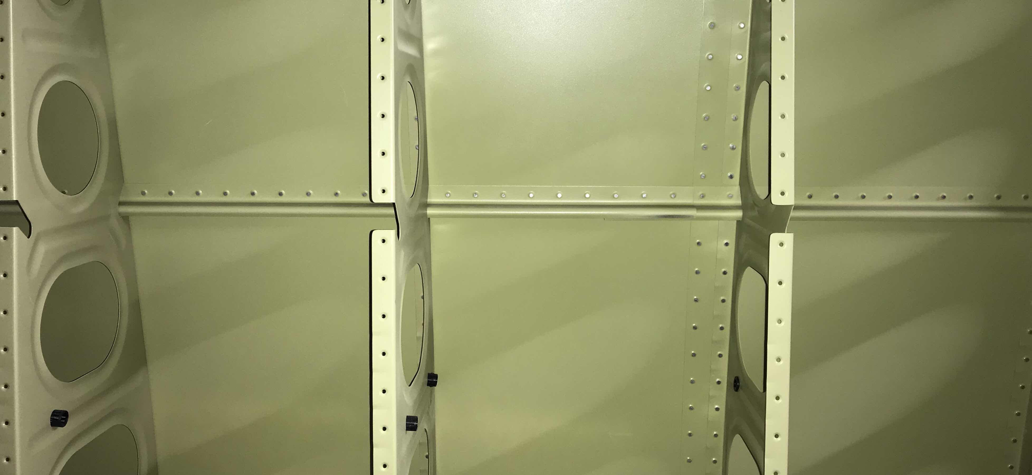
Here it’s he opposite side showing the riveted J-Stiffeners.
Just a close up of a section to J-Stiffener riveted to the Top Skin.
View of the Right Wing laying flat with all the rivets installed.
In addition to the 10 universal rivets mentioned above, seven #8 screw holes will need to be countersunk to fit the Skin of a #8 dimple. In the picture below, the countersunk hole on the right is one of the holes mentioned in this section. (The one one the left was completed in an earlier section).
Well, we finished installing the rivets in the Left Wing Skin (minus the J-Channel).
Below is the inside of the Right Wing showing the Wing Box J-Stiffener-Long and Wing Box J-Stiffeners-Short clecoed into place. As I mentioned before, the J-Stiffeners have not been treated with Alumiprep, Alodine, or Akzo Primer (hence the shiny alumimum).
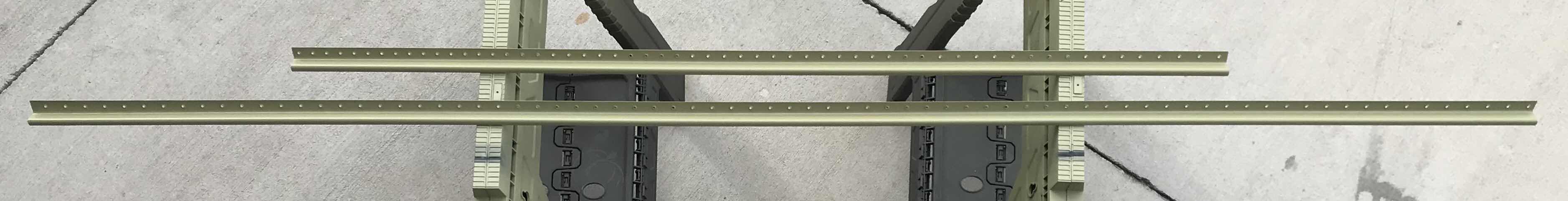
So, in order to finish the Wing, we had to prepare the J-Stiffeners. The -Long and -Short were treated with Alumiprep, Alodine, and Akzo Primer and are shown below drying after being primed.
After they were finished drying, we install them in the Wings.....looks better in Akzo green! They now need to be riveted into place tomorrow.
Below, is the prepared VA-195B Stall Warning Keeper Plate (left) and VA-195A Stall Warning Mount Plate (right). Both pieces were treated with Alumiprep, Alodine and Akzo and will be used to assembly the Stall Warning System in the Left Wing.
After “completing” the Outboard Leading Edges, we shifted our attention back to the Top Wing Skins. All the rivets need to be bucked in both Top Wing Skins. During today’s “second” session, be installed 82 of these rivets. Below is a shot of the area we started working on. Additionally, there will be a J-Channel installed in the horizontal row of holes after the Skins get riveted. In order to get the tightest Skins possible, the plans state to rivet from the center of the Skin and work toward the tips and roots.
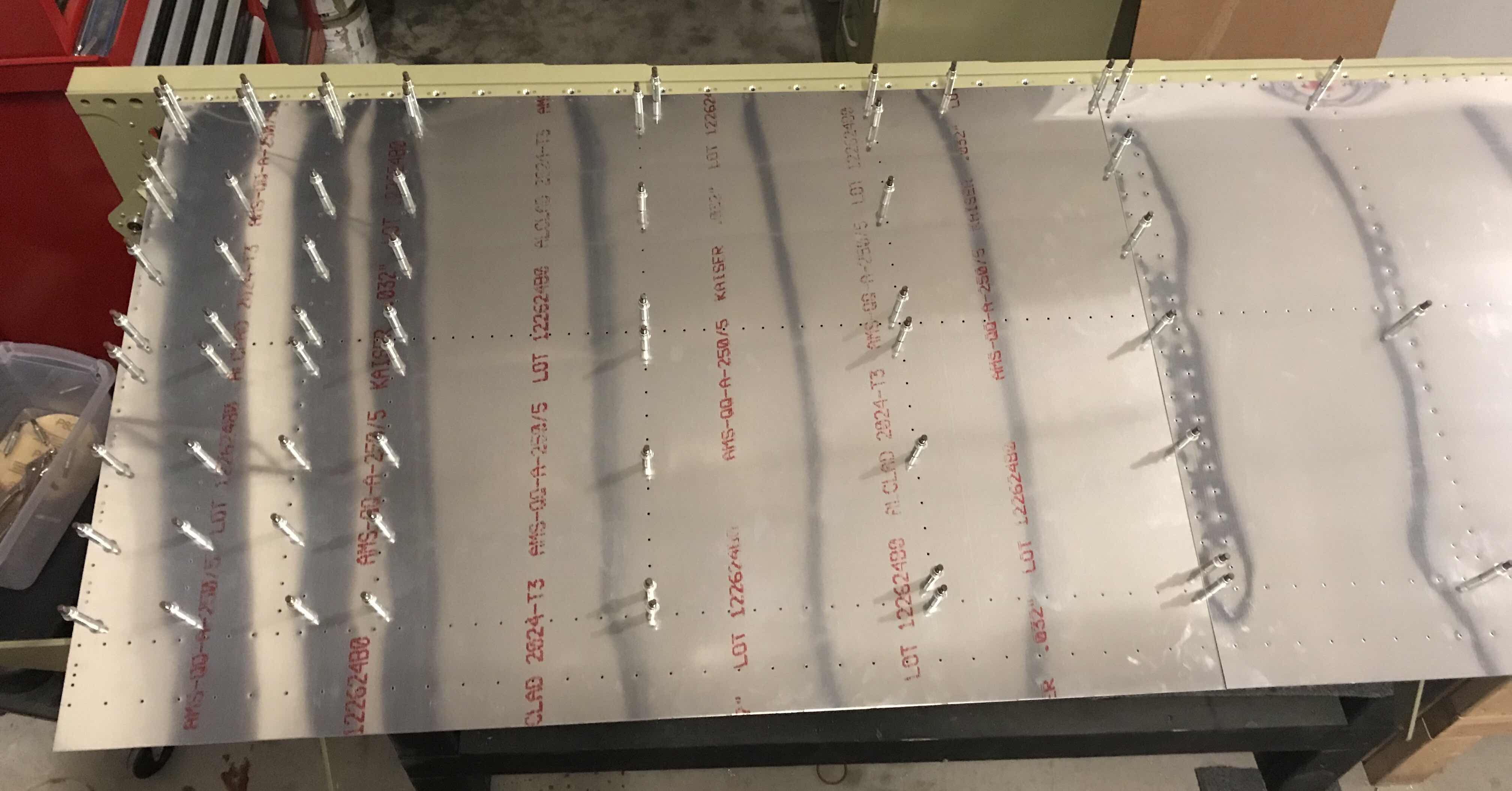
Well, with 1,576 rivets to install in the Top Wing Skins, you don’t turn down free labor from experienced help. My buddy Doc offered to help, so he was hired (and about halfway through, Jeff helped me finish.....I guess he was hired also). We started on the Right Wing with the Inboard Top Wing Skin. As the plans instructed, we clamped the Main Spar down to the work table and placed wood under the Spar at various locations to keep it level. I used a level at several places along the Spar to ensure it remained straight. Additionally, we were cautious not to introduce any warping or twisting to the Wing. Below are a couple pictures of how we did it.....
The plans state in order to get the tightest Skins possible to start riveting in the center of the Skin and work your way to the tip and root. The picture below shows the completed Inboard Wing Skin, minus the horizontal J-Stiffener in the center (which will be installed after the Skins).
Initially, we followed the guidance from the plans and back riveted the Skins using a large bucking bar and extended back rivet set. This method required the Flanges of the Wing Ribs to be slightly “moved” out of the way to keep the set straight on the rivet. As we progressed toward the top and bottom (forward and aft) of the Wing Rib, it became harder to move the Wing Rib. So, we transitioned to the old method of shooting with a rivet gun and bucking bar. This way seemed to work out better and produced a better product.....and went faster. I plan on shooting all the rivets from here on out.
Here is the opposite side of the completed Inboard Wing Skin. If you look closely, you can see the shop heads of the rivets along the Flanges of the Wing Ribs.
On the inboard edge of the Inboard Wing Skin, there are eight nutplates that get installed on the Flange of the Wing Rib. Here you can see seven of them.....one is hidden under the Aileron Torque Tube Support Bracket Assembly.
Well, my free labor had to go.....so, until next time.
I clecoed the Wing Walk Doublers, Top Inboard Wing Skin, and Top Outboard Wing Skin to the Right Wing.....these Skins are now ready to be riveted to the Right Wing.
Following this step, both Wings are now completed to the same point and await the 1,578 rivets (788 per Wing).
The work for this session was actually completed on Saturday, March 24th.
I treated the “inside” of the Skins with Alumiprep and Alodine using spray bottles and foam brushes. On the “outside” of the Skins, I lightly buffed the rivet lines with grey Scotchbrite. After the Skins were sufficiently dried, I sprayed Akzo primer on the entire inside of the Skin and the rivet lines on the outside.
Here is the “inside” of the Top Inboard Wing Skin.....
.....and the rivet lines on the “outside”.
This is the “inside” of the Top Outboard Wing Skin.....
.....and the rivet lines on the “outside”.
Lastly, here are the two Wing Walk Doublers for the Right Wing.
Now that these steps are completed and the Skins have been primed, I will cleco them to the Right Wing and begin the riveting process. At this point, each of the Wings will receive 788 rivets.
I wasn’t able to prime the Top Wing Skins as anticipated, so I moved to the next step in the plans. The top Flanges of the Wing Ribs needed to be dimpled to accept the dimples in the Top Wing Skins. It wasn’t a very time consuming process and it’s now complete. The only “problem” is the Wing Ribs were primed in a previous step in the plans. After the Flanges were dimpled, some of the primer cracked and flaked off. So, prior to riveting the Top Skins, I’ll clean up those areas and touch them up with additional primer.
Now, I’m just waiting for the opportunity to prime the Skins. After that, the Top Wing Skins for the Left and Right Wings will be ready to be riveted.
Tonight, I completed all the dimpling of the #40 holes in the Top Inboard and Top Outboard Wing Skins. I used my hand squeezer with a 3” yoke to dimple the holes I could reach. Then, for the remaining holes, I used the DRDT-2.
Here is the Top Inboard Wing Skin after being dimpled by the DRDT-2.....
.....and the Top Outboard Wing Skin.
And of course, the two Skins with all the #40 holes dimpled.
Not much to show during this session. I cleaned all the edges on the Top Outboard and Top Inboard Wing Skins. As with the Left Wing, I used 120 and 220 grit sand paper to complete the edge work. I also used my edge forming tool to make the necessary lap joints on the Skins.
I decided I had a little more work left in me today. So, I went back to the hangar and deburred all the remaining holes in the Top Inboard and Outboard Wing Skins. I completed one side of the Top Outboard Wing Skin at the end of the today’s earlier session and finished all the holes tonight.
SEE PARTS #2, #3, AND #4 FOR CORRESPONDING WORK ON THE LEFT WING
During today’s session, I started and completed the process of countersinking the common holes between the Top Inboard Skin and the Doublers (FWD & AFT). The two pictures below show the completed process (the first with many clecos still installed and the second with all of them removed). I used the same #40 countersink cutter (and depth) that was used to prepare the Left Wing. (As a reminder, a countersink that is .005 to shallow, is the preferred depth for this step as discussed in the plans).
After completing all the required countersinking, I began the process of removing material from the Top Outboard and Top Inboard Wing Skins. As a reminder, the excerpt below describes this process. As with the Left Wing, I used a small hand file, 80 grit sandpaper, and 220 grit sand paper to achieve the required results.
This shows the overlap of the Inboard and Outboard Skins PRIOR to any material being removed. The Fuel Tank Skin will be attached at this location and has a thickness of .032”. So, the idea is to remove material from each of the Top Skins to make a smooth transition at this location. You can also see the scrap piece of .032” aluminum I used as a guage for the proper thickness.
I did not quite get the final result I wanted to, so I will pick it up here during the next session.
In my previous post (Part #9), I completed the work on the Left Wing (for this section anyway).....minus installing the rivets. I have decided to wait on riveting the Inboard and Outboard Wing Skins on the Left Wing until the Right Wing is completed to the same point. Then, I can complete this section for both wings at the same time....so to speak.
The Top Inboard and Top Outboard Wing Skins on each Wing will receive 788 rivets. So, armed with this knowledge, I consulted myself and determined it was “better” to install all 1,576 rivets together. That’s ALOT of rivets! Anyway, moving on to the Right Wing.
SEE PARTS #1 & #2 FOR CORRESPONDING WORK ON THE LEFT WING
As with the Left Wing, the work on the Right Wing will start with the Top Inboard Wing Skin and the Wing Walk Doublers-FWD and AFT. I began by removing the blue protective plastic from the the Top Inboard Skin, Top Outboard Skin and the two Wing Walk Doublers. Next, I clecoed the Top Inboard Skin and Wing Walk Doublers to the Right Wing as shown in the picture below. (I also clecoed the Top Outboard Skin, more or less, to check the fit).
Once clecoed into place, all the common #40 holes to the Top Inboard Wing Skin and Doublers (FWD and AFT) were Final-Drilled.....which included the rivet attach holes for the nutplates.
The center nutplate holes were then Final-Drilled to #19. In the picture below, you can see where two of the nutplates will be installed. There will be a total of eight nutplates (just like on the Left Wing).
If you look closely below, you can see all eight nutplate locations.....look for the larger #19 center holes in the bottom row of clecos.
Now that I have all the Skins primed and ready for riveting, I took a few minutes and sprayed some touch up primer in the Wing Ribs (where I scratched it with the rivet gun or bucking bar) with my airbrush gun. After that was completed, I clecoed into position, for the final time, the Top Inboard Wing Skin.....
....and Top Outboard Wing Skin to the Left Main Spar, Wing Ribs, and Left Rear Spar. If you look at the left side of the picture above, you can see two rows of clecos running forward and aft. This is the location where the Top Inside and Top Outside Skins will overlap. The row on the right side will be riveted to the Wing Rib Flange underneath and the row on the left will just rivet the Skins together.
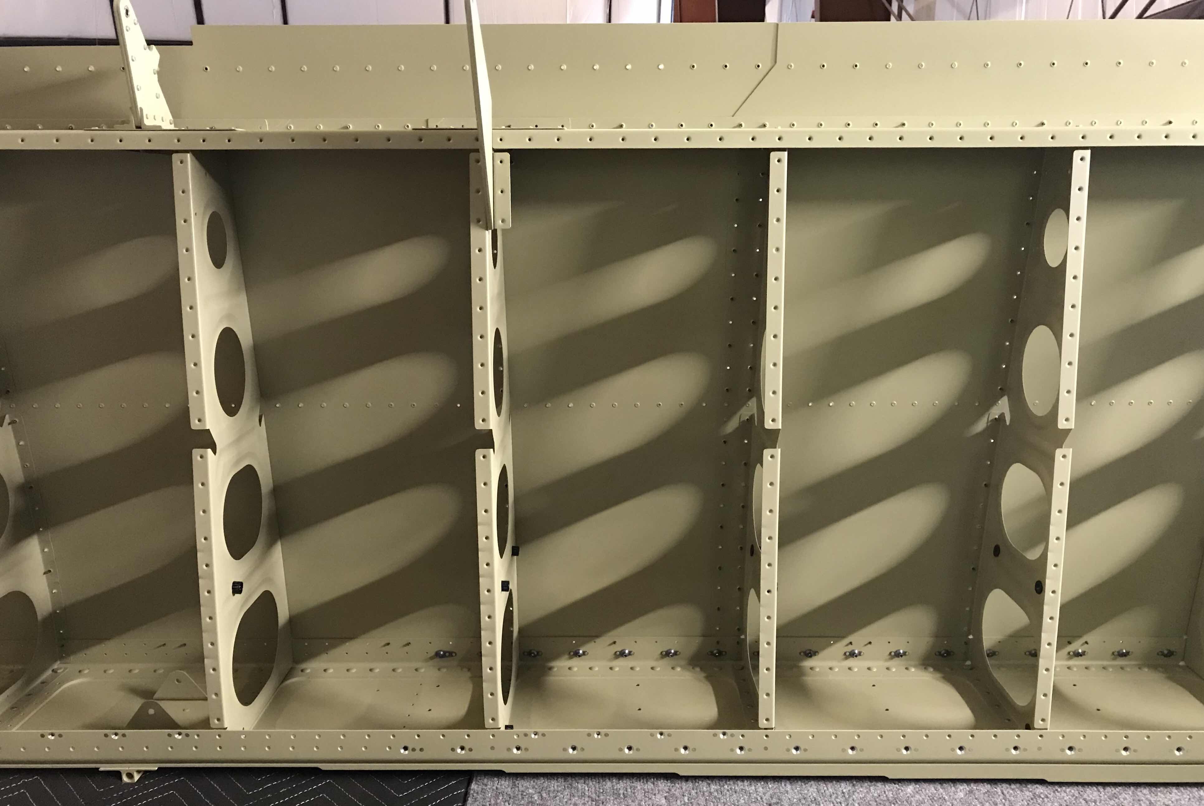
Here is a view of the whole Left Wing with both Skins clecoed into place.
I stood the Left Wing up on the Main Spar to make sure all the clecos were installed in the correct positions and in the right holes. On the right side, you can see the four Wing Ribs that make up the Wing Walk area.