Showing posts with label Section 06-Vertical Stabilizer. Show all posts

Sunday, October 29, 2017

Empennage, Vertical Stabilizer (Part 17)

I wasn’t able to publish this post prior to midnight, so this work session was actually completed on Saturday, October 28, 2017.  

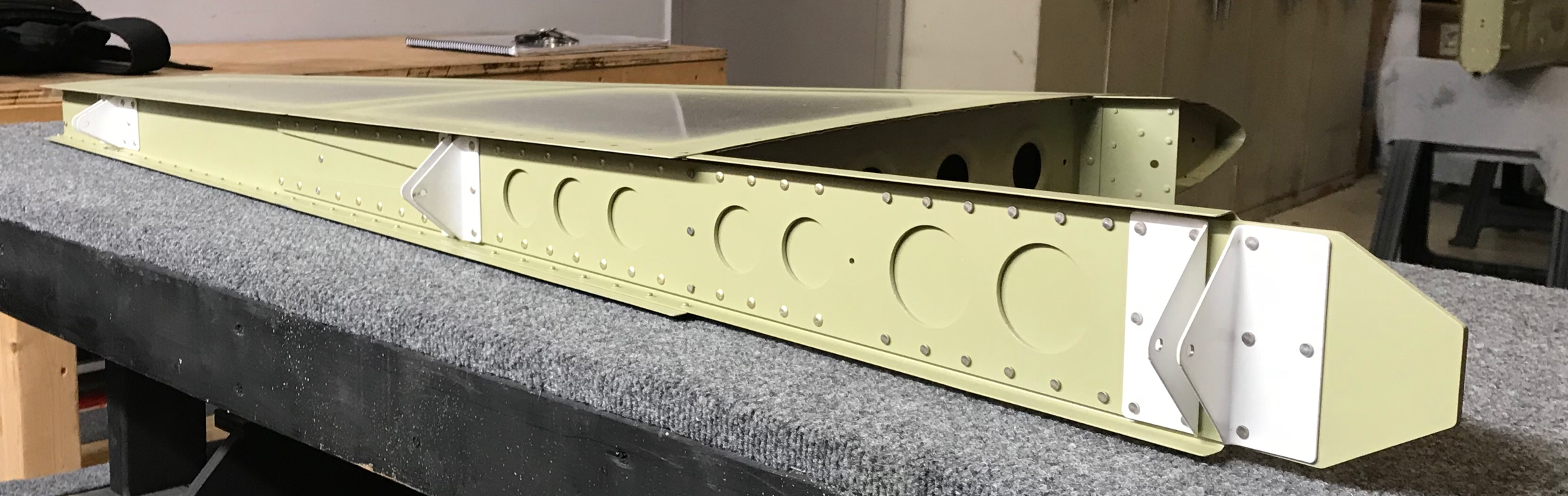
I primed the Rear Spar and Rear Spar Doubler on Friday night and let it dry overnight.  To complete the new Spar on Saturday, I riveted the Rear Spar, Spar Doubler and Hinge Brackets using the hardware called out in the plans.  The three pictures below show the completed Vertical Stabilizer with the newly completed Spar Assembly.....minus the errant hole!!!!!


I did make one change from the “first Spar” to the “second Spar”.  The build plans call for AN426AD3-3.5 rivets to be used to attach the Skin and the Rear Spar (which is what I used on the first Spar).  However, I used AN426AD3-4 rivets on the second Spar.  I used a rivet guage and measured both rivets.  The AD3-3.5 rivets measured just a little short and the AD3-4 measure just a little long.  I set one of the AD3-4 rivets and liked the result much better than the shorter ones.  So, I used them on the rest of the assembly.  Very pleased with the outcome. 


Section Complete (Take Two)

Wednesday, October 25, 2017

Empennage, Vertical Stabilizer (Part 16)

I haven’t had the most desirable conditions to prime the Spar and Spar Doubler, so to keep moving forward.....I began removing the “bad Spar”.  The picture below shows the Vertical Stabilizer with the Spar/Spar Doubler attached.

This is the same Vertical Stabilizer after the 72 rivets (64 AN426AD3-3.5, two AN470AD4-4, three AN470AD4-6, and three LP4-3 rivets) were removed.  And guess what.....I didn’t damage any of the holes!!  That’s a victory right??

Over the next day or so, I will prime the Spar/Spar Doubler, rivet the two pieces together, and install it on the Verical Stabilizer.

Saturday, October 21, 2017

Empennage, Vertical Stabilizer (Part 15)

Well, from reading my previous posts, you know I put a hole where it didn’t belong.  I received great advice from the big brains on the Van’s Airforce Forums and from Van’s Aircraft on how to “fix” my problem.  However, like one previous time before, I feel like it’s a bandaid fix for a bonehead mistake I made!  So, after much deliberation, I decided to rebuild the Vertical Stabilizer Spar and “get rid” of my problem.  I ordered the replacement parts from Van’s and they are shown below. 

I re-ordered the VS-803PP Rear Spar, VS-410, 411, 412 Hinge Brackets, VS-808PP Rear Spar Doubler, and the F-01412 A & B Bulkheads.  At this point, I am definitely going to rebuild the Rear Spar Assembly, but I haven’t made a decision regarding the Bulkheads (two pieces on the bottom). 

So, let’s begin.....

I started by Final-Drilling #12 the six Rudder attach holes in the Hinge Brackets.  Then, the whole Spar Assembly was clecoed together, the Hinge Brackets were Final-Drilled #30, the Rear Spar and Spar Doubler were Final-Drilled to #30, and two holes were Match-Drilled #30 from the Spar/Spar Doubler to the upper Hinge Bracket off the VS-410PP (lower assembly, upper bracket).

Finally, I disassembled all parts and deburred.....including the appropriate edge work.  The next step was to dimple the Rear Spar to accept a dimpled Skin.  Just like on the previous build, I used the Substructre Dimple Dies for this part.

The next piece of work was to Machine Countersink the #30 holes in the Rear Spar Doubler that attach the Rear Spar to the Doubler and dimple the corresponding #30 holes in the Rear Spar.  This area will be joined together with AN426 flush head rivets and ultimately attach to the Rear Fuselage. 

Finally, I gave both pieces a bath with Alumiprep and Alodine and hung them up to dry.  I will prime and assemble the two pieces tomorrow.  This picture shows the Rear Spar Doubler after getting the #30 countersinks, Alumiprep, and Alodine.  It’s hanging up to dry with the Rear Spar. 


Thursday, March 9, 2017

Empennage, Vertical Stabilizer (Part 14)

**********MILESTONE #1**********

Today, my buddy Jeff and I shot the final four rivets to complete the Vertical Stabilizer.  It feels very satisfying to see the first REAL part of the airplane completed.
 

Section Complete

Wednesday, March 8, 2017

Empennage, Vertical Stabilizer (Part 13)

Today I riveted the Rear Spar to the Vertical Stabilizer assembly.  However, I was not able to finished before I had to go to work.  I have only four more rivets and then the Vertical Stabilizer will be done.  The Tip Rib was attached to the Rear Spar using AN470AD4-4 rivets, the Root Rib was attached using AN470AD4-6 rivets, the Rib was attached with LP4-3 rivets and the remaining Rear Spar was attached to the Skin using AN426AD3-3.5 rivets.

I will shoot the four remaining rivets attaching the upper leading edge of the Skin to the Tip Rib.  I will attach some "finished" pictures with my post tomorrow.


Empennage, Vertical Stabilizer (Part 12)

My buddy Jeff had some time to help me rivet the Vertical Stabilizer together.  So, tonight I shifted back to the Vertical Stabilizer.  Following the plans, we started riveting the Skin at the intersection of the VS-702 Front Spar and the VS-707 Rib with a AN426AD3-4 rivet.  We then riveted toward the Tip and then toward the Root using AN426AD3-3.5 rivets.  The Skin was then riveted to the VS-704 Root Rib, VS-705 Nose Rib, and the VS-706 Tip Rib also using AN426AD3-3.5 rivets. 
 

Vertical Stabilizer being riveted together.


Moving along with the plans, next was to cleco the Rear Spar Assembly to the Vertical Stabilizer.  Once that was completed, I closed up shop and went home.  I will rivet on the Rear Spar and finish the Vertical Stabilizer tomorrow.
 
Clecoing the Rear Spar to the Vertical Stabilizer assembly.

Thursday, March 2, 2017

Empennage, Vertical Stabilizer (Part 11)

I had to make a few minor corrections to previous work on the Vertical Stabilizer.  In the picture below you can see six pieces of orange tape around the bottom of the assembly (there are also six pieces of tape on the opposite side of the assembly in corresponding locations).  The tape covers hole locations in the Skin that DO NOT get dimpled or riveted during this portion of the build.  Per the instructions, I did nothing to these 12 holes (six on either side).  
 
Over the past few days, I started to wonder about the 12 corresponding holes in the Ribs (five in each side of the Root Rib and one in each side of the Nose Rib).  In Part 6, I dimpled these holes with Substructure Dimple Die when I completed the dimpling of all the other pieces.  Since I am about to permanently rivet the Skin onto the Vertical Stabilizer skeleton, I wanted to verify how these holes should be.

I emailed Van's Aircraft at support@vansaircraft.com to inquire.  Sterling responded very quickly and informed me that I shouldn't have dimpled the 12 holes in the Ribs.  However, it wasn't a big deal.  He suggested I flatten the dimples out the best I could with flush sets in my squeezer and build on.  He also stated these holes would be drilled out to larger sized holes later in the build and it would eliminate 90% of the dimple anyway. 

 (*****I found in Section 12 what Sterling was talking about.  Those 12 holes will be drilled out to #27 in order to attach the empennage fairing*****)  So, I flattened out the 12 dimples as Sterling suggested and will rivet the Skin to the Vertical Stabilizer skeleton tomorrow.

Monday, February 27, 2017

Empennage, Vertical Stabilizer (Part 10)

Ummmm.....Well.....Damn it!  Yesterday, I posted a picture showing the Front Spar, Rear Spar, and the four Ribs clecoed together for riveting.  Today, I riveted EVERYTHING together.  Despite seeing a note in the plans, reading the note in the plans, circling the note in the plans, and re-reading the note in the plans (several times).....I didn't comply with the note.  What does the note say.....
 
The NOTE says:  "Take care to assemble the parts in the order given in the step by step instructions"
The INSTRUCTIONS say, "Rivet all of the Ribs to the FRONT SPAR using the rivets called out in Figure 1".  Well, I did all that (I guess you could also argue that I didn't do all that).....and also riveted the Rear Spar.....WRONG!  

So, now I have to fix it.  Not a BIG deal, but still a goof on my part!  After drilling out the eight rivets and removing the Rear Spar, below is the Front Spar, Tip Rib, Rib, Root Rob, and Nose Rib all riveted together.....as originally called for in the plans.  As it turns out, you can't reach the inside of the Vertical Stabilizer and rivet the Skin to the Front Spar.....with the Rear Spar IN THE WAY!
 

The two pictures below show the areas inside the Vertical Stabilizer I will need to access in order to rivet on the Skins.  An AN426 rivet will go into every hole that you see a cleco.  To set the rivets, a bucking bar will need to be used in this inside area.  Again, you would not be able to access this space with the Rear Spar attached to the assembly.
 
 
This is the bottom section of the Vertical Stabilizer showing the end of the Front Spar, the Root Rib, and the Nose Rib.  The orange tape you see on the Root Rib is marking holes (covering them actually) that will not recieve rivets during this portion of the build.
 
After fixing my goof, I finally have the whole assembly clecoed together and ready to have the Skin riveted to the Vertical Stabilizer skeleton.  Notice there are no clecos on the left side of the Skin......can anyone guess what goes there?.....you got it, the Rear Spar!
 

Here you see me clecoing the Skin to the Vertical Stabilizer skeleton in preparation for riveting.

Sunday, February 26, 2017

Empennage, Vertical Stabilizer (Part 9)

I started today by riveting the Front Spar Doubler to the Front Spar.  This was a previous step in the plans, however, I skipped the riveting in order to epoxy prime these pieces with the rest of the Vertical Stabilizer.  The Rudder Hinge Brackets, Rear Spar, and Rear Spar Doubler were then riveted together with a combination of flush and universal head rivets.  This picture shows all the pieces clecoed together prior to riveting.
 

Once everything was clecoed, I riveted them together using the pneumatic squeezer.  The Rear Spar assembly used five different sizes of AN426 Flush rivets and AN470 Universal Head rivets.  Below are examples of the two types of rivets used to complete the Rear Spar assembly.
 
 
The Front Spar, Rear Spar, Tip Rib, Rib, Root Rib, and Nose Rib make up the Vertical Stabilizer skeleton.  These will be the next pieces to get riveted together and is shown clecoed together below.
 
This is a different view of the Vertical Stabilizer skeleton.  You can see the aft portion of the Rear Spar which contains the Rudder Hinge Brackets in white.
 
Lastly, I epoxy primed the rivet seams on the outer Skin in preparation for riveting to the Vertical Stabilizer skeleton.  Since it was a relatively small job, I used a Preval Spray System purchased at The Home Depot to spray the primer. 

The video covers the first half of the Rear Spar, Rear Spar Doubler, and Rudder Hinge Brackets assembly.


The video covers the second half of the Rear Spar, Rear Spar Doubler, and Rudder Hinge Brackets assembly, the assembly of the Vertical Stabilizer skeleton, and the preparation of the outer Skin.

Friday, February 24, 2017

Empennage, Vertical Stabilizer (Part 8)

No progress in the last few days because I was waiting on the Akzo Epoxy Primer I ordered from Aircraft Spruce & Specialty Company.  The Akzo arrived yesterday, so tonight I primed the eight pieces that make up the Vertical Stabilizer skeleton.
 

Monday, February 20, 2017

Empennage, Vertical Stabilizer (Part 7)

This afternoon I finished machine countersinking and dimpling the last few holes on the Rear Spar and Rear Spar Doubler.  The #30 holes in Rear Spar Doubler needed countersinking for AN426AD4 rivets.  Then, the corresponding holes on the Spar were dimpled with the DRDT-2.  Up until now, all the dimpling on the Vertical Stabilizer was for AN3 rivets, which uses a 3/32 Dimple Dies.  Because the Rear Spar and Rear Spar Doubler will be using bigger AN4 rivets, 1/8 sized Dimple Dies were used to dimple the Rear Spar.  Now, all the drilling, deburring, countersinking, and dimpling is complete on all the components that make up the Vertical Stabilizer.  

Now moving on to corrosion resistance!! There have been numerous debates and discussions among RV builders about corrosion resistance....how much, how little, what products to use, processes to use, best practices, etc.  Taking into account all the information and advice I've found online, and talking to many different RV builders, I have decided on the following corrosion resistance process and products on my airplane:

1.  Alumiprep:  Bonderite C-IC 33 Aero Acid Deoxidizer by Henkel.  It is also known as Turco Alumiprep 33 and is a phosphoric acid based cleaner, brightener, and pre-paint conditioner for aluminum.

2.  Alodine:  Bonderite M-CR 1201 Aero Chromate Coating (Alodine 1201) by Henkel.  Alodine is a chromic acid based coating chemical that produces a chrome conversion coating on aluminum and it's alloys.  The chrome conversion coating is very good for corrosion resistance and paint adhesion.  The chrome conversion coating forms a gold color on the aluminum being treated. 

3.  Epoxy Primer:  Akzo Fast Drying Interior Epoxy Primer by Akzo Nobel.  This is a chemically cured 2-component epoxy primer that provides maximum protection from various chemicals, hydraulic fluids, aviation fuels, and corrosive media.  Here is the Tech Data Sheet for the primer.  

The four pieces in the picture below were prepared as described in this EAA Hints for Homebuilders video.  The pieces were cleaned by being dipped in Alumiprep 33 (diluted 50% Alumiprep, 50% water) for two minutes, rinsed with fresh water, dipped in Alodine 1201 (no dilution)  two minutes for the chrome conversion coating, rinsed with water again, and finally hung up to dry.
 

The four larger pieces in the picture below were prepared by the same process.  However, due to their larger size, the Alumiprep 33 and Alodine 1201 were sprayed on each piece with a squirt bottle.  The Alumiprep 33 was sprayed on the aluminum piece and then scuffed with a grey Scotch Brite pad.  The Alodine 1201 was sprayed on the aluminum piece and then brushed on with a foam brush.  Each piece was rinsed with water between the application of each product and then again at the end.

Countersinking and dimpling the final holes in the Rear Spar and Rear Spar Doubler.  Also, you see the corrosion resistance process for the four smaller Vertical Stabilizer pieces.

Empennage, Vertical Stabilizer (Part 6)

Not a whole lot of visual progress today; however, a lot was accomplished.  I dimpled the Skin, Front Spar, Rear Spar, Root Rib, Nose Rib, Tip Rib, and Rib for AN426AD3 flush mount rivets.  I used the DRDT-2 for most of the Skin, but had to use the Pneumatic Squeezer for a few holes near the bend of the leading edge.  I used the pneumatic squeezer for all the Spars and Ribs.  Below, you can see a few of the dimples in the Skin.
 

As I indicated on a previous post, I decided to use the Substructure Dimple Die Set from Cleaveland Aircraft Tool.  I've been pleased with the results and will use them throughout the airplane build.  I also plan on using the Tank Skin Dimple Die Set on the fuel tank skins when I build the wings.  Here is a video from Mike at Cleaveland Aircraft Tool discussing the two Die Sets.  I also had to use the Tight Fit Dimpling Fixture to get to the two forward most flange holes on the Tip Rib.  There was not enough space to get the pneumatic squeezer or the DRDT-2 into for the dimple.  

Like I said, not a lot of visual progress, but all of the parts below are now dimpled.  Tomorrow I will machine countersink the #30 holes in the Spar Doubler for the AN426AD4 rivets.
 

Dimpling the Skin with the DRDT-2 and Pneumatic Squeezer.


Dimpling the Spars and Ribs with the Pneumatic Squeezer.

Sunday, February 19, 2017

Empennage, Vertical Stabilizer (Part 5)

Yesterday's work included drilling, drilling, and more drilling.  Then, was followed by deburring, deburring, and more deburring.  The Rudder Hinge Brackets, Rear Spar, and Rear Spar Doubler were all final drilled.  The Tip Rib, Root Rib, Nose Rib, and Rib flanges were adjusted to match the taper of the Spars and Skins.  (The precision from the Van's factory only required a few very minor adjustments).  

The corners of the Nose Rib and Tip Rib were radiused to allow the Skin to fit better and more easily.  All four Ribs were then fluted to straighten the web of the rib.  None of the Ribs required much work to straighten.  The Ribs were then fitted to the Spars and final drilled to the Spar attach holes.

Lastly, the Skin was fitted and clecoed to the Vertical Stabilizer skeleton.  Again, only very small adjustments were required to achieve the perfect fit.  All the Skin to Vertical Stabilizer assembly holes were then final drilled.  

The entire Vertical Stabilizer was then completely disassembled and all the parts were then deburred.
 

The video below covers all the fitting, drilling, and deburring of all the pieces, except the Skin.


The video below covers the Skin deburring.

Saturday, February 18, 2017

Empennage, Vertical Stabilizer (Part 4)

I started today by final drilling the three Rudder Hinge Brackets and all the Rear Spar/Spar Doubler holes.  Next was to flute (straighten the web area) the Rib, Root Rib, Nose Rib, and Tip Rib.  After the four ribs were properly fluted, they were final drilled and clecoed to the Front and Rear Spar to form the skeleton of the Vertical Stabilizer.
 

Once the skeleton was formed with the Ribs and Spars, the Outer Skin was fitted and clecoed into place.  The RV-14 kit from Van's is manufactured so precisely, I only had to make a few minor adjustments for an exact fit.  The picture below shows the Vertical Stabilizer clecoed together with the Outer Skin attached to the skeleton.


Friday, February 17, 2017

Empennage, Vertical Stabilizer (Part 3)

Flush riveting requires that the hole receiving the rivet be countersunk by one of two methods.....dimpling or machining.  

Dimpling:  Used on material with a thickness less than .040.  Dimpling re-shapes the aluminum around the hole, but doesn't remove any material.  Dimple Dies are used in the dimpling process and come in specific sizes for the fastener being installed.
 

Machine Countersinking:  Used on material with a thickness of .040 (or greater).  To machine countersink, you will use a Threaded Micro Stop Countersink attached to a hand drill/drill press and a Countersink Cutter.  The countersink cutters are also size specific to the fastener being used.


Last night, I used the DRDT-2 to dimple the appropriate holes in the Front Spar Doubler and Front Spar.  The next step is to rivet the two pieces together.  However, I am going to hold off on doing that right now because I first want to epoxy prime the two pieces.


Next, I final drilled the Rudder Attach Holes in the three Hinge Brackets (they are in white in the picture below) to their final size.  Then, the Rear Spar, Rear Spar Doubler, and the three Hinge Brackets are all clecoed together. 
  

Tuesday, February 14, 2017

Empennage, Vertical Stabilizer (Part 2)

I only worked on the Vertical Stabilizer for about half an hour tonight.  I removed the bottom portion of the Front Spar below the Front Spar Doubler.  I used a cut-off wheel on my dremel tool to remove the larger section and then a vixen file for the final trimming and alignment.

Monday, February 13, 2017

Empennage, Vertical Stabilizer (Part 1)

Finally, all the practice kits and training classes have been completed! Now the REAL work on the airplane can begin.  Van's Aircraft divides the construction manual into sections encompassing the entire build of the airplane.  The Empennage Kit is divided into Section #1 through Section #12.  The first five sections of the manual are:

Section #1:  Introduction 
Section #2:  Design Philosophy
Section #3:  Tools and Workspace
Section #4:  RV-14 Parts Index
Section #5:  General Information 

Section #6, Vertical Stabilizer, is the first actual construction section of the build manual.  Because the build manual is divided into these sections, I will organize my build based on the section assigned in the build manual.  You will see these sections listed at the right under the corresponding portion of the kit being built.


Today, I started on Section #6.  I only had about an hour to work on the plane today, so I didn't get very far.  Initially, I collected all the associated parts for this Section.  
 
My first ACTUAL step of building the airplane was to match drill the Front Spar Doubler to the Front Spar.  Secondly, I used the cut-off wheel on my dremel tool to remove the excess aluminum from the Front Spar Doubler as described in the plans.  Finally, I used a scotch brite wheel on a bench grinder to debur the Doubler.  The picture below shows the Doubler clecoed to Front Spar.