Showing posts with label Section 12-Empennage Fairings. Show all posts

Wednesday, May 12, 2021

Empennage, Fairings (Part 12, 13, 14)

The work covered in this entry was completed over the course of three work sessions between March 23 - 29, 2021.  

The VS-909 Vertical Stabilizer Tip came from Van’s without a “back” on the aft facing opening.....so, we had to make a fiberglass patch.  To start, we coated a scrap piece of  aluminum with generic candle wax (we used one of the the small white ones that came in a pack of 9.....worked great).  As the plans state, this will prevent the fiberglass layups from sticking to the aluminum.  

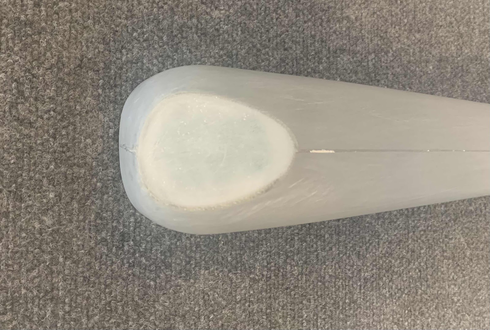
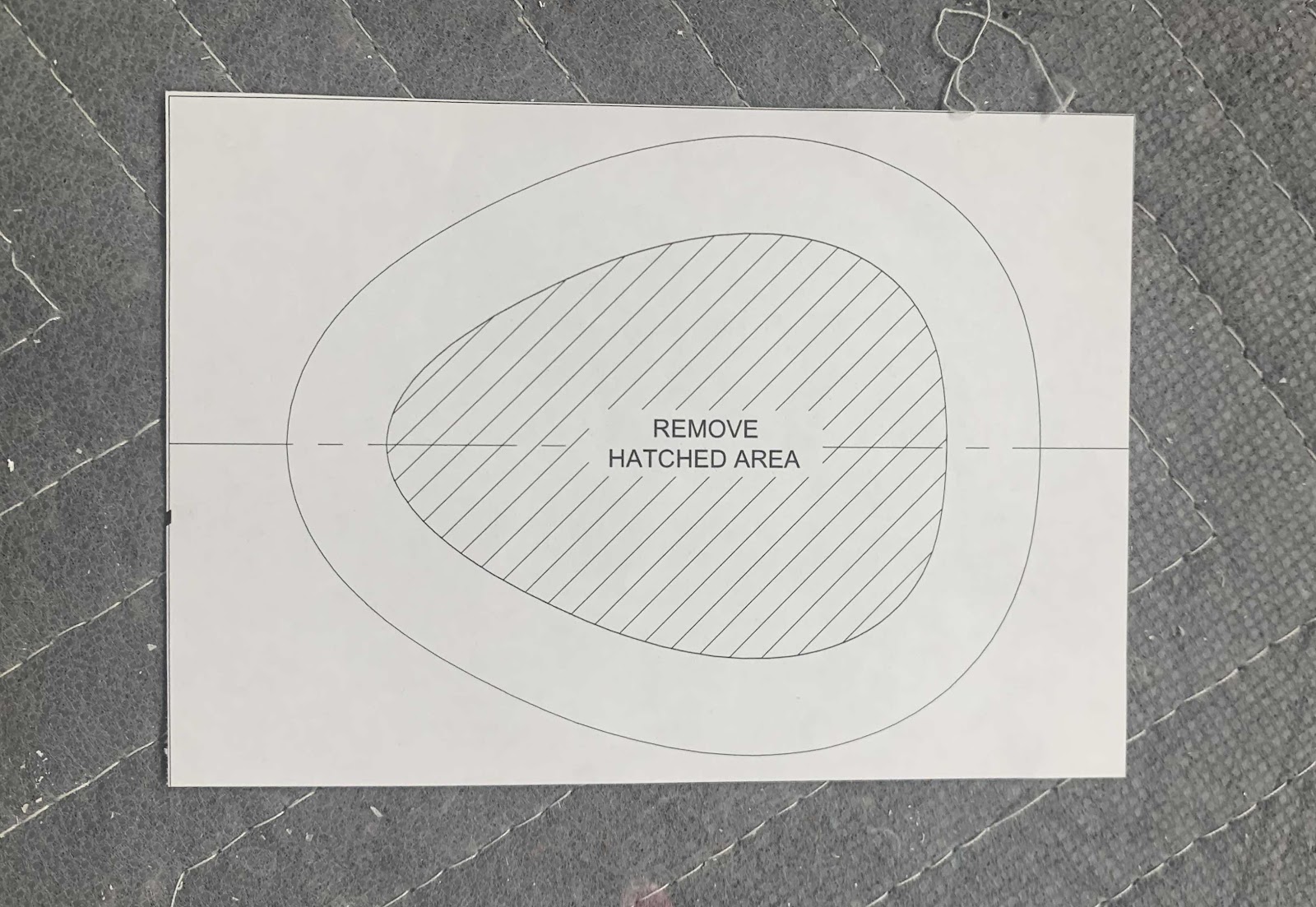
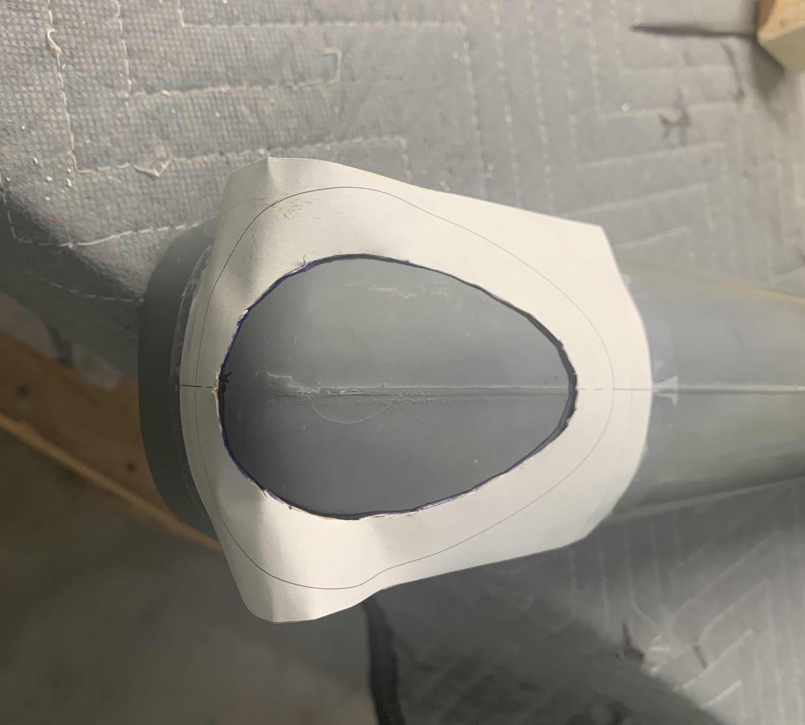
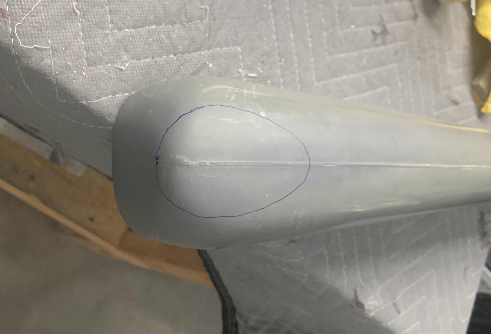
We layed up two layers of fiberglass sheet and let it cure over night.  The next day, we trimmed the cured fiberglass to a size just a little wider and LONGER (important) than the Vertical Stabilizer Tip (as shown in the picture below).....and traced the actual size of the Tip onto the fiberglass.

With the fiberglass patch trimmed and in place under the Tip, I used a popsicle stick to apply the flox mixture to the inside of the Tip where it meets the fiberglass patch.

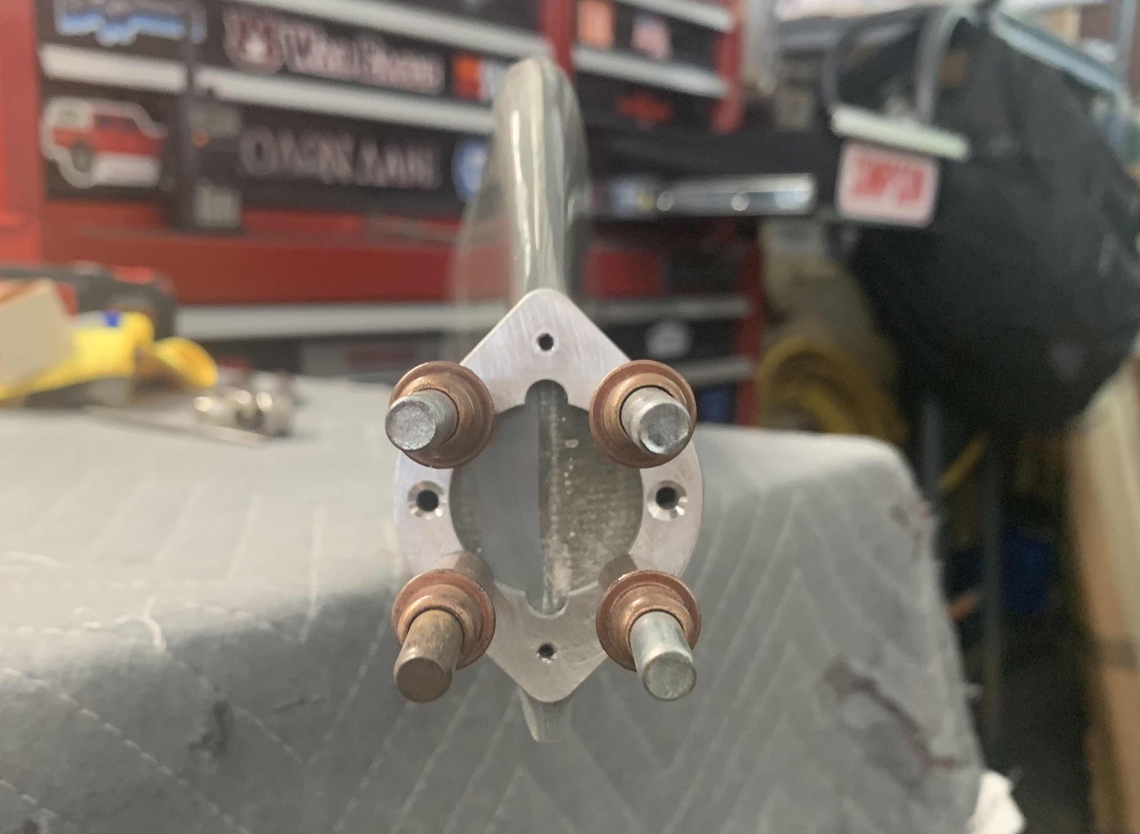
The Tip had a little bit of “inward spring” to it, so I installed this little block of wood to keep the sides of the Tip in the correct place.  
*****Make sure the wood block is not touching the flox or it will be “glued” to it.....almost happened to me!!

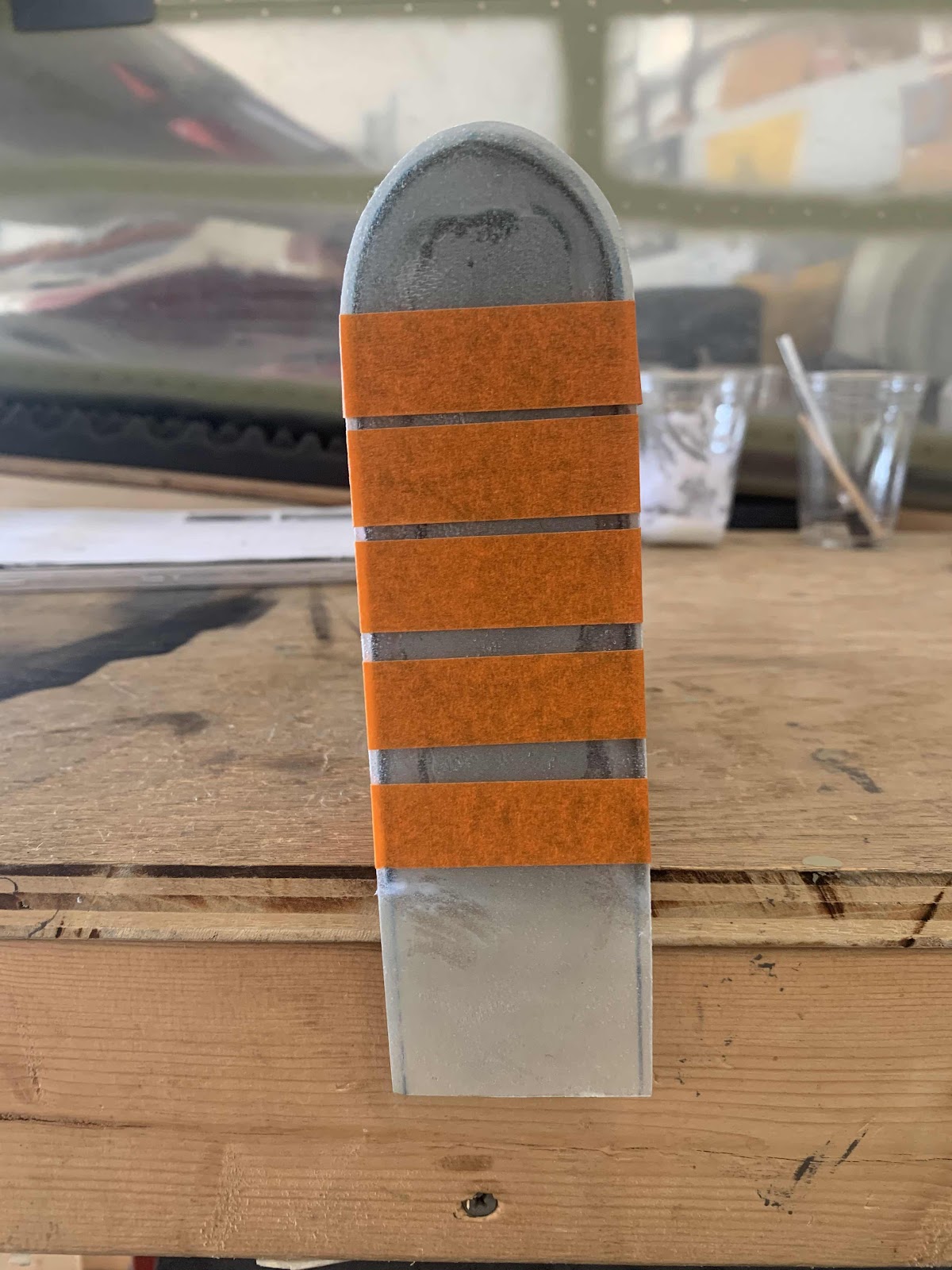
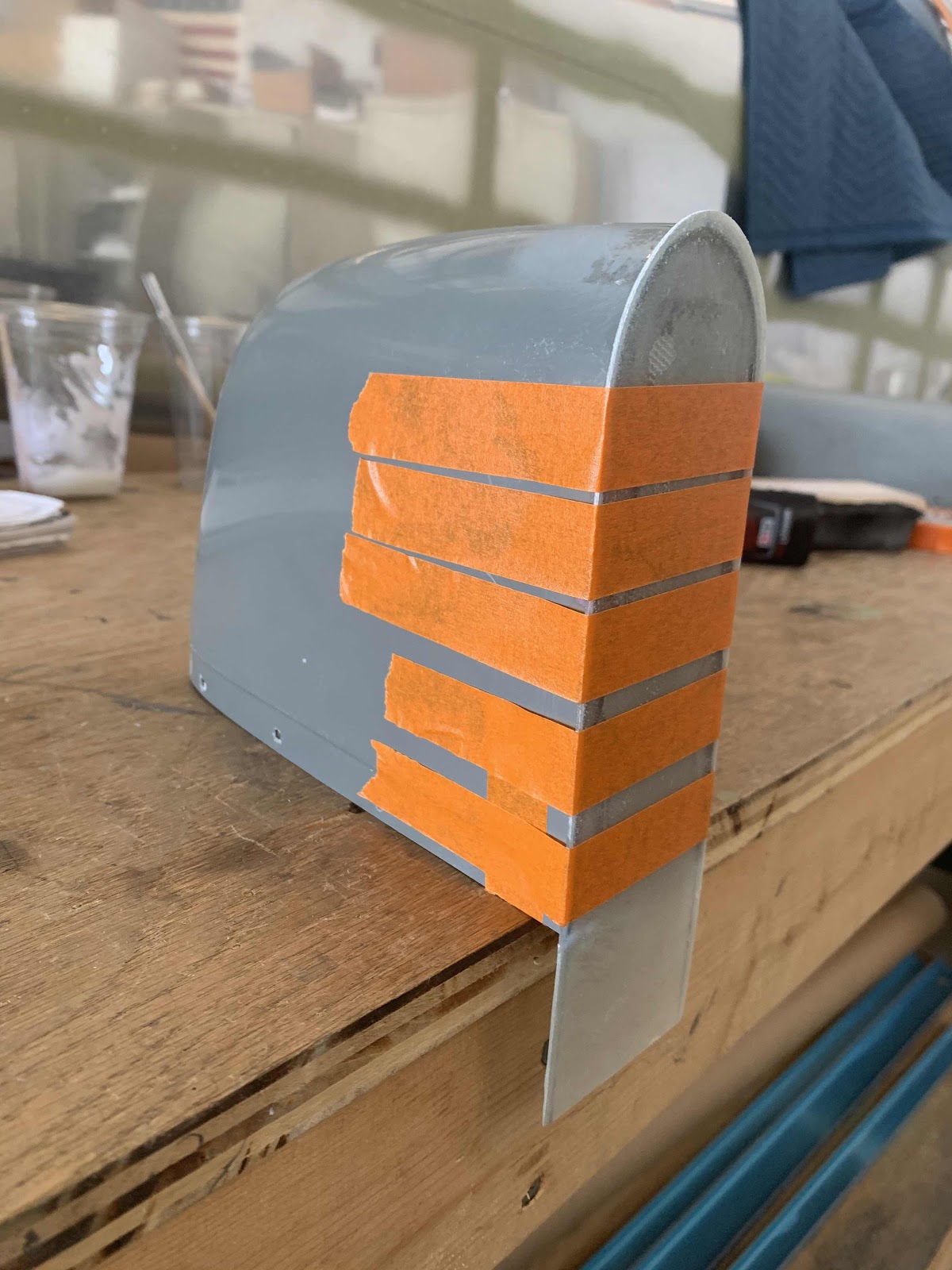
Then, we applied a bunch of orange tape to hold the two pieces together and allow the flox to cure overnight.

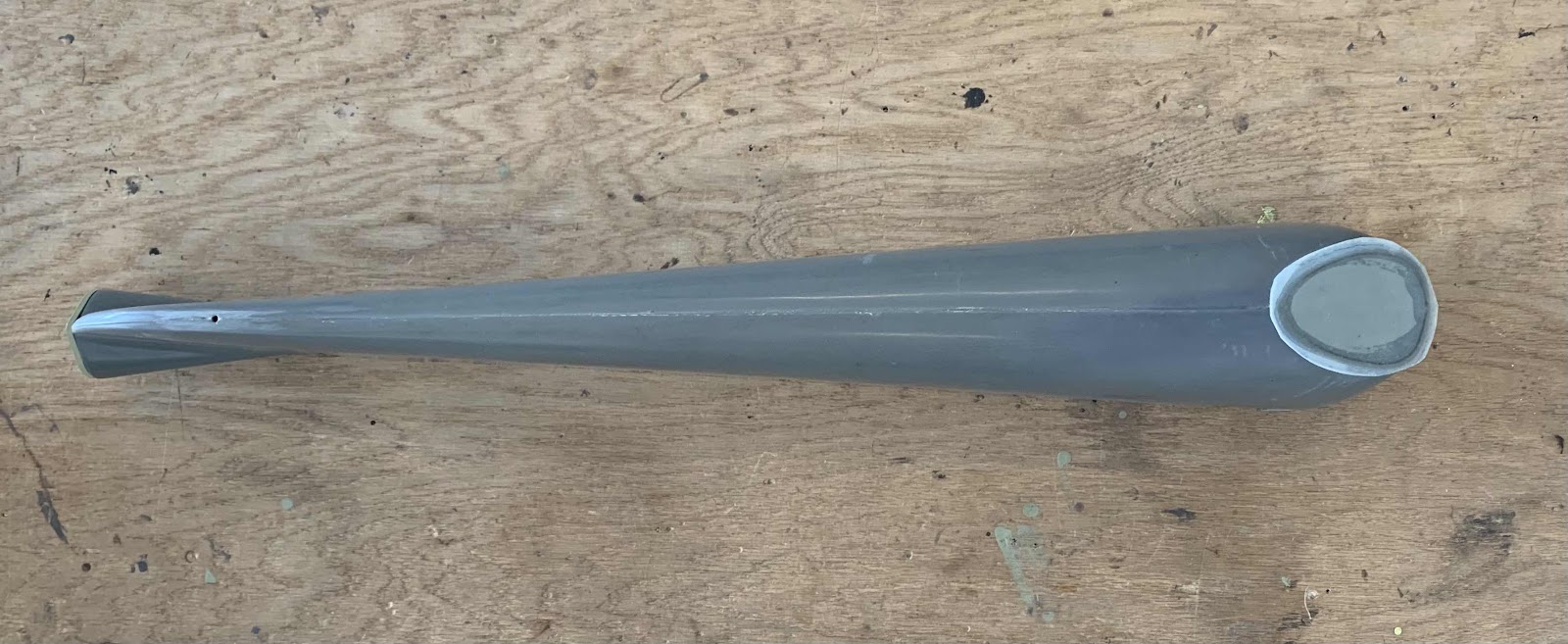
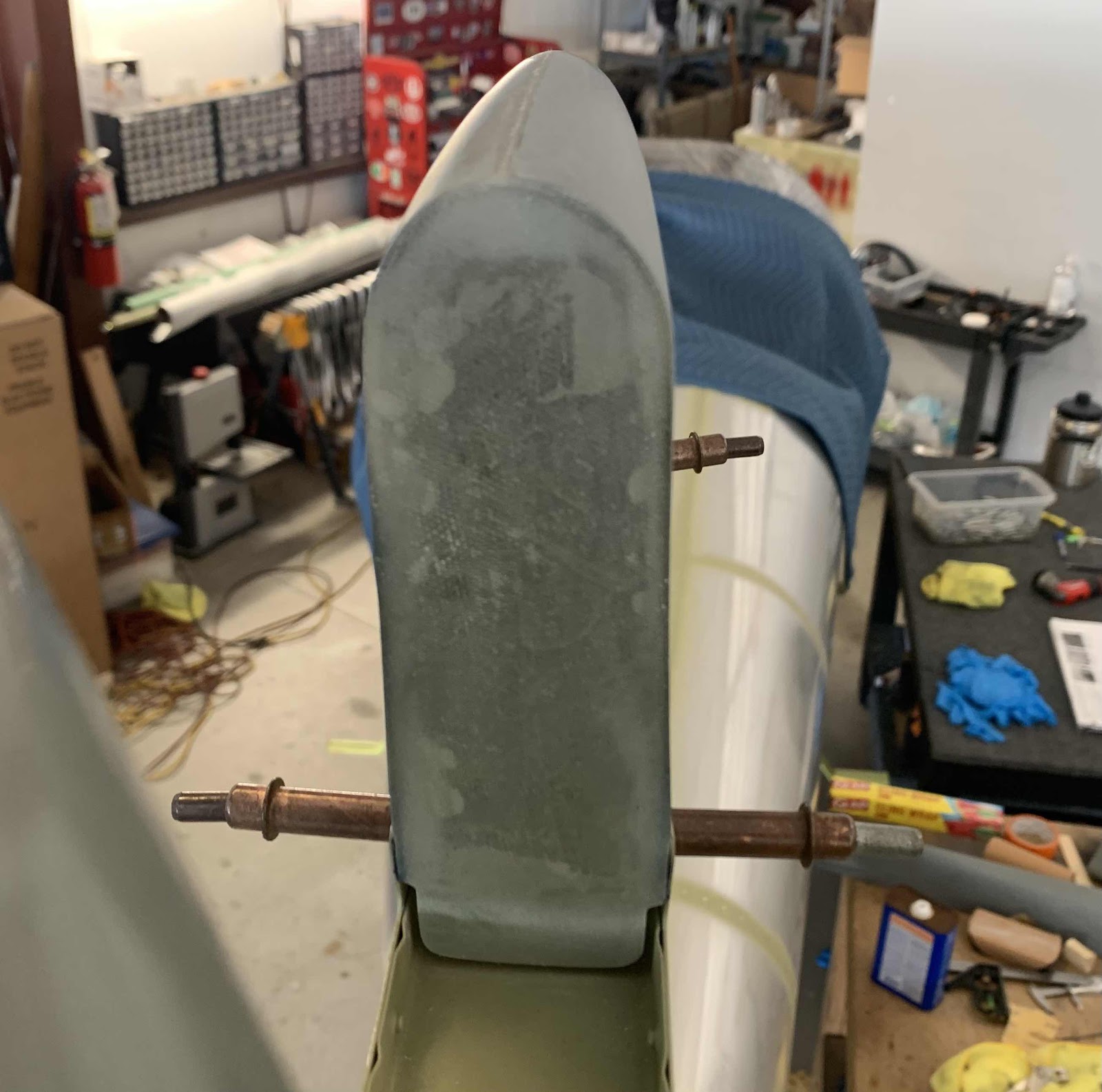
Here are a couple of different angles.  From this angle, you can see the patch is just slightly wider then the actual Tip.


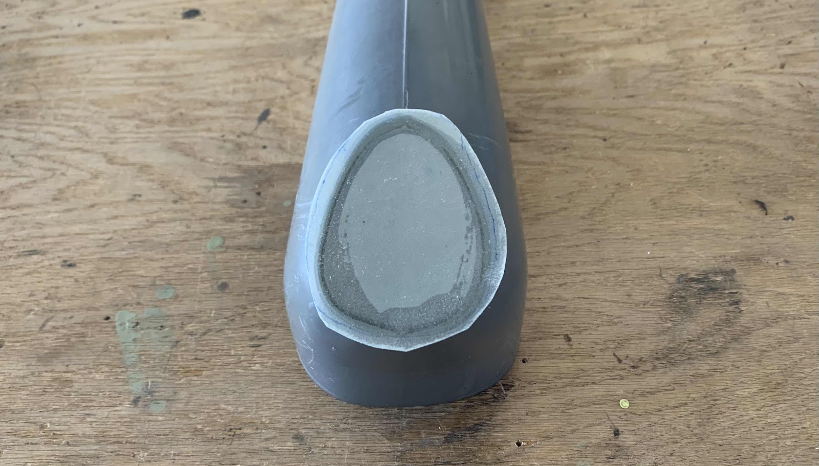
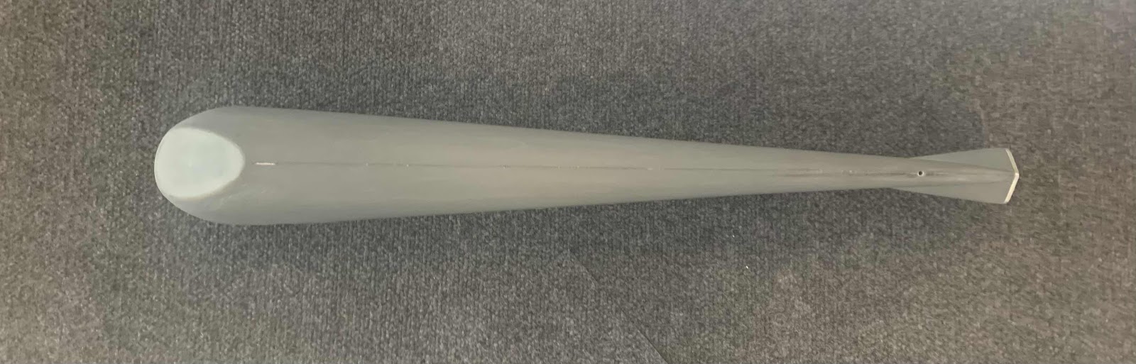
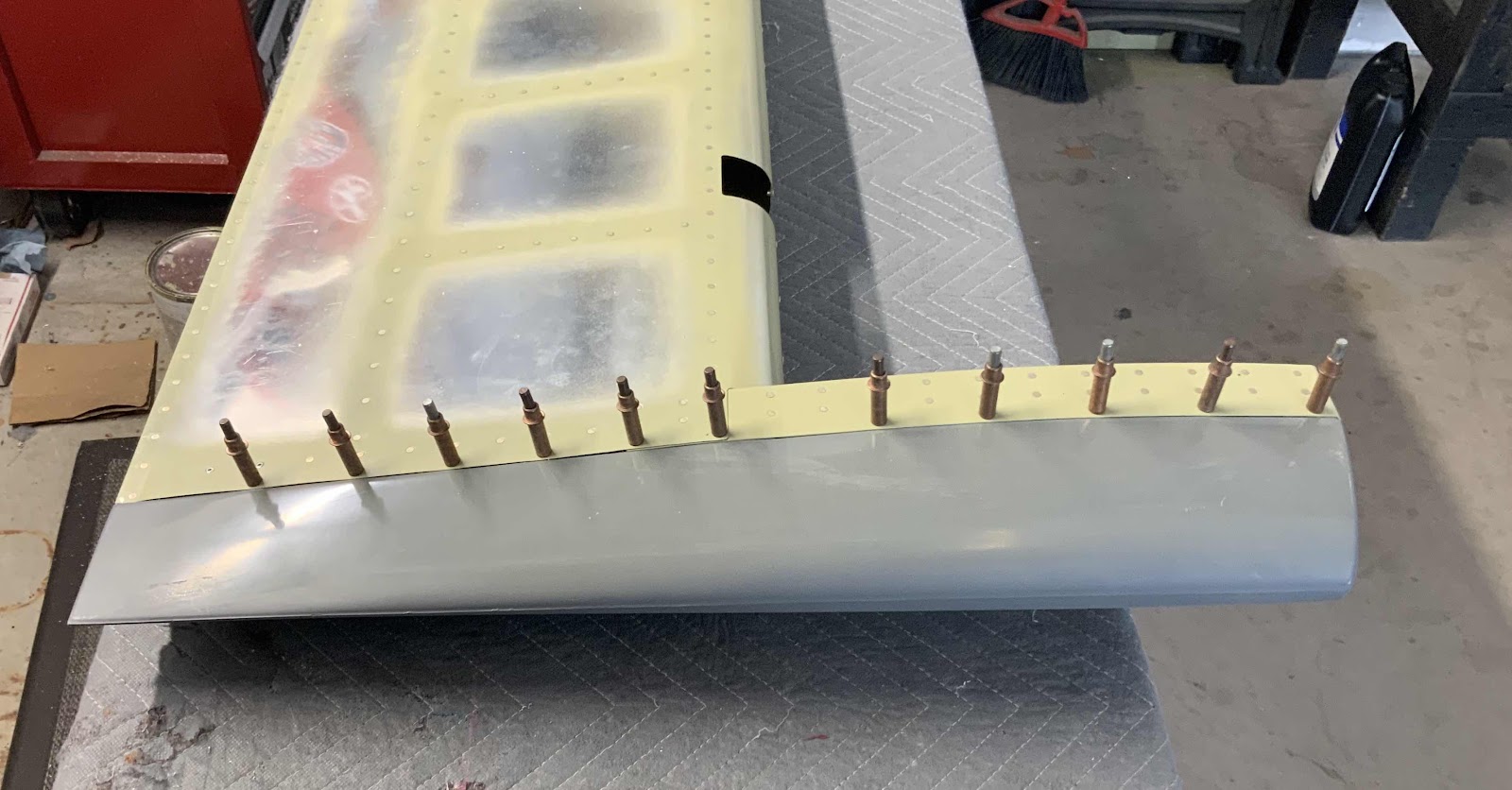
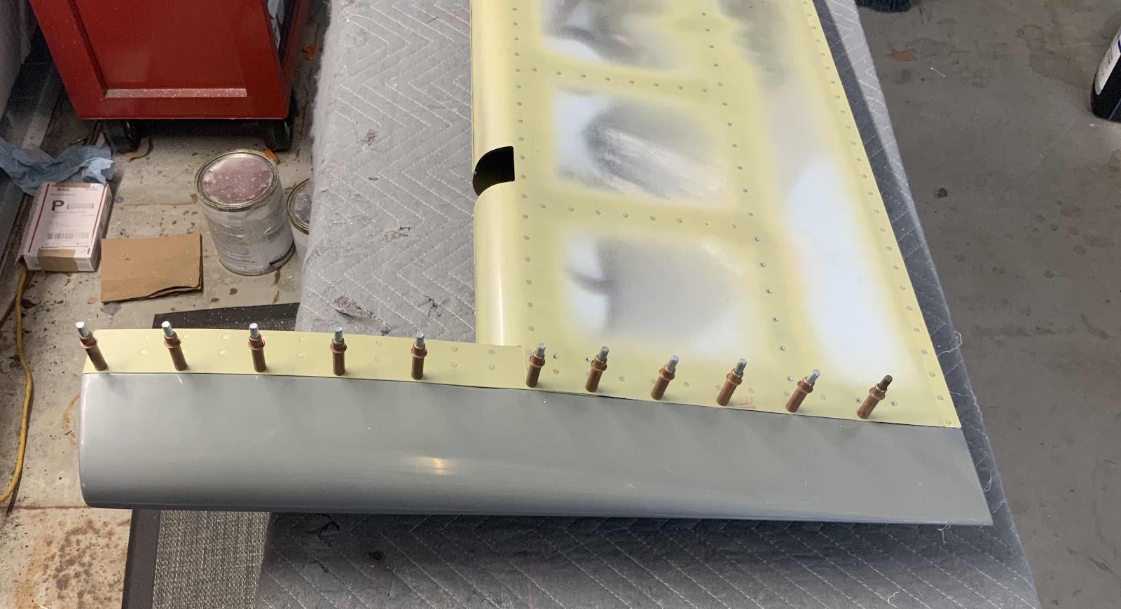
After the flox mixture cured overnight, we removed the tape.  This picture shows some work already completed on the bottom of the fiberglass patch.  The bottom side of the Tip was sanded to fit into the upper portion of the Vertical Stabilizer.  The next few pictures will show the finished product after several “fitting” installations were done.


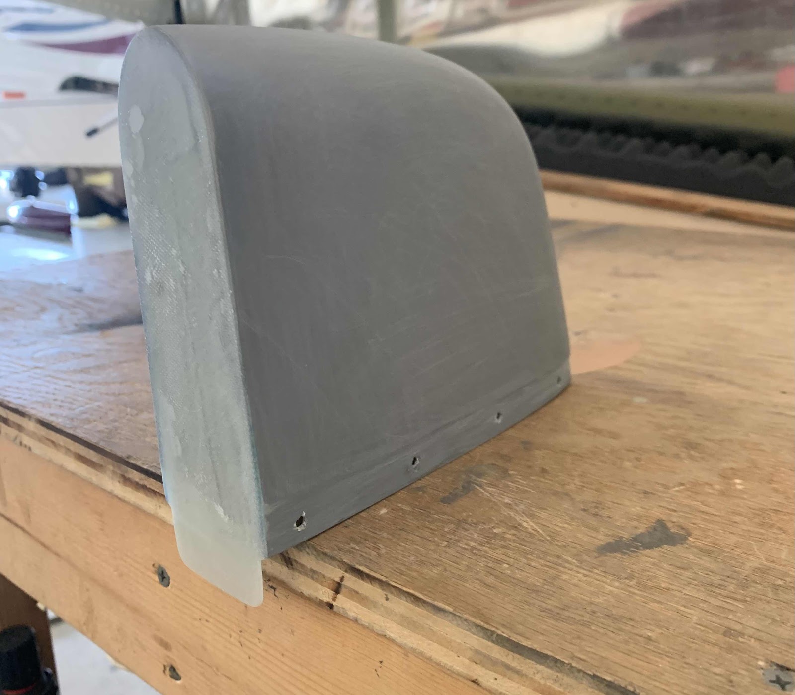
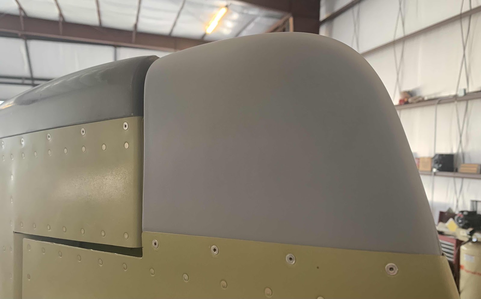
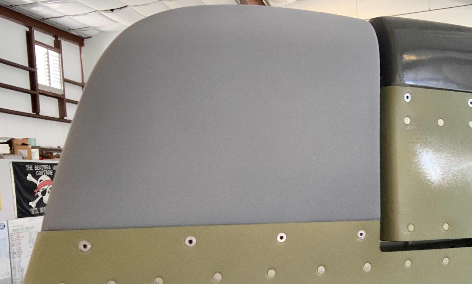
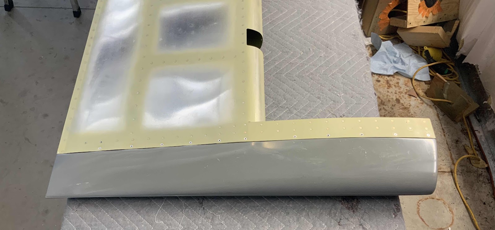
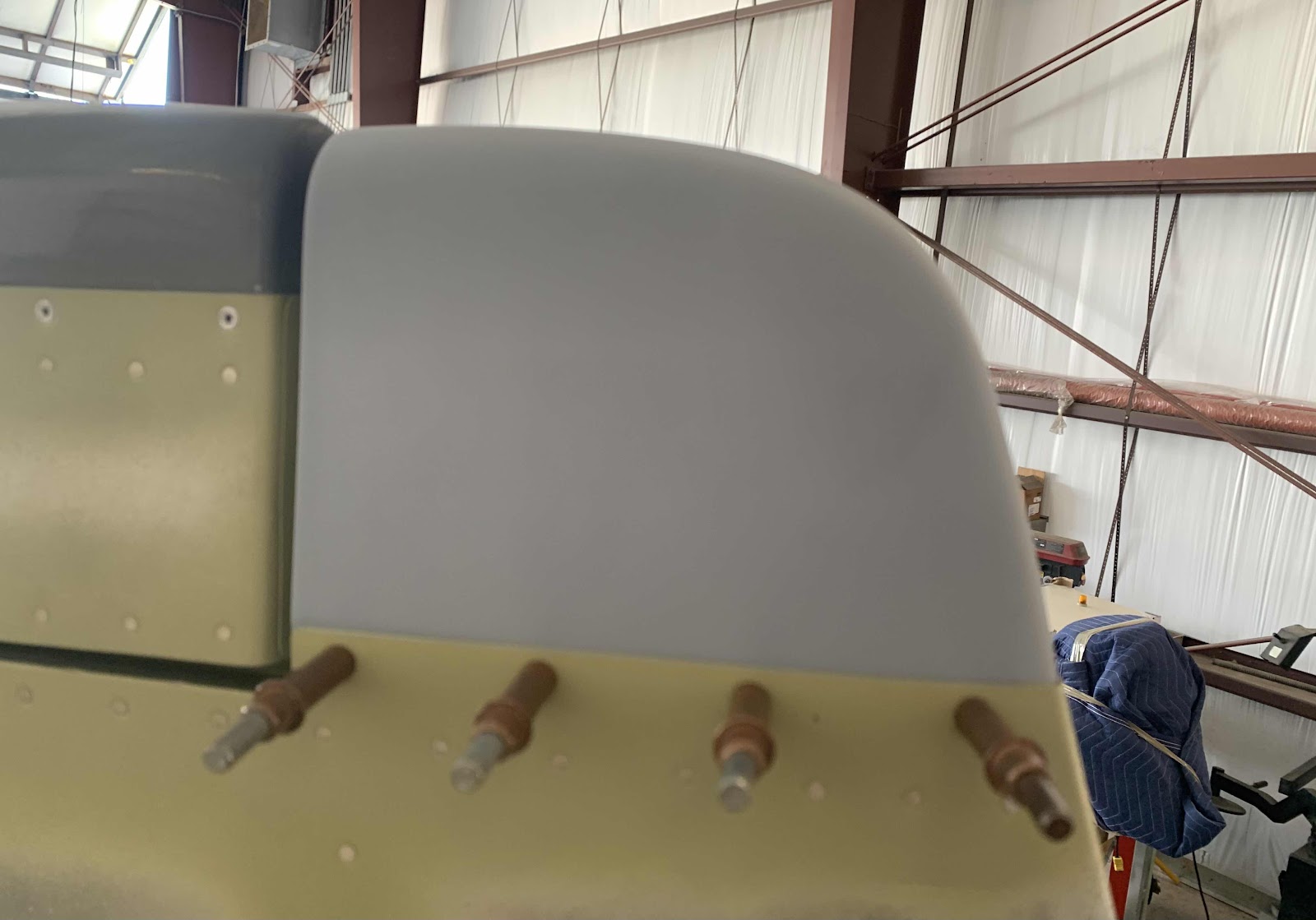
Here is the final shape of the Vertical Stabilizer Tip installed on the Vertical Stabilizer.  From this angle, you can see the completed “fitting” on the bottom of the patch.

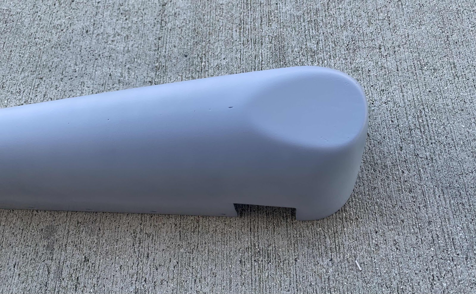
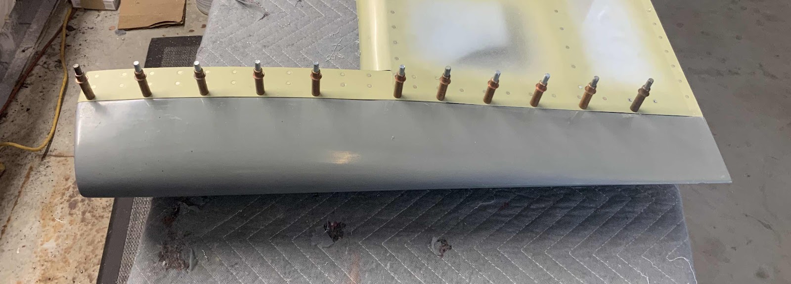
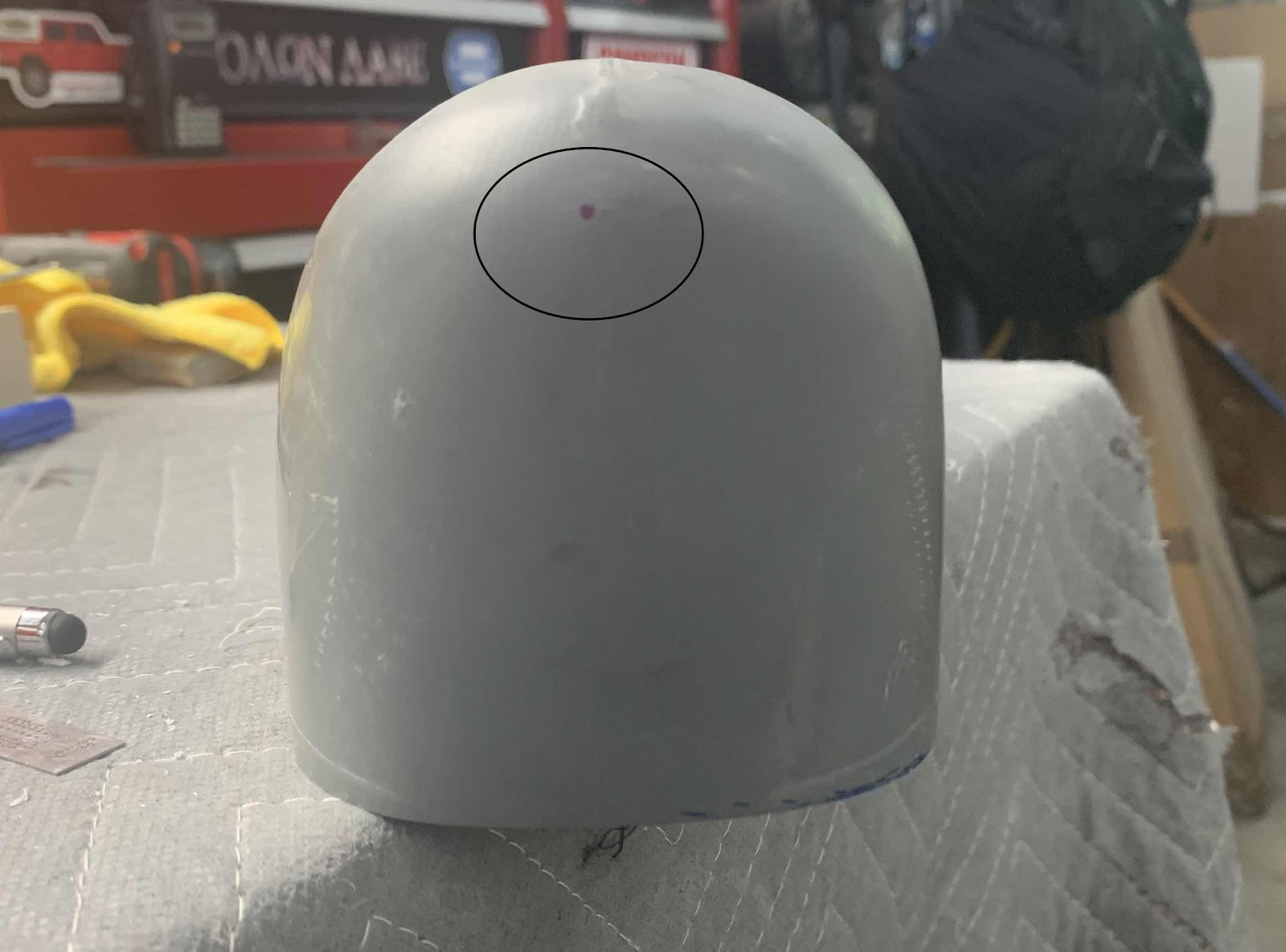
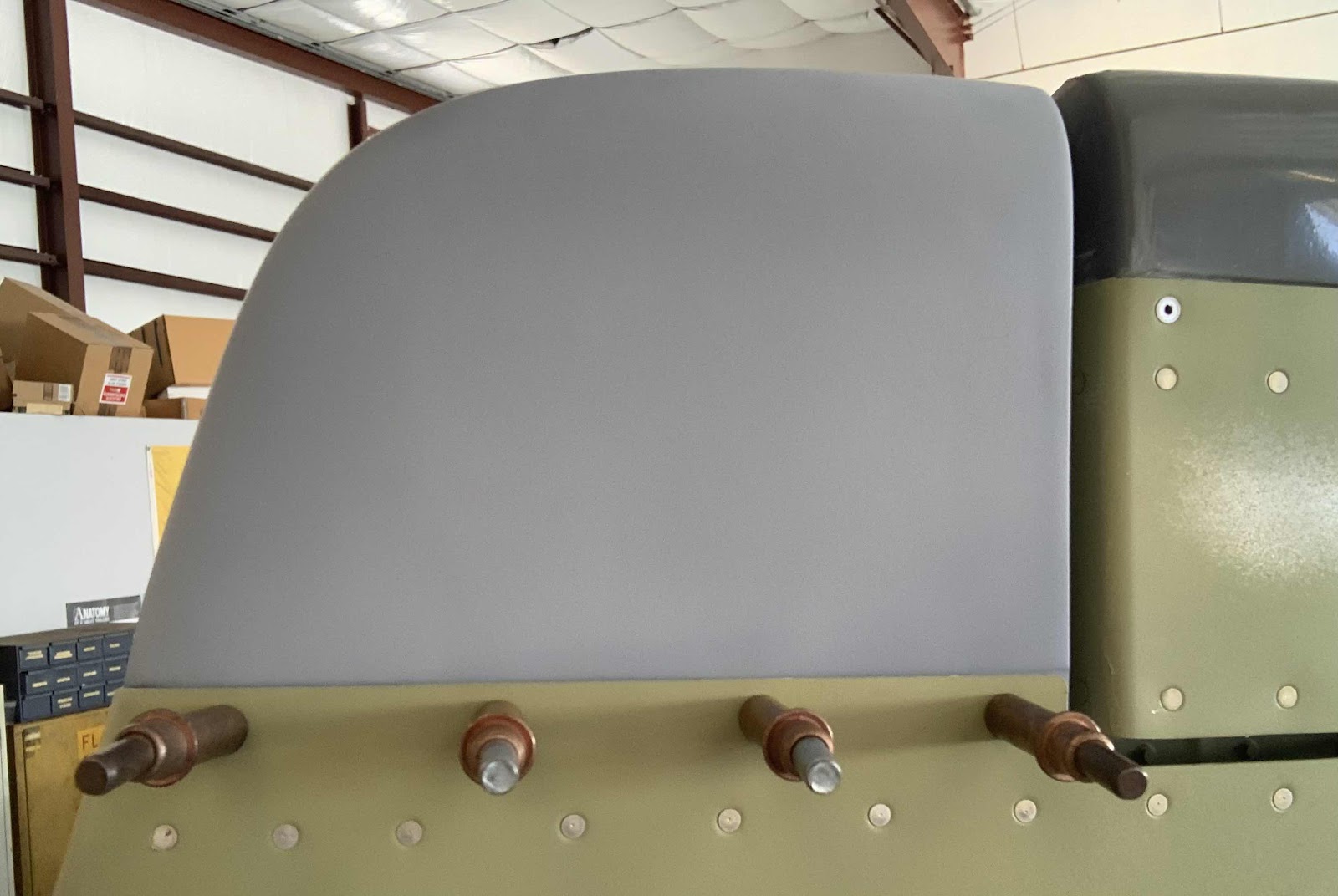
With the patch’s shape completed, we removed the Tip and sprayed several coats of filler primer on it (sanding the entire piece smooth between each application of primer).  This picture shows some pin holes in the patch after a couple coats of primer.

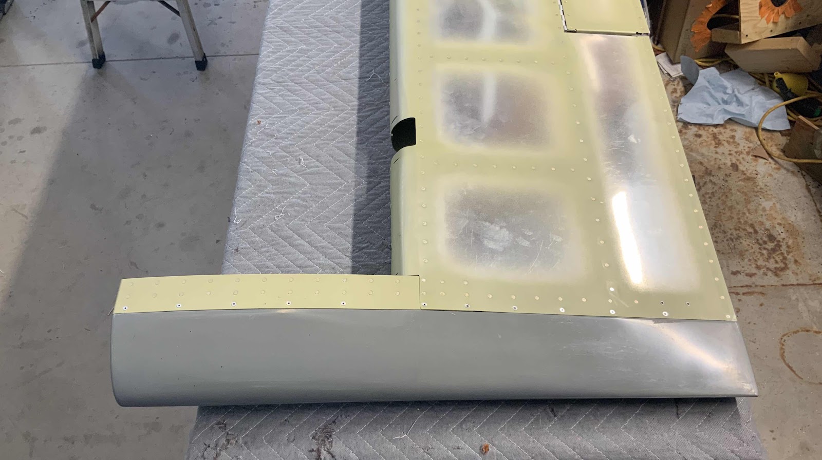
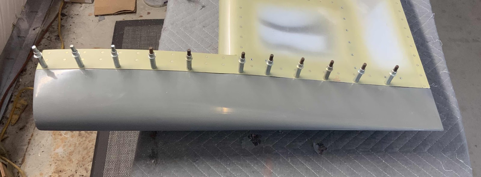
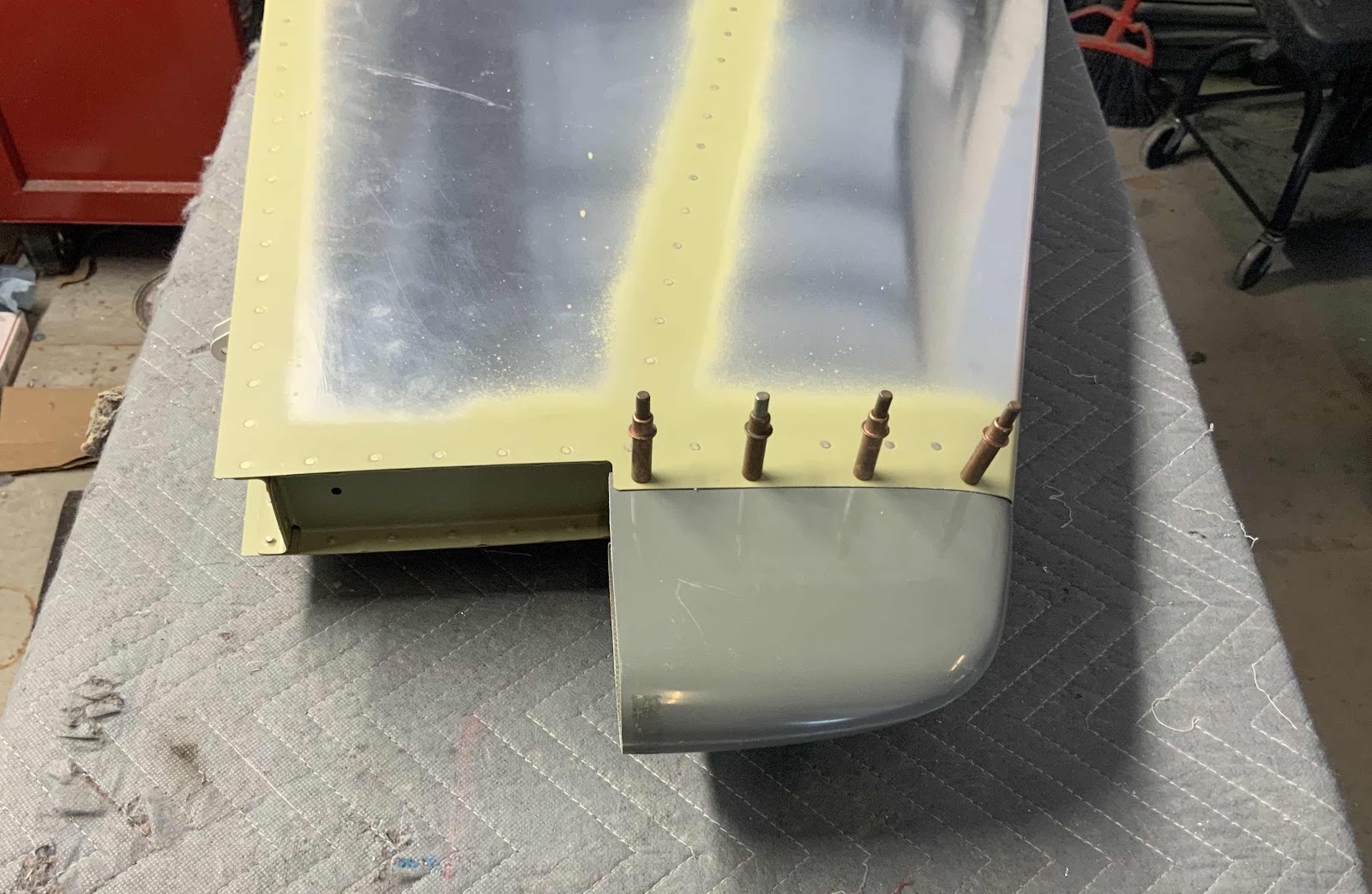
We fixed all the “imperfections” in the Tip and installed it on top of the Vertical Stabilizer for one last fitting.....


.....and here is the final installation of the Tip using the eight CS4-4 rivets.


Saturday, April 3, 2021

Empennage, Fairings (Part 9, 10, 11)

The work covered in this entry was completed over the course of three works sessions between March 20 - 26, 2021.

In Part 4, we had to modify the R-912 Bottom Rudder Fairing in order for it to clear the tail spring (tail wheel aircraft only).  After we cut a huge hole in the bottom of the Fairing, it now needs a patch.  So, we coated a piece of scrap aluminum with candle wax, layed up two layers of fiberglass fabric and waited overnight for it cure.

After the patch cured, it was trimmed just slightly bigger than the hole in the Bottom Rudder Fairing.....as shown in the next pictures.  The edges of the hole in the Fairing were coated with a small amount of epoxy resin, the patch was placed in position over the hole and I put a heavy bucking bar on top of the patch to hold it in place (to allow the epoxy to cure).  This will allow the two pieces to be bonded together.

In this picture, you can see the “ring” created between the patch and the Fairing where the epoxy was applied and has cured.

After the parts were bonded together, I flipped the Fairing over and used a popsicle stick to apply a filet of flox mixture to the inside where the patch and Fairing met each other.....

.....and then placed a precut piece of fiberglass cloth over the patch.  The fiberglass cloth was saturated with epoxy resin and put into place as shown in the picture below.  (You have to look closely, but you can see the fiberglass cloth.....just slightly larger than the patch).

After everything was bonded and cured, we started sanding to get the final shape of the patch on the Fairing.  The next two pictures show the initial sanding of the Fairing.


After applying several coats of primer filler, here is the finished product.


Not to bad considering this was my FIRST attempt at using fiberglass.....I’ll take it.

Tuesday, February 16, 2021

Empennage, Fairings (Part 8)

During this session, I fitted the Empennage Gap Covers that cover the gaps between the horizontal stablilizer and fuselage.


After I was satisfied with how they fit, I treated the covers with alumiprep, alodine and primer.

Saturday, October 3, 2020

Empennage, Fairings (Part 7)

In Part 4, I completed the work on the Tail Light Adaptor Ring on the bottom of the Rudder Fairing.  The last thing I needed to do was enlarge the center hole enough for the rear of the AEROLED Suntail to pass through the Fairing.  I used step bit and enlarged the hole one step at a time.  Ultimately, 1/2” was the size that worked.  Here is what it looks like.

In this picture, you can see the aft side of the Suntail showing what needs to clear the Fairing.

The screws aren’t installed in the Suntail, but here is what it will look like in the Fairing.

Saturday, September 12, 2020

Empennage, Fairings (Part 6)

Tonight was a relatively short session.  I only installed 42 CS4-4 rivets (22 on each Fairing); however, completed the Fairing installation on the left and right Elevators. 

This is the top of the right Elevator with the rivets installed.....

.....and the bottom of the right Elevator.

This is the top of the left Elevator with the rivets installed.....

.....and the bottom of the left Elevator.


Saturday, September 5, 2020

Empennage, Fairings (Part 5)

During today’s work session, I started work on the two E-912 Elevator Tip Fairings.  The aft section of the Fairing flanges had to be trimmed to clear the trailing Edge (just like on the Rudder).  Once that was completed, there was surprisingly little trimming required on the Fairing to achieve a very, very good fit.  In the two pictures below, the Fairings have been fit to the right Elevator and match-drilled #40 (ensuring the trailing edge of the Fairing was aligned with the trailing edge of the Elevator).


The next two pictures are same Fairings on the right Elevator with the completed next step.....final-drilling the holes to #30.


The next two pictures show the left Elevator with all the completed steps up to having the holes final-drilled to #30.


I will still need to remove both Fairings in order to dimple the Skins and countersink the Fairings for the CS4-4 rivets.  However, I will complete those steps during the next work session.


In the meantime, I started work on the VS-909 Vertical Stabilizer Tip Fairing.  I lightly sanded the very front of the Fairing to make a better fit against the Vertical Stabilizer Skin.  Once the fit was acceptable, the eight holes (four on each side) were drilled.....first match-drilled to #40 and then final-drilled to #30.  Here are both sides of the Vertical Stabilizer Tip Fairing......the left side.....

.....and the right side.

There is still some trimming work remaining on these Fairings, but I wanted to fit the Fairing to the Vertical Stabilizer before I trimmed and removed any additional material from the Fairing.  For example, if you look just to the right of the cleco on the aft side of the Fairing....there is a little bit of Fairing sticking out slightly past the Verttical Stabilizer Skin. This part of the Fairing will need to be removed at a 90 degree angle to the Vertical.  Additionally, the aft side of the Fairing will need to have a patch installed to cover the back side of the Fairing.

So, more to follow....

Friday, September 4, 2020

Empennage, Fairings (Part 4)

Today’s session will initially focus on installing the Tail Light Adaptor Ring we purchased from Cleaveland Aircraft Tool.  The tail light adaptor ring that comes with the kit would do the job just fine, but the aluminum is rather thin and I wanted something thicker/stronger.  The Adaptor Ring from Cleaveland is much more robust at 1/8” thick and works directly with the AeroLED Suntail Anti-Collision/Position/Strobe Light.  We didn’t use the installation instructions from the plans for this install because the Cleaveland Adaptor Right came with its own instructions.

To start, the aft side of the Rudder Bottom Fairing was sanded smooth to allow the Adaptor Ring to sit flush.  To get the smooth, flat finish I wanted, I used a wood block and 220 grit sandpaper.  Once it was flush, the Adaptor Ring was placed into position for proper alignment.  For the install, I initially drilled #30 the top right hole, checked the alignment again and drilled the remaining five holes.  Shown below are all six of the holes drilled #30 (four of the holes with clecos and the two holes between the clecos).  NOTE:  The two holes on the top and bottom of the Adaptor Ring will be used to attach the actual AeroLED Suntail to Ring.

Here are a couple of pictures showing the Adaptor Ring alignment to the Rudder Bottom Fairing.  At this point, I also marked the upper and lower light mounting holes on the Fairing.


Once all six of the Adaptor Ring mounting holes were drilled, the Ring was removed.  Then, the upper and lower light mounting holes (marked prior to removing the Ring) were drilled to #30.  These holes don’t actually do anything for the Suntail mount.....they just make room in the Fairing for the mounting screws to pass.  Next, the center of the Fairing was found by drawing a line between each opposing hole.....as shown with the blue lines below.  An certain amount of the Fairing will still need to be removed in the center to accept the AeroLED.  However, I didn’t have the light at the shop today to see how much.  I will do this during the next work session.

Moving on to the opposite end of the Fairing.  There is a note in the plans that says, “It is necessary to modify the R-912 Bottom Rudder Fairing to clear the tail spring in the tail wheel configurations”.  The next few steps are this modification.  The picture below shows the template that was located in the plans.  The template was cut out and glued to a stiffer material (packing paper) to make it a little stronger and easier to work with.

The next step was to measure and mark a location as directed by the plans.  This location is shown with the blue dot in the circle below.


The template was then taped to the Fairing.....

.....and traced onto the Fairing.  Not the smoothest trace, but I got the idea of what needs to be done.

The material within the blue traced area will need to be removed. I initially removed most of the material with the cutoff wheel.....

.....and then sanded the Fairing with 220 grit sandpaper to the appropriate location.  Still a few jagged edges, but a fiberglass patch will be used to cover the hole.