Showing posts with label Section 18-Fuel Tanks. Show all posts

Sunday, January 6, 2019

Wings, Fuel Tanks (Part 36)

In the last session, I taped off the Right Fuel Tank for Akzo Priming.  Guess what I did today?

Here is the Aft Baffle after priming and removing the tape.....

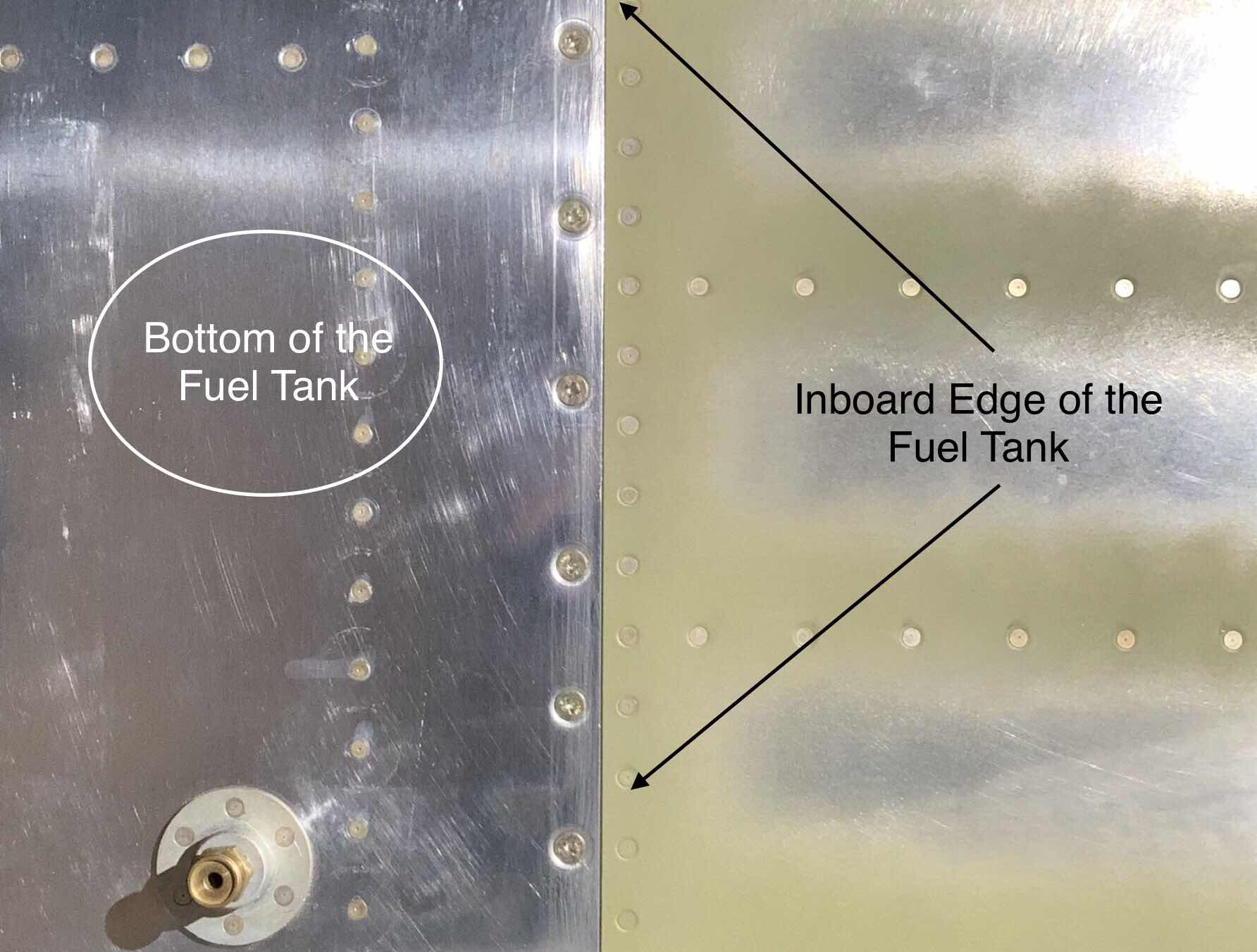
.....the Inboard side of the Tank.....

.....and the Outboard side of the Tank.

Here is the hardware that will be used to hold the Fuel Tank onto the Wing.  The hardware consists of 21 bolts (three AN3-5A and 18 AN3-4A) and 77 AN509-8R8 screws.


After allowing the primer to dry on the outside of the Fuel Tank, it was time to install it on the Wing.  The first step was to install the bolts through the Main Spar into the Fuel Tank Attach Zees as shown in the plans excerpt below.  (Part 34 shows some close ups of the installed bolts for the Left Fuel Tank).

To install the screws, I used the same method to install the Right Tank as I did for the Left Tank.  I took each screw hole.....

.....used a paint brush to brush on some of the primer.....

.....installed the screw wet.....

.....and used a rag with MEK on it to wipe away the excess.

After installing the 21 bolts and 77 screws, the Right Fuel Tank is finally installed on the Right Wing.

A view of the Outboard side of the Fuel Tank with Filler Cap.

And back to bed in the wing cradle to wait for the next step.

Section Complete

Saturday, January 5, 2019

Wings, Fuel Tanks (Part 35)

Prior to Akzo priming the outside of the Left Fuel Tank, I wanted to test fit the Tank to the Wing in case it need to be sanding.  Shown below is the Fuel Tank temporarily attached to the Left Wing.  The fit was perfect....almost!

The only area on the Left Fuel Tank needing a slight “adjustment” is located in the white circle in the picture below.  This is the area where the Fuel Tank Skin and the Inboard/Outboard Bottom Wing Skins meet.  This area had to be slightly sanded in order to sit flush against the Main Wing Spar and NOT on top of the Bottom Skins.

Once I completed the final test fit, it’s now time to Akzo prime the outside of the tank.  The four pictures below show the Tank taped off and ready to be primed.

Rear Baffle and Tank Attach Zees.....

.....Inboard side.....

.....Outboard side.....

.....and the Top Skin.

Thursday, January 3, 2019

Wings, Fuel Tanks (Part 34)

The work during this session was completed on Wednesday, January 2, 2019

The picture below shows the black Proseal I applied to Aft Baffle seams and Tank Attach Zees.  I’ve said it before, this might be complete overkill, but I do not want the tank to leak.


After allowing the Proseal to dry over some of the Christmas Holiday, it’s now time to leak check another portion of the Right Fuel Tank.  In Part 35, Jeff and I installed the Aft Baffle on the Right Fuel Tank (which is the focus of this leak check).  As with the Left Tank, all leak checks will be completed with actual 100LL Avgas....after all, isn’t that what’s going in it??  So, I filled the Fuel Tank with 5 gallons (which is enough to cover the Aft Baffle seams and a few Skin rivets not previous leak checked).  After the fuel was put in the Tank, I turned it “vertically” on the table.  In the picture below, you can see the Tank Attach Zee’s resting on the pieces of 2 x 6’s.  


Here is what it looks like “vertically” on the workbench.  I used a strap over one of the Wing Ribs to “loosely” hold the tank on the workbench in case it was bumped.  I also put cardboard down on the workbench to make it easier to spot any potential fuel leaks.

Here is the opposite side of the Tank.  The fuel level inside the tank is roughly 1/4 the way up the fuel cap on the lower right side of the Fuel Tank.  

And lastly, here is the inboard side of the Fuel Tank.  I temporarily installed the orange hose onto the tank’s air vent to vent the tank while it was sitting on the workbench being leak checked.

This is the final leak check that needs to be completed on the Right Fuel Tank.  If all checks out, the next step is to Akzo Prime the outside of the Tank prior to installing it on the Right Wing.

Friday, December 14, 2018

Wings, Fuel Tanks (Part 33)

Well, after a couple of months, Jeff and I were able to continue the work on the Right Fuel Tank.  During this session, we installed the seven T-1012 Tank Attach Zees and the T-00002 Tank Baffle.  As the instructions described, we applied a bead of Proseal on the Fuel Tank Skin from the Tank Baffle rivet holes forward.  By doing this, the Tank Baffle will  act as a “squeegee” and push the Proseal forward when installed.  Additionally, Proseal was applied to the aft flanges of the seven Tank Ribs.

Next, we installed clecos in EVERY hole that will be receiving a rivet.  Once the clecos were installed, we started riveting the Tank Baffle to Tank Ribs (starting from the center Tank Attach Zee, then working outward in both directions) and finished with the Tank Baffle to Tank Skin rivets (also starting in the center and working outward in both directions).  As with the Left Fuel Tank, the Right Fuel Tank will be receiving a combination of AN470AD4-4 and AN470AD4-5 solid rivets and AD-41H and AD-42H blind rivets in the locations indicated in the plans excerpt below.


Here is a aft section of the Right Fuel Tank after all the rivets have been installed.  In this view, you can see the seven Tank Attach Zees and their corresponding rivets.  For this installation, the closed end of the AD-41H and AD-42H blind rivets were “twirled” in Proseal prior to installation.  Additionally, you can see some of the black Proseal where the Tank Baffle and Tank Skin meet.

Here is a closer picture showing the solid AN470AD4-5 and 4-5 rivets installed on the Inboard Tank Attach Zee.  You can also see the area where the Tank Baffle and Tank Skin meet.

This is the Outboard Tank Attach Zee and corresponding area.

Kind of a cool shot down the length of the Tank Baffle showing all seven Tank Attach Zees. 

I’m not completely finished with the Tank Baffle and Tank Attach Zees just yet.  I will need to clean up several areas and apply additional Proseal to the areas where the rivets were installed and the seams around the parts.  I’m sure my personal “requirements” for Proseal application will be a bit overboard, but I DO NOT WANT THE TANK TO LEAK!!

Wednesday, December 5, 2018

Wings, Fuel Tanks (Part 32)

After completing all of the Left Fuel Tank fitting during the last session, today I installed the Fuel Tank for the final time.  Each Fuel Tank is held on to the Wing/Spar by 18 AN3-4A bolts, 3 AN3-5A bolts, and ‘77 AN509-8R8 screws as shown in the plans excerpt below.


Here is the actual bolts that will be used for the installation.  The three AN3-5A bolts are on the far right....the rest are the AN3-4A bolts.  I installed these bolts through the Spar FIRST, and then installed the screws.  Might not make that much of a difference, but I think the bolts would “pull” the tank flush against the Wing Spar.  For corrosion resistance purposes, I previously primed the Wing Spar during Section 13.  As a result, there is already a “layer” of primer between the Wing Spar and the bolt washer.

Pictured below are the three AN-3-5A bolts attaching the Fuel Tank on the inboard side of the Wing.

Here are a few examples of the AN3-4A bolt locations taken from the Access Panel locations on bottom of the Left Wing.  At the top of each of the pictures, you can also see the installed AN509-8R8 screws and nutplates that attach the Fuel Tank to the Main Wing Spar.  


Since the screws being installed are steel and the skin is aluminum.....corrosion because of the dissimilar metals. To add some level of corrosion protection, I will use a paint brush to brush Akzo Primer on the screw holes and install the screws “wet”.


Here is the primer brushed on.....


.....and a screw being installed.  After the screw was properly set, I used a rag with MEK to remove the excess primer (screw on the left).  This will all get painted over later when the whole airplane is painted, but putting some primer between he screw and skin made me feel better.

After all of the screws had been installed, the Left Wing was put back in the wing cradle until the next step.


Tuesday, December 4, 2018

Wings, Fuel Tanks (Part 31)

Today’s session focused on fitting the Fuel Tank to the Left Wing and making any necessary modifications (filing, sanding, etc) prior to final installation.  The “top skin” of the Fuel Tank fit perfectly to the Spar and Outboard Leading Edge and required no modifications for the desired fit.

However, the “bottom skin” required some sanding for the fit I was looking achieve.  I had to install and remove, install and remove the Fuel Tank several times until I was happy with the fit.  The effort resulted in very good results.  The screws installed in the pictures below are temporary and are used solely to check the fit of the Fuel Tank.  The plans state:

“The edges of the T-00001 Fuel Tank Skin must have a zero to 1/64 [0.4 mm] gap between the adjacent wing skin edges.  A larger gap may be desirable if the aircraft is to be painted, while a zero gap may be desirable if the aircraft is to be left in natural aluminum”

I definitely plan on painting the airplane, so......

The picture below shows where the inboard section of the Fuel Tank joins the Left Wing.  This area had to be sanded to achieve the fit described above.

This is the middle, aft section of the Fuel Tank where it joins to the Main Spar.  This area also had to be modified.....

Lastly, here is the inboard section of the Fuel Tank....just forward of the wing walk area (on the top of the wing).  Again, this section also had to be modified for the desired fit.


Monday, December 3, 2018

Wings, Fuel Tanks (Part 30)


After completing the rivet installation in the last session, today I started the initial fit of the Left Fuel Tank to the Left Wing.  I didn’t make any huge strides today, but did get the visual of how the Fuel Tank attaches and what need to be done prior to installing the tank.  Specifically, some areas that will need to be modified (sanded) prior to final installation. 

The three pictures below show the Fuel Tank temporarily attached to the Left Wing.  Like I said, this is temporary and provides me with the visual I need for the final installation.

Outboard section of the Fuel Tank that joins the Outboard Leading Edge.....

.....aft section of the Fuel Tank that joins the Left Wing Main Spar....

.....and finally just an overview of the Fuel Tank attached to the Left Wing.


Thursday, October 4, 2018

Wings, Fuel Tanks (Part 29)

The Left Fuel Tank has been sitting for roughly three days.  During this time, I’ve continuously checked for leaks along all the seams.  And.....

NO LEAKS!  Victory!

The Left Fuel Tank is now ready to be installed on the Left Wing.

Monday, October 1, 2018

Wings, Fuel Tanks (Part 28)

During the last session, I applied Proseal to the seams on the Aft Tank Baffle and Zee Attach Brackets.  After several days of letting it cure, now I want to leak check it with avgas.  I put a 2x6 piece of wood on the workbench and stood the Left Fuel Tank up vertically on the Zee Attach Brackets.  This set up is high enough to clear the Skins from the workbench and stable enough to not fall over.

I added enough fuel to only cover the rivets that were not previously leak checked.  I only needed about an inch of or so of fuel, so it didn’t take much.  Here are a couple of pictures looking into the Left Fuel Tank filler hole at the avgas inside the tank.


Now I need to let the Left Tank sit and see if there are any leaks.

Saturday, September 29, 2018

Wings, Fuel Tanks (Part 27)

I’ve waited a few days for the Proseal to completely dry on the Right Fuel Tank from the last session.  Now that it has dried, I will leak checked the Ribs portion of the tank with some Avgas.  In the picture below, I have added fuel to just below the last rivet on the aft side of the Tank Ribs (just below the Vent Line on the right side).  Now, I will wait a few days to make sure there are no leaks.


While the Right Tank is sitting, I moved back to the Left Fuel Tank.  The rear Tank Baffle and Zee Brackets were riveted into place during a previous session.  I want to put Proseal on the outside of the rear Tank Baffle and Zee Brackets.  Initially, I brushed adhesion promoter on the dried Proseal from the initial install of the Baffle and Zee Brackets.  After waiting the required 30 minutes, I mixed up some Proseal and brushed it along all the seams and rivet lines.  The Proseal I added is shown below in black.  Now, I’ll wait a few days for the Proseal to dry. 

Tuesday, September 18, 2018

Wings, Fuel Tanks (Part 26)

Jeff and I continued work on the Right Fuel Tank during this session.  Tonight, we riveted and prosealed the T-00003 Tank J-Stiffener, T-1003B-R Tank Inboard Rib-AFT, and T-00006 Tank Attach Bracket Subassembly.  In the picture below, the Rib and Tank Attach Bracket clecoed into place on the Right Tank.

And here is the same picture after setting the rivets and Proseal.  Additionally, on the inside edges of the Tank Skin, you can see several of the K-1100-08D nutplates after installation.

Lastly, this is the view looking down into the Right Tank on the inboard side.  Several things are visible from this view:

—The Fuel Tank Vent Line in the Upper portion connected to the Inboard Rib-AFT with the blue nut
—The inboard portion of the J-Stiffener (under the Vent Line) riveted and prosealed
—The Tank Attach Bracket on inside of the Fuel Tank riveted and prosealed

I will need to clean up some of the Proseal “mess”, but first I will let the Proseal dry for a few days.  Once the Proseal dries, I will leak check it in the same way I did the Left Wing.....by adding 24 gallons of avgas.