This blog was created to memorialize the building process of my Van's Aircraft RV-14 and to satisfy the requirements for certification in the Experimental Amateur Built Aircraft category. It will also serve as a central location for ME to reference in the future on processes and techniques I used during the build. Additionally, it will allow my family, friends, and other interested builders the opportunity to follow along during my build…..and might be helpful to someone along the way.
LONG, LONG day of finishing up all the countersinking on the Left and Right Main Spar. Anyway, we are finally done....thank God. I am so sick of countersinking. I’m sure there will be many, many more opportunities to countersink in the future, but I’m good with it for now.
After finishing the countersinking for the Fuel Tank Attach screw holes, the last “group” of holes to be countersunk were for the Wing Access Plates (12 nutplates in each Wing). As indicated in the excerpt below, the maximum outside diameter is .308 (7.8 mm) and maximum inside diameter is .158 (4.0 mm). We countersunk the holes to an outside diameter of .290.
Finally, both Spars are done. The next time I mix up some Akzo primer, I’ll spray the holes that were countersunk on the Spars. Until then, I put them back in the crate they came in from Van’s.
We completed the installation of all the nutplates on the Right Main Spar.....
....and installed the two Aileron Bellcrank Brackets. Just like on the Left Main Spar, the bolts that hold the brackets were already installed in the Spar Assembly from Van’s.
Now, both Spars are almost complete. We need to countersink the nutplate screw attach holes and torque the eight bolts holding on the four Aileron Bellcrank Brackets.
We will start this process by countersinking the larger Fuel Tank Attach screw holes. In Part 6, I added two excerpts from the plans defining the maximum inside and outside diameters of the coutnersink. The maximum outside diameter of the countersink is .370 (9.4 mm) and maximum inside diameter of the countersink is .220 (5.6 mm).
Here is the excerpt:
With these maximum diameters in mind, I found the middle distance of .295 (7.5 mm). I made the initial countersink (using a #30 countersink cutter in the cage as directed in the plans) to the middle figure and it looked very shallow. The Fuel Tank Skins are .032 thick, so I found a scrap piece of aluminum of the same thickness, drilled it, dimpled it with a #8 screw dimple die, and checked the fit.....it was shallow.
I was interested what other builder’s were doing, so I started looking at other builder’s websites. Shawn’ssite provides some details on how he accomplished his countersinking, as he countersunk his larger holes to a diameter of .355. Keeping the maximum of .370 in mind, I started to enlarge the diameter of the hole a little bit at a time. After each “layer” of aluminum was removed, I checked it against my scrap template and the guage below. Eventually, I settled at a hole diameter of .350. That fit pretty good with the scrap template I dimpled. Now, we started on the rest of the holes.....continuously checking the diameter.
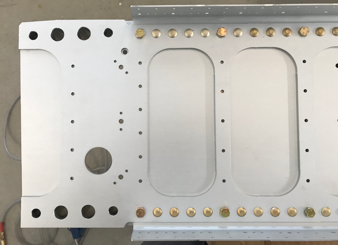
Here is the first completed Main Spar Flange with the nutplate screw holes countersunk to a diameter of .350.
Just for information: I did find my cordless drill made a “better hole” than my air drill. I have a variable speed Sioux air drill, but for some reason (probably operator error) it tended to chatter a lot and not leave a round countersink. The cordless drill cut much smoother and made a pretty round hole. If I had to, I used my deburring tool to make a few turns at the very end to make sure the hole was round. I think it worked out pretty well in the end.
Due to the depth of the coutnersink versus the thickness of the Flange, as Shawn mentioned, there is a knife edge created. Because I chose to install the nutplates BEFORE the countersinking, I’m not able to “clean up” the knife edge from the opposite side of the Flange. It’s not really all that bad, but some of the inner circles are not completely round.
Anywho, we hope to finish the countersinking in the Spars tomorrow and they will be complete. Once we are finished, I will use a small airbrush to Akzo prime the holes we countersunk in the Flanges.
We let the Akzo primer dry overnight, so now it’s time to install some nutplates.....lots of nutplates. The Left and Right Main Spars will receive 154 nutplates (77 in each Spar) via a combination of the these four nutplates:
K1000-06, 24 (12 on each Spar)
MS21-53-L08, 20 (10 on each Spar)
K1000-3, 14 (7 on each Spar)
K1100-08, 96 (48 on each Spar)
Here is what they look like.....
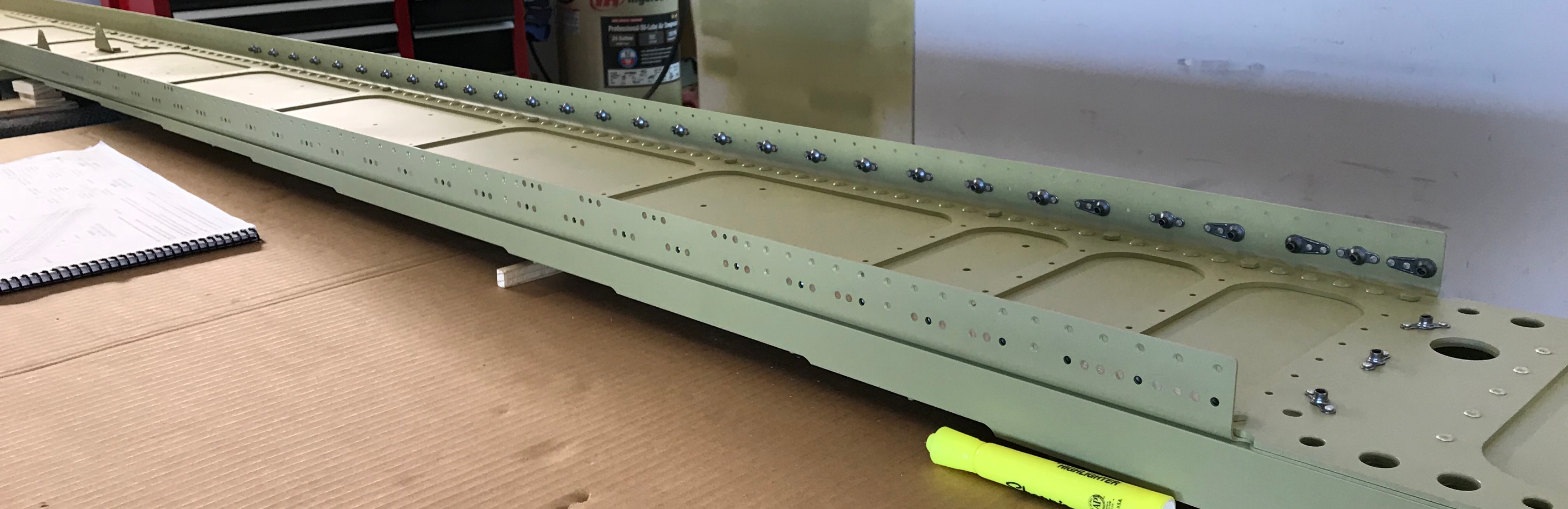
The plans call for AN426AD3-3.5 rivets to be used to attach all the nutplates to the Flanges of the Main Spars. Here you can see the nutplates attached to the Upper Flange of the Left Main Spar. We used the hand squeezer for all of the rivets on these nutplates.
These are the nutplates on the Lower Flange of the Left Main Spar. We also used the hand squeezer for all of the rivets on these nutplates.
Here is a close up of the one of the Flanges. The row of nutplates on the top will be used to attach the fuel tank. The ones on the bottom will be for the Wing Access Plate.
These are the three nutplates in the Left Main Spar web on the inboard side. We used the rivet gun and small tungsten bucking bar for these rivets because the pneumatic squeezer yoke didn’t have enough reach. However, we were able to use the pneumatic squeezer for all five of the AN470AD4-6 universal rivets on the right.
These are the four nutplates in the Left Main Spar web on the outboard side. We were able to use the hand squeezer on the two closest to the tip (on the left) and backriveted the two near the SB500-6 Snap Bushing.
Lastly, the two Aileron Bellcrank Brackets were bolted to the Spar. The bolts used were already installed in the Spar when it was shipped from Van’s, so they had to be removed and re-installed with the Brackets.
Here are a few pictures of the Left Main Spar with all nutplates attached.
The only thing left do on the Left Main Spar is the countersinking of the nutplate screw attach holes. I plan to finish the Right Main Spar (to this point) and complete the final countersinking step on both of them at the same time.
We started work on the Right Main Spar and were able to get all the nutplates on the Upper Flange installed. We will resume here tomorrow.
Like I previously posted, I THOUGHT we were finished countersinking! Like I previously posted, we WERE NOT!
After completing all of the countersinking (almost all of it, see below) in the Right Main Spar yesterday, we went back to complete the Left Main Spar today. Regardless, both Spars are now ready to be primed.
Now, for some clarity (mostly for myself), but here is what we have done and plan on doing to complete the countersinking of the Spars:
1. Left Main Spar: There are 586 TOTAL holes to countersink in the Flanges and Web. We have countersunk 516 up to this point and have 70 nutplate screw holes remaining to be countersunk.
2. Right Main Spar: There are 586 TOTAL holes to countersink in the Flanges and Web. We have countersunk 516 up to this point and have 70 nutplate screw holes remaining to be countersunk.
3. Fuel Tank Attach Nutplates: The remaining 140 holes (70 in each Main Spar Flange), will be countersunk AFTER I prime the Spars. I plan on doing this because I want to follow the directions in the plans. The plans have you install the Fuel Tank Skin Attach Nutplates and THEN countersink the center hole. You are supposed to use a #30 countersink cutter for the screw holes using the nutplate as a guide. “The #30 pilot will center in the nutplate well enough to keep the countersink round and concentric”. The plans then provide the following guidance for minimum and maximum diameter for the countersinks.....
4. Wing Access Plate Attach Nutplates: Are completed by the same process, but since the nutplates are smaller, a #40 countersink cutter is used. However, the same technique is used for the nutplate screw holes. Here are the tolerances in the plans for these holes.....
My primer will be delivered shortly, so moving on. Next, is to final-drill #30 the Spar Doubler to the Spar Web rivet holes in the Left and Right Main Spars. The plans now have you install AN470AD4-6 rivets, so I’ll wait until after priming.
The next step is to prepare the three W-823-1 Aileron Bellcrank Brackets and W-823-AP Aileron Bellcrank Bracket. The two bottom holes on the three Bellcrank Brackets and the four smaller holes on the AP Bracket were final drilled to #12. The lager hole in each of the three Aileron Bellcrank Brackets were final-drilled to 1/4”. We then deburred the holes, did the edge work, dipped in them in Alumiprep, dipped them in Alodine, and hung them up to dry. They will get primed along with the Left and Right Main Spar.
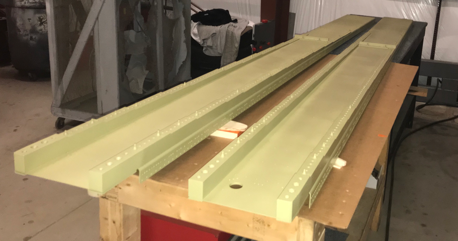
UPS brought the Akzo on time, so here’s the Left and Right Main Spar after priming. Tomorrow we will start installing all the nutplates.
We started today’s session with hole deburring and edge work on the four Wing Box J-Channels for the Right Main Spar. They are labeled and will now be set aside with the one’s from the Left Main Spar to be used on Section 20-Bottom Wing Skins.
Next, we final-drilled the remaining #40 holes in the Right Main Spar Upper and Lower Flanges and the tip and root of the web. Moving on to countersinking. To start, we countersunk the nutplate attach holes “just deep enough to fit the head of an AN426AD3 rivet”.
Here is the Upper Flange on the Right Main Spar with all the nutplate attach holes countersunk.
Here is the Lower Flange on the Right Main Spar with all the nutplate attach holes countersunk.
The three nutplates on the Right Main Spar web root.....
And the four nutplates on the Right Main Spar web tip.
I was under the impression (wrong impression as it turns out) that all the countersinking was complete.....IT WAS NOT! All of the remaining #40 holes in the Left and Right Main Spars have to be countersunk to accept a dimpled skin. So, countersinking continues. In order to get the correct countersink depth, I used a piece of scrap material (same thickness as the Wing Skins) and dimpled a guide. I purposely countersunk the hole to shallow and used the guage I made to slowly creep up on the correct depth.
Here is the completed Right Main Spar Lower Flange with ALL the holes countersunk. (The only exception is the center holes of the nutplates. There is a process outlined in the plans I will use to make those countersinks).
This is the completed Right Main Spar Upper Flange with ALL the holes countersunk. (The only exception is the center holes of the nutplates. I will use the same procedure in the plans to make these countersinks).
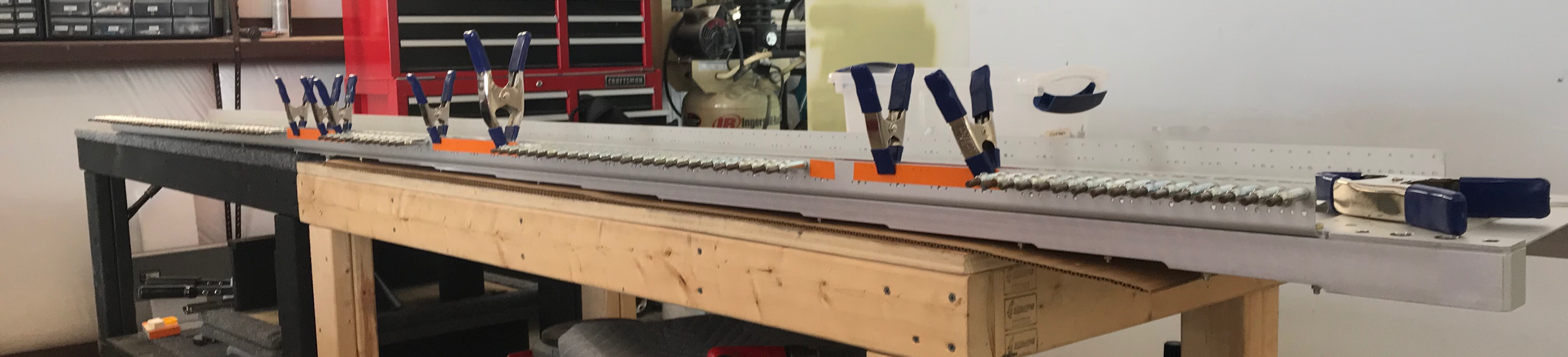
The Wing Box J-Channels are installed here on the Lower Flange of the Right Main Spar. As with the Left Spar, we marked off the holes that do not get match-drilled (at this time) with orange tape. We used a square again to make sure we had the 1/16” rise between the Main Spar Flange and the top of the J-Channel. It worked just as good on the Right Spar. (Note: Part 2 provides further details and pictures regarding how we used the square in this step)
As the plans instruct, we installed clecos in each hole as we completed the match-drilling down the length of the Spar. This is the completed Lower Flange, minus the holes covered by the orange tape. Once we complete the J-Channels on the Upper Spar Flange, we will “roll” the Lower J-Channel to the Upper Flange.....just like on the Left Spar. (Note: Part 2 provides further details and pictures regarding this step)
There is a lot of holes in these Spars. In the picture below, you can see the competed Upper/Lower Spar Flanges and J-Channel with all the clecos installed. The last step is to remove the Upper J-Channels, roll the Lower J-Channels (to the Upper Flange), and match-drill the remaining holes that were covered with the orange tape. Confusing I know, but it’s pretty straight forward when you actually do it.
Tomorrow, we will final-drill the several remaining holes (that weren’t match-drilled) in the Upper/Lower Flanges and all the nutplate attach holes. After that, the nutplate attach holes get countersunk.
This session started by final-drilling #40 the remaining .094 holes and the nutplate attach holes in the upper and lower flanges of the Left Main Spar Assembly. Additionally, there are four nutplate attach holes in the tip of the Left Main Spar and three at the root the need to be final drilled to #40.
These are the four in the tip.....
And these are the three in the root.....
Since these holes are already pre-punched from Van’s, I used a #40 reamer to final-drill.
Now on to COUNTERSINKING! The plans caution you to only countersink deep enough to fit the head of a AN426AD3 rivet. First, the nutplate attach holes on the Main Spar Flanges get countersunk #40. Secondly, the nutplate attach holes in the web tip and root get countersunk #40. And lastly, the 14 holes for the Wing Ribs get countersunk #40. Here are a few pictures after all the holes are countersunk. I put the orange tape on to cover the gap between the Main Spar and Flange to keep metal shavings from getting in the crack.
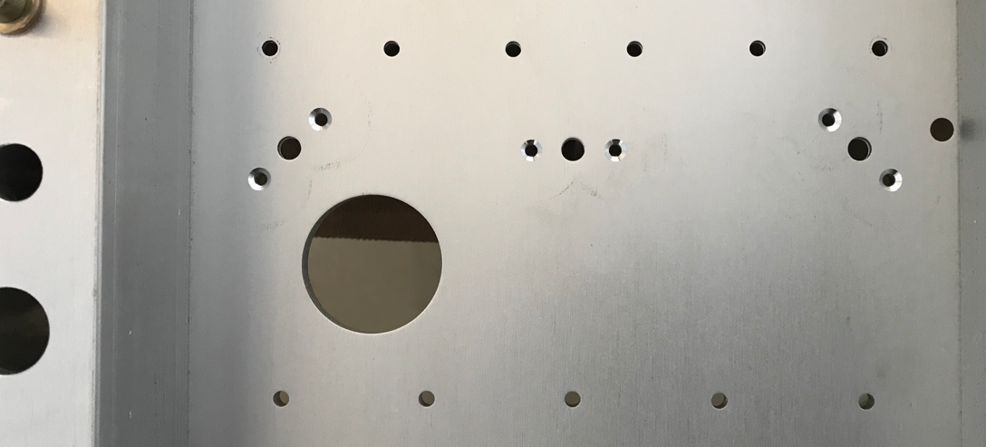
Outboard Main Spar Web.....
Inboard Main Spar Web.....
Alright, according to the plans I need to install the Fuel Tank Skin attach nutplates to the Left Main Spar. However, I would like to prime the Left Main Spar first. So, we will move on to preparing the Right Main Spar up to this point and I will prime them together at the same time.
I started the Right Main Spar the same way I did the Left.....by labeling the correct orientation of the Spar.
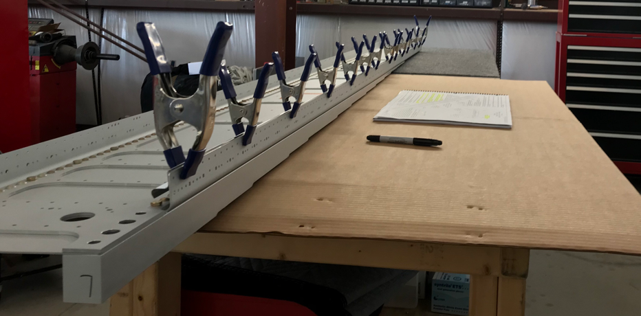
Now we have to cut four (two each side) Wing Box J-Channels for the Right Main Spar. This picture shows two already cut to length (clamped on the Right Spar Flange) and the remaining J-Channel.
We started today by making sure our measurements were still correct from yesterday (measure lots of times and drill once.....I’m learning)! This picture shows (tough to see) the Wing Box J-Channel (as they are called) clamped on the inside of the Lower Left Main Spar Flange. The three areas that have orange tape are holes that DO NOT get match-drill at this time.
The plans call for a 1/16” rise between the edge of the Main Spar Flange and the edge of the J-Channel. To do this, we used a square set to 1/16” to verify the distance. You can see the “rise” of 1/16” in the picture below.
Here are the first 18 holes in the Lower Spar Flange. The plans instruct you to monitor the position of the J-Channel relative to the Spar Flange as you progress with match-drilling to ensure the correct distance. We used the square on every two holes to verify the correct distance. I don’t know if you have to be this anal about it, but it’s 1/16” all the way across.
Below is the entire lower flange after all the match-drilling. Like I mentioned earlier, the holes with the orange tape do not get match-drilled now. In a few steps, the plans will have us roll the Lower Spar J-Channels 180 degrees to the Upper Spar and finish the match-drilling process. I’ll show a few pictures when we get there.
This is the same picture with the clamps removed.
Here we “fitted” the Wing Box J-Channels to the Upper Left Main Spar using spring clamps to hold them in place.
This picture shows the overlap between the J-Channel Short and Long. With a little massaging, these pieces fit together pretty well.
We match-drilled all 131 holes between the Left Upper Main Spar Flange and J-Channel (forgot to take a picture before removing all the clecos). Now, the instructions says to uncleco the J-Channels from the Lower Flange, roll them 180 degrees, and recleco them to the Upper Flange. The pictures below show the only way I could get the holes to match up correctly (which is rolled 180 degrees) between the J-Channels and the Upper Flange. Now, we have to match-drill the 32 holes from the three sections that we purposely skipped earlier.
This is one of the three sections that needs to be match-drilled (holes between the first two clecos).
After all the drilling, the plans say to set the J-Channels aside for later use in Section 20-Bottom Wing Skins. So, that completes the work on the J-Channels for the Left Main Spar. Now, there are many holes in the Main Spar that need to be final-drilled to #40 and the many nutplate locations that need to be countersunk. We will start there at the next session.