This blog was created to memorialize the building process of my Van's Aircraft RV-14 and to satisfy the requirements for certification in the Experimental Amateur Built Aircraft category. It will also serve as a central location for ME to reference in the future on processes and techniques I used during the build. Additionally, it will allow my family, friends, and other interested builders the opportunity to follow along during my build…..and might be helpful to someone along the way.
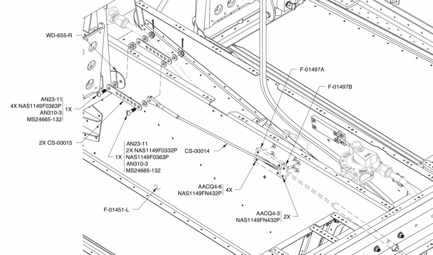
In Part 13, the four Cable Links were Akzo primed and top coated with flat black paint. Now, I will install them on the plane. Here is what the install looks like from the plans and shows the associated hardware.
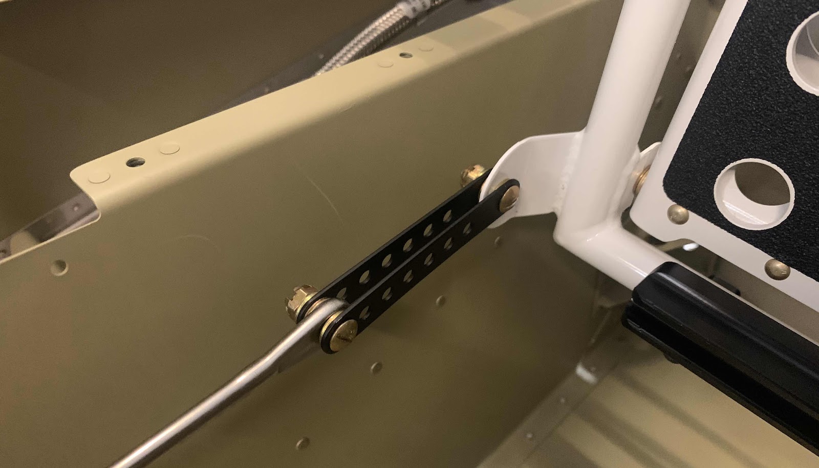
Here is my completed install of the Cable Links on the right (co-pilot) side....
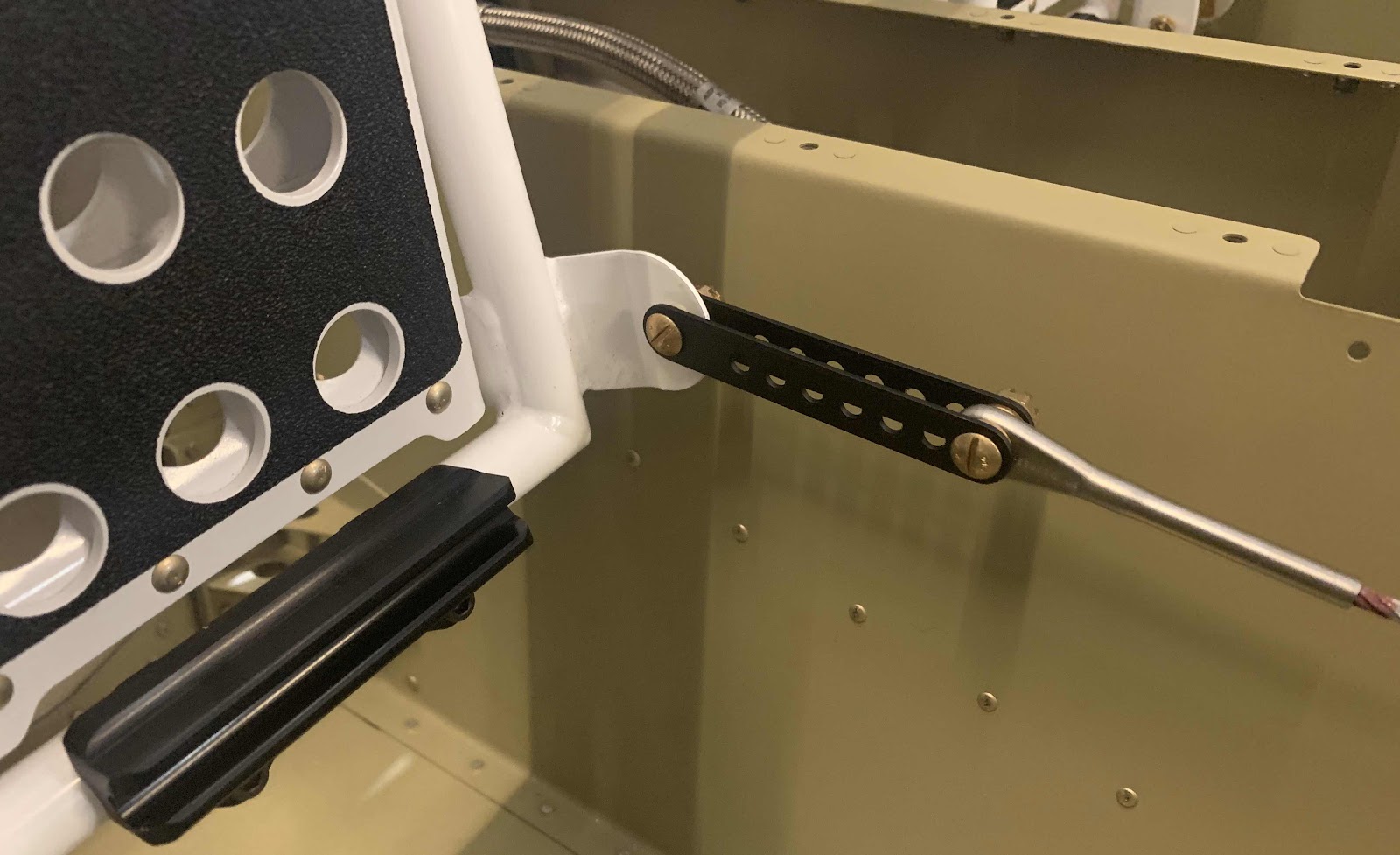
.....and the left (pilot) side.
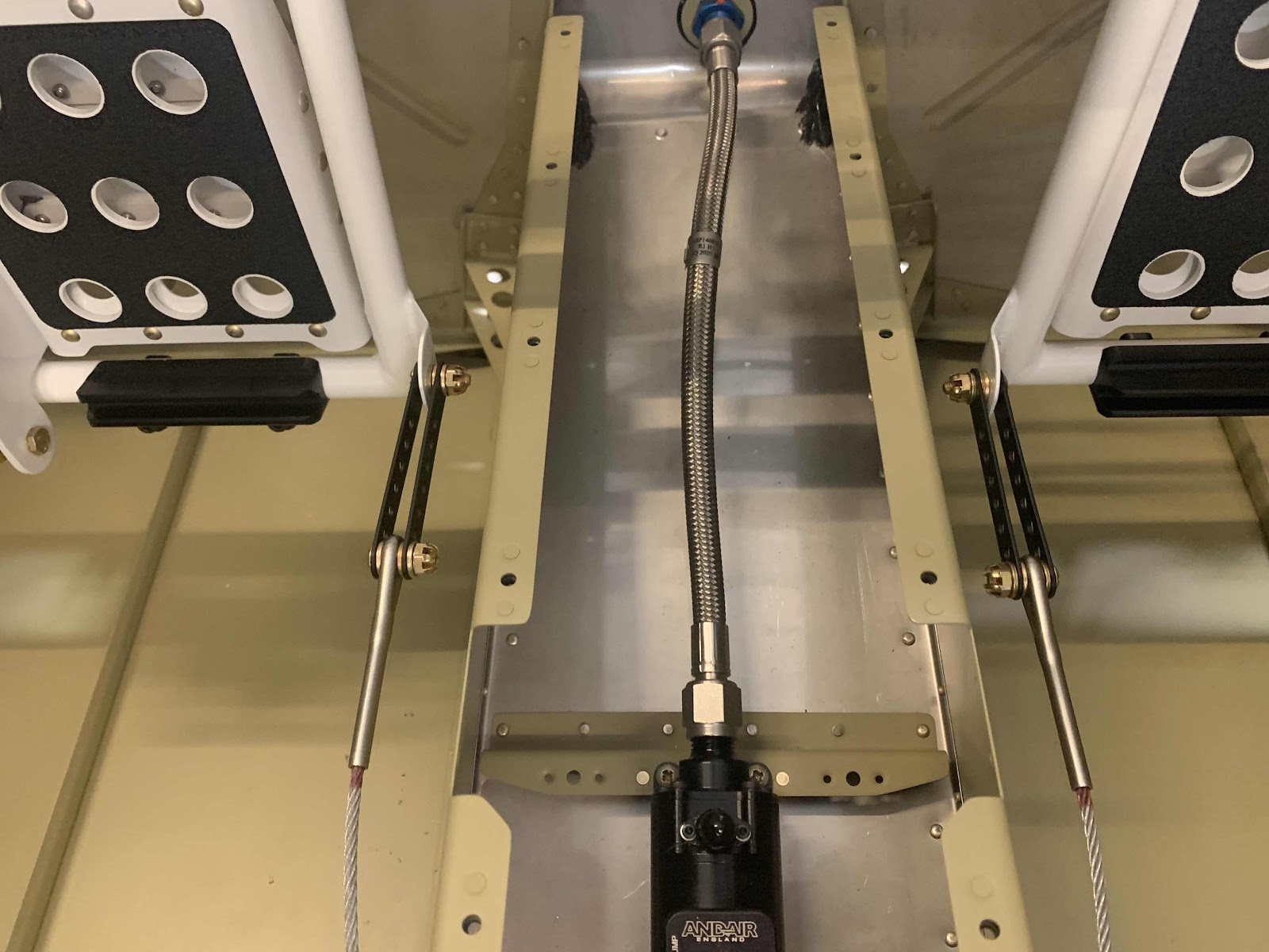
Lastly, here is an overview shot containing both installed Cable Links.
The Rudder Cables are currently connected to the first hole of the Cable Links for reference at this point. I will adjust them in the future (if necessary) when the Rudder Cables are connect to the actual Rudder.
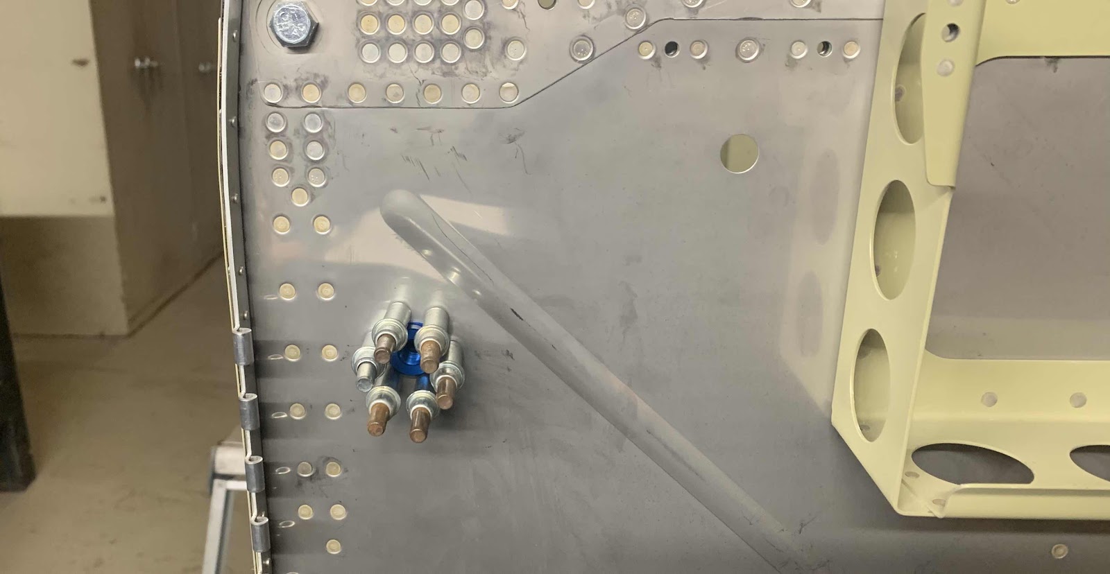
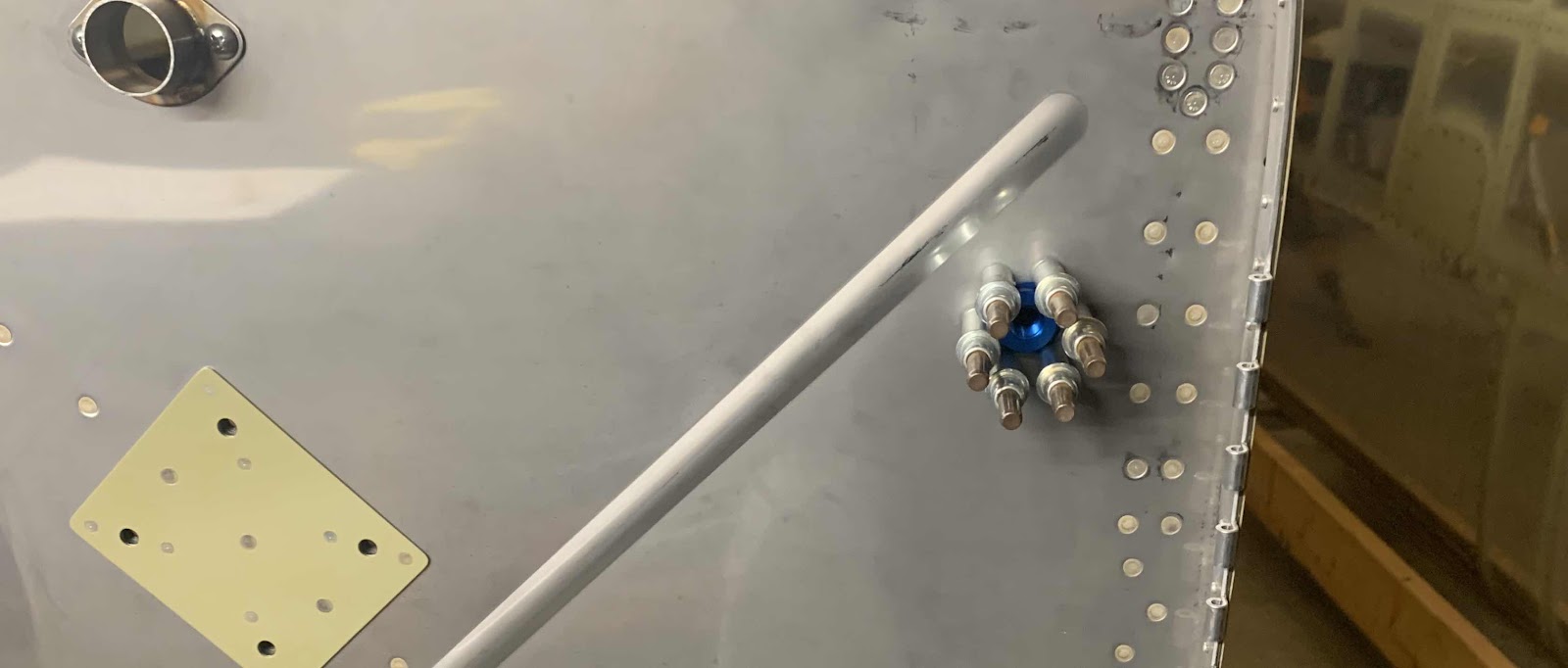
I completed all of the Brake Hose installation in Part 12.....with the exception of the AN826-3D Tee. In the picture below, the blue Tee is final installed with all three connectors. Initially, the Tee was installed into the nipple of the Brake Fluid Reservoir that passes through the Firewall. Then, the two remaining Brake Hoses were installed on the Tee.
Here is an additional view from the other side. That completes the Brake Hose installation!
These are the CS-00015 Cable Links that originally came from Van’s when I ordered the Fuselage Kit. This is what the Florida air does to metal....pretty quickly. I decided not to try and clean these and just ordered a new part from Van’s. So, the Cable Links in the picture below were put in the scrap pile.
After I got the new part from Van’s, I separated and cleaned them up (shown below). Then, I Akzo primed and top coated them with flat black paint. I will show the completed Links in the next session when I install them in the plane.
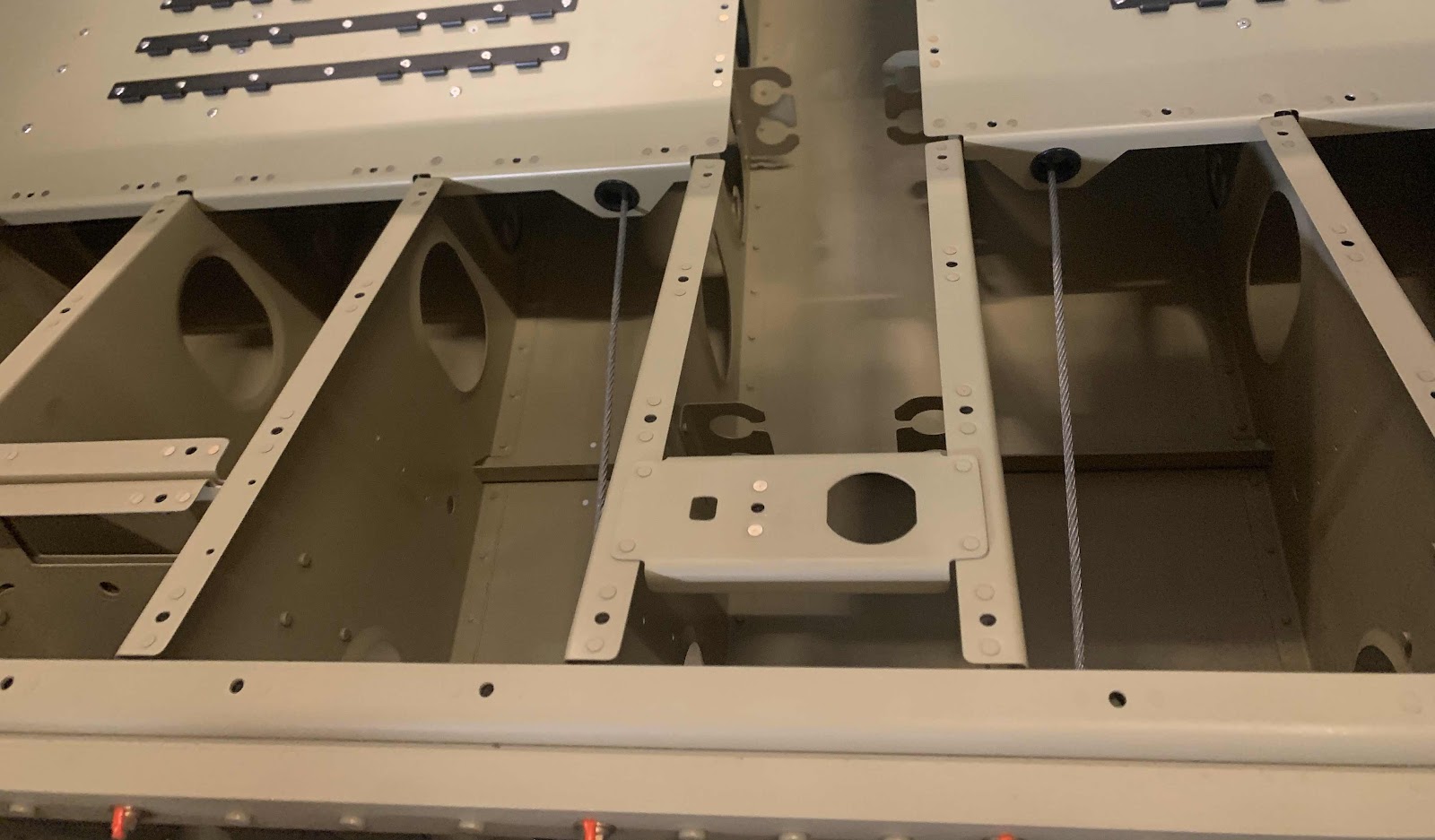
The next step was to install the two F-01497A (large) and F-01497B (small) Cable Guides. In the picture below, you can see two angles of the Cable Guides. The large Guides are installed on the aft side with AACQ4-6 rivets and the small ones on the forward side with AACQ4-3 rivets. You can also see how the Rudder Cables route between the two Cable Guides. This view is from the right (copilot) side looking left (pilot) side.....
.....and the left (pilot) side looking right (copilot) side.
I’ll connect the Cable Links during the next session and complete this section.
As I mentioned in a previous post, it’s time to talk more about the Cabin Brake System from Aircraft Specialty. The picture below shows the completed install of the Stainless Braided Brake Hose kit (minus the AN826-3D Tee installed in the top right corner on the Brake Fluid Reservoir.....more on that later). The hoses are very high quality, covered with a clear abrasion covering and have a 10 year warranty. I used the plans from this section of the plans and the guidance from the Aircraft Specialty website for the install.
This picture shows the hoses final installed to the four -3 size 90 degree AN fittings (AN822 Elbows) on the two Brake Master Cylinders on the right (co-pilot) side. I used this guidefrom the Aircraft Specialty website to torque the hoses to the fittings.
This is the location where the Brake Hoses pass through the F-14104 Support Angle. Now, the hoses that come with the kit from Van’s are smaller in diameter than the ones from the Aircraft Specialty kit. As a result, only two hoses can pass through the hole on the right of the Support Angle (all three of the Van’s hoses are routed through this hole). So, I had to route the third hose (on the left) through an additional hole in the Support Angle. The hole was actually too small for the connector on the Brake Hose to pass through, so I had to enlarge the hole to 1/2” with a step drill. Once all that was completed, I installed a rubber grommet in each hole to complete the pass through.
This shows the hoses final installed to the other four -3 size 90 degree AN fittings (AN822 Elbows) on the two Brake Master Cylinders on the left (pilot) side.
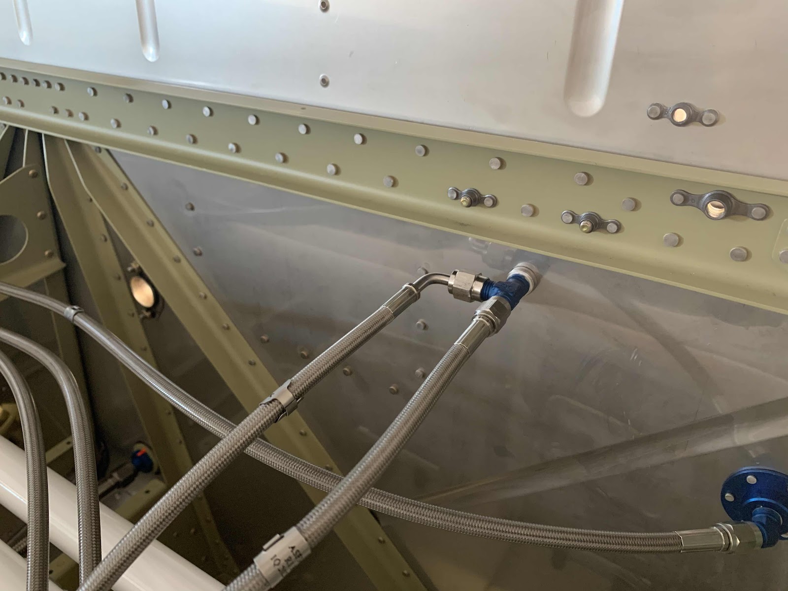
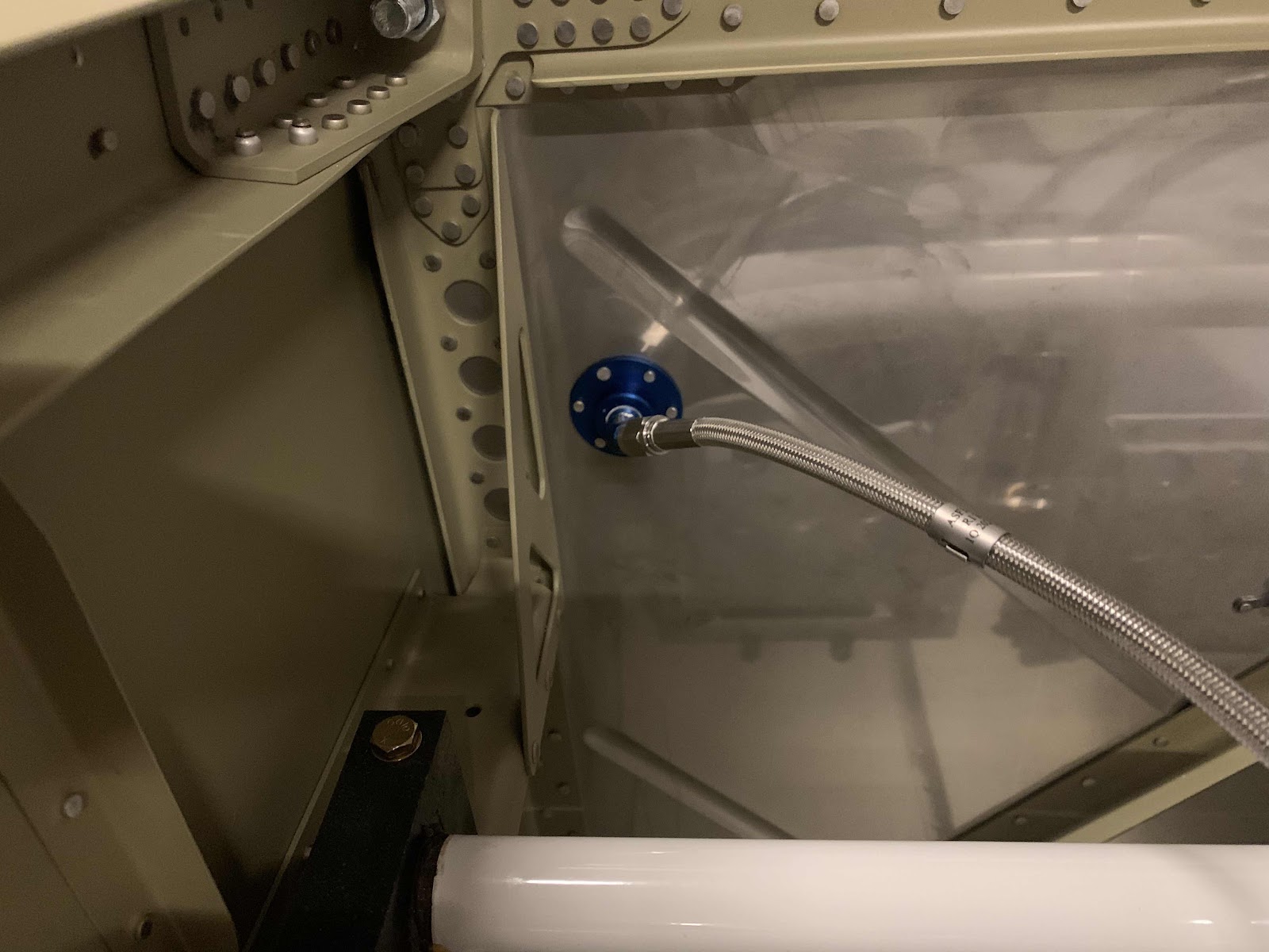
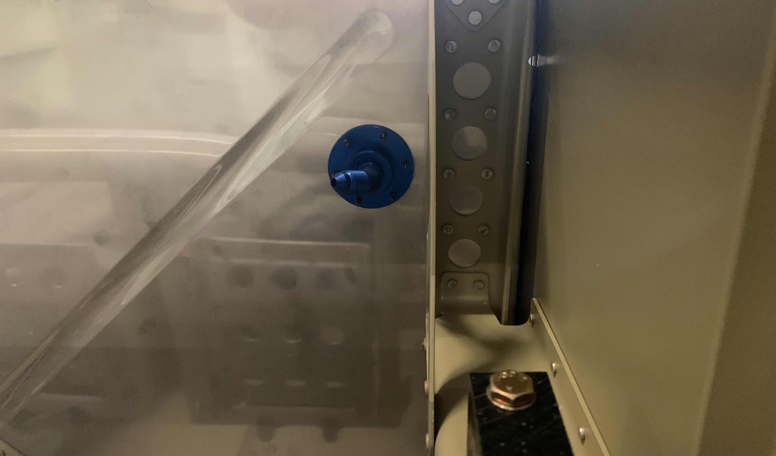
In the center of this picture, you can see the blue Flanged Coupling installed on the right (co-pilot) side. The Brake Hose is final attached to it with an AN823 45 degree elbow.....
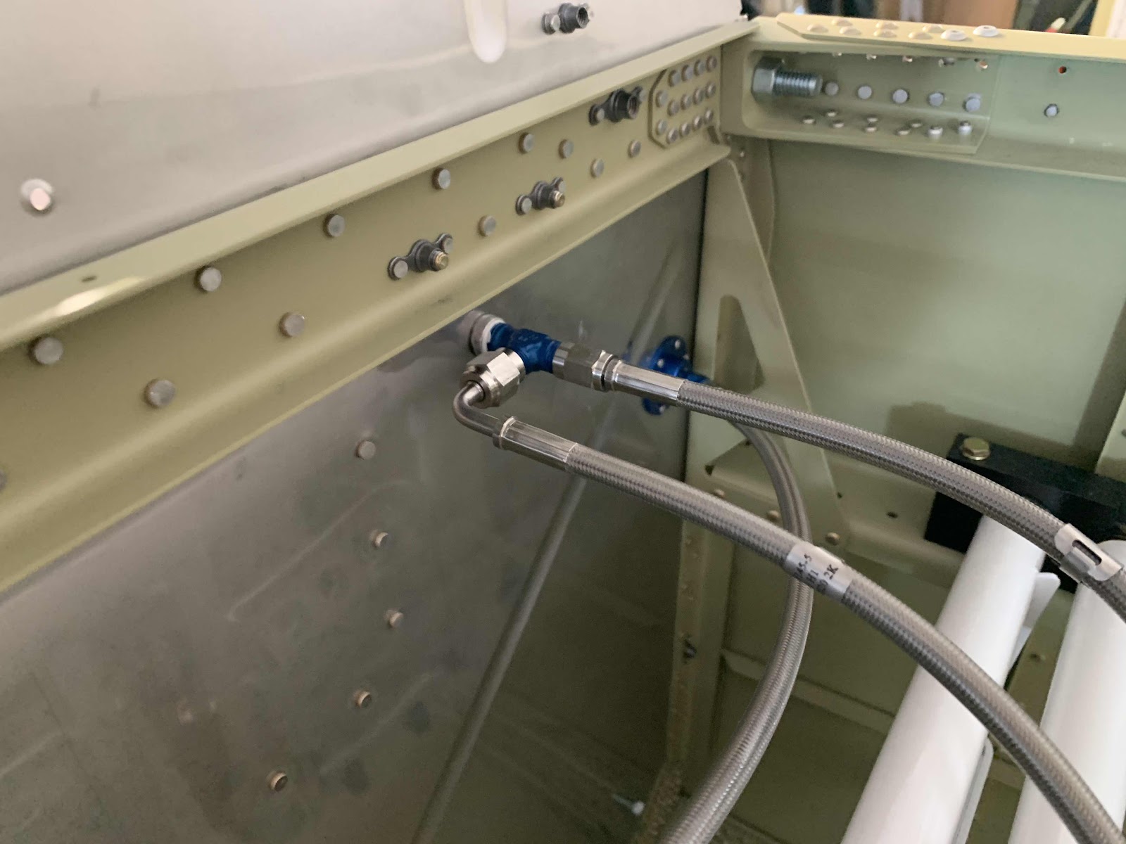
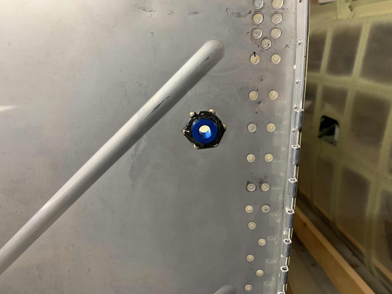
.....and installed the same way on the left (pilot) side.
As I mentioned at the beginning of the post, all of the Cabin Brake Hoses have been completely installed.....minus the AN826-3D Tee fitting. I will install this fitting during the next work session. This Tee fitting will be installed between the three connectors shown in the picture below. So, for now.....this work session is complete.
In Part 10, I drilled the two 13/16” holes in the Firewall and match-drilled the six holes in the flanges for the two FLF-00010 Flanged Couplings. Tonight, I riveted them in place using AN470AD3-3.5 rivets. This is the Flanged Coupling installed on the right forward side of the Firewall. From this view, you can see the manufactured heads on the Firewall (as instructed by the plans) and the proseal I put on the forward right side of the Flange/Firewall. Just like before, I applied proseal to the side of the Flange that will mate with the Firewall and “smashed” it into place.....installed clecos and then the rivets.
Here is the completed right side (aft) following the install of the six rivets and all the excess proseal removed with MEK.
This is the left side (forward) of the Firewall. This side was installed the same way as the right side.
And the aft side of the left Coupling after installing the six rivers and removing the excess proseal with MEK.
Now, to install these rivets, you will have to use a “reduced diameter” or “tapered” rivet set. The one I have is on the right and would NOT fit squarely on the manufactured head of the rivet because of the Coupling. So, I had to use my buddy’s on the left. This one worked great and fit perfectly on the head of the rivet.
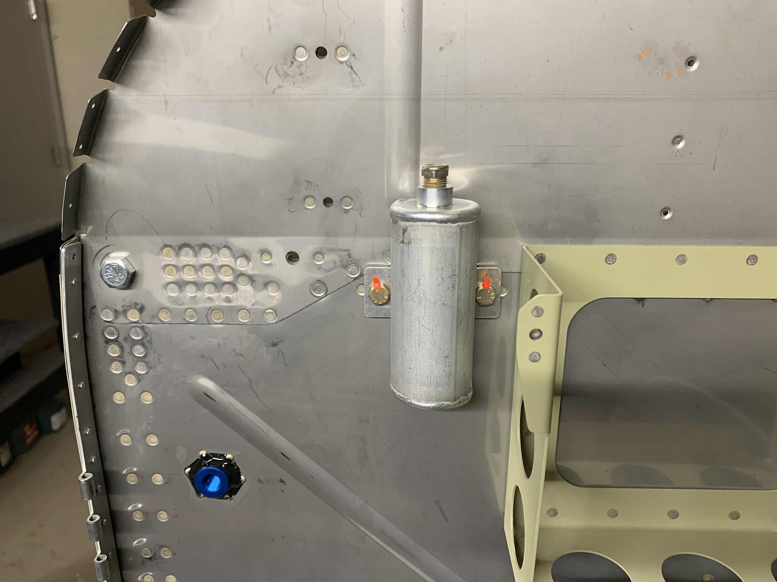
The next piece to get installed on the Firewall is the VA-107 Brake Fluid Reservoir. It is held to the Firewall with two AN3-5A bolts into previously installed nutplates.
When the Reservoir was installed through the Firewall, proseal was applied to the Reservoir nipple. In the picture below, you can see the black “ring” of proseal around Firewall pass through.
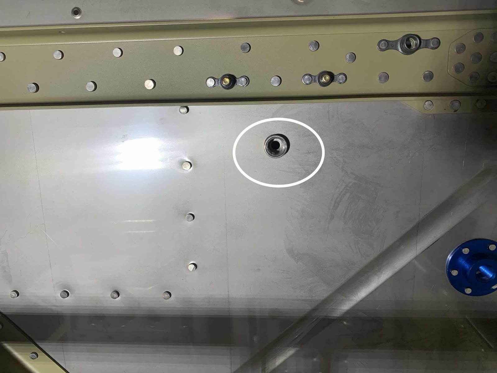
Circled below is the Reservoir nipple that passes through the Firewall. I decided not to put any Proseal on this side of the Firewall because of how good the seal was on the front side. I might change my mind later, but for now I’m going to leave it alone.
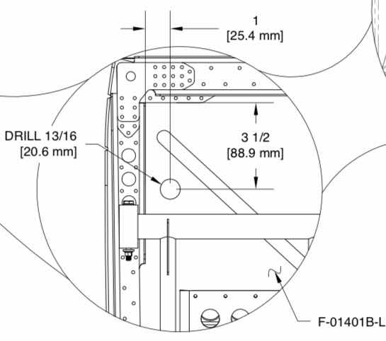
Since I’m building an RV-14 (versus RV-14A), I had to drill two 13/16” holes through the F-01401B-L & -R Firewall Sides. The measurements were taken from the cockpit side off the Firewall as indicated in the plans excerpt below......3.5” down and 1” inboard. The plans instruct you to measure on the aft side of the Firewall and drill from the forward side of the Firewall. So, I figured out where the center was based on the measurements below and used a #40 bit to drill a pilot hole on the aft side. Then, I used my step drill from the forward side to enlarge the hole to 13/16”.
Once the two 13/16” holes were drilled through the Firewall (very nervously might I add), the FLF-00010 Flanged Couplings (blue part in the center of the clecos) were inserted into the holes, centered and the six #40 holes in the Flanges were match-drilled in the Firewall. Below is the forward side of the right Coupling clecoed to the Firewall.....
.....and the aft side of the right Coupling.....
.....forward side of the left Coupling.....
.....aft side of the left Coupling.
I’ll complete the remaining step regarding the Couplings install when I get some proseal.
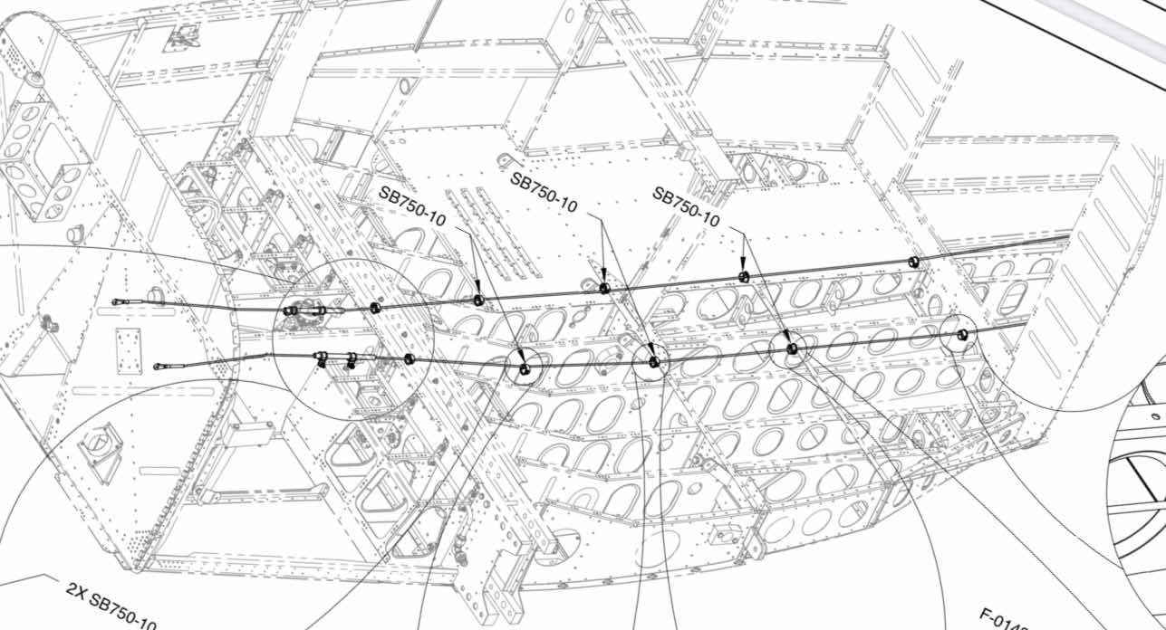
In the meantime, I went on to the routing of the Rudder Cables through the Fuselage as shown below.
This is looking aft through the rear Fuselage.....
.....through the seating area.....
.....and outward toward the Rudder Pedals (on the left).....
.....and on the right.
This is a close up of the polyethylene sleeve that the Rudder Cable will run through near the Fuel Lines. It will eventually get clamped to the Rib next to it. This is the left side.....
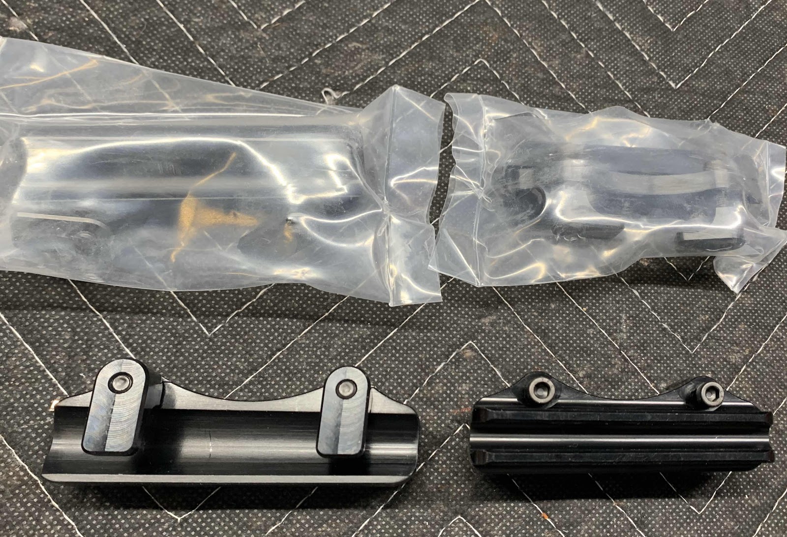
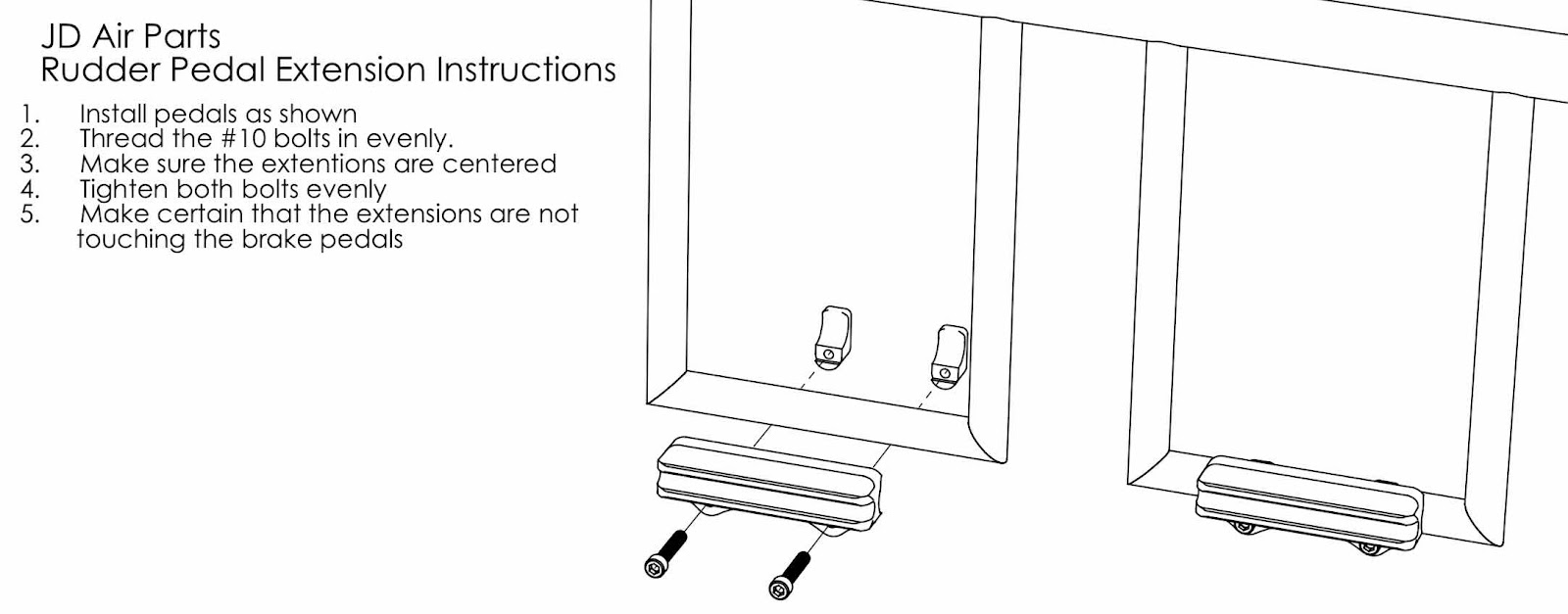
Very short session tonight, but we added some “bling” to the Rudder Pedals. A couple of weeks ago, I ordered the JDAir.com Rudder Pedal Extensions for RV Aircraft. The Extensions are 3.5 inches long, CNC machined from aluminum and hard anodized for wear resistance. They are designed to clamp onto the existing 5/8” diameter Rudder Pedal tubes.
“Our Pedal Extensions improve the RV rudder/brake to foot geometry so it’s much easier to taxi, take off, land and use full rudder deflection without inadvertently touching the brake pedals”.
Here are the four Extensions right out of the box. (I already removed the plastic from the two on the bottom).
This is a copy of the mounting instructions from the website. Very, very easy to do!
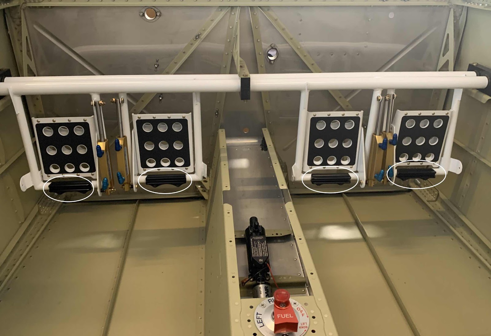
While doing some research, I’ve read several posts in the Van’s Air Force Forums regarding the Rudder Pedals and how pilots sometimes inadvertently apply pressure to the brakes when operating the Rudders. Now that the Assemblies are completely together, I can see how this could possibly happen. So, I decided to order the extensions and install them now.....since most of the forward Fuselage is still pretty open. The install only took a few minutes and they look great. I only have them snug to the Rudder Pedals at the moment. If necessary, I will make any final adjustments once I can sit in the plane and see what “feels” right.
Here are the four Rudder Pedal Extensions installed on the Rudder Pedals. (Circled below)
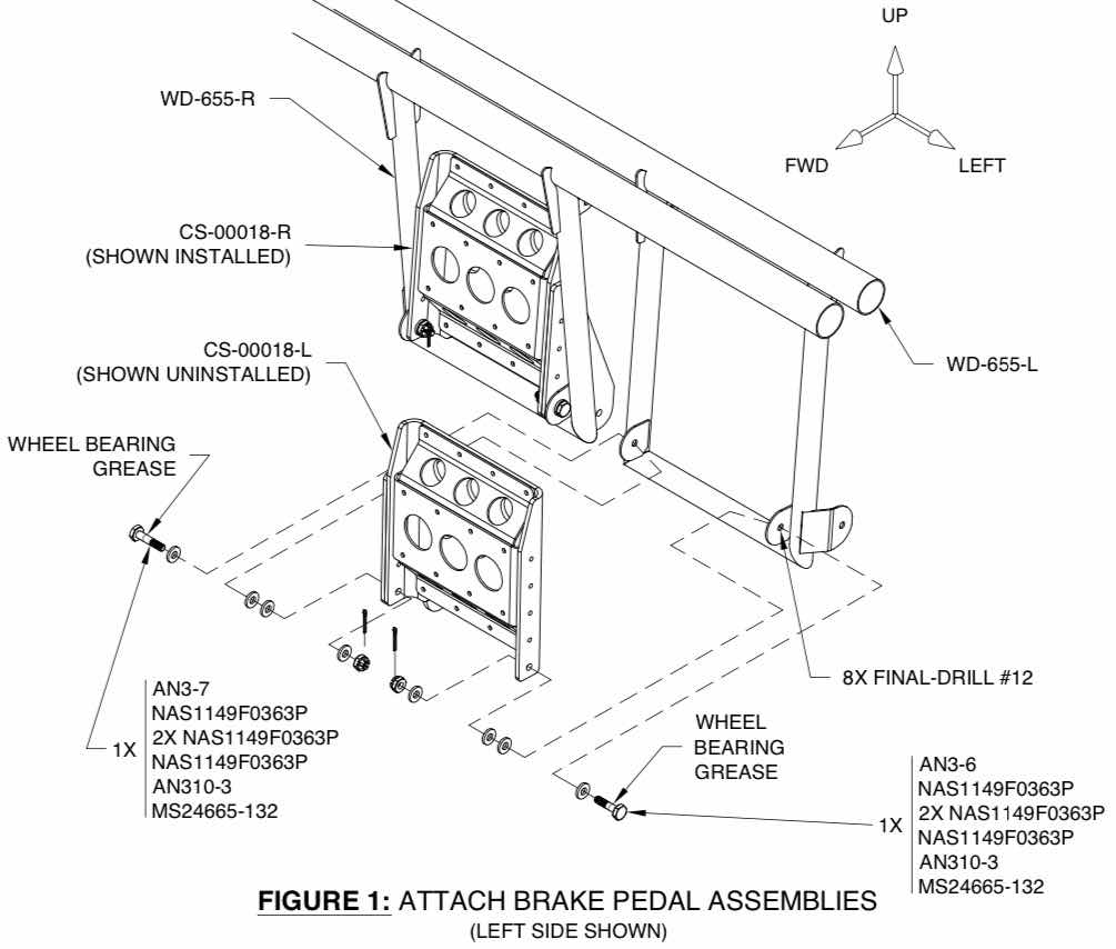
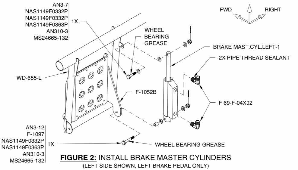
Today’s session was very long and very productive. To start off, the CS-00018-L & -R Left and Right Brake Pedal Assemblies were attached to the WD-655-L & -R Rudder Pedals. The plans call for a mixture of hardware to make the attachments. Here is what the plans recommend:
The plans also make three statements regarding this portion of the installation:
1. “A balance must be struck between free play and friction such that both are minimized. The brake pedal assemblies much be secure but must also rotate by gravity alone before the cotter pins are installed”.
2. “Due to manufacturing tolerances, it may be necessary to use a different mix of washers than what is shown in Figure 1. If required, use a heavy soft-faced hammer to make slight adjustments to the brake pedal mounting tabs”.
3. “Tighten the nuts and bolts until they are finger-tight. DO NOT use standard torque values”.
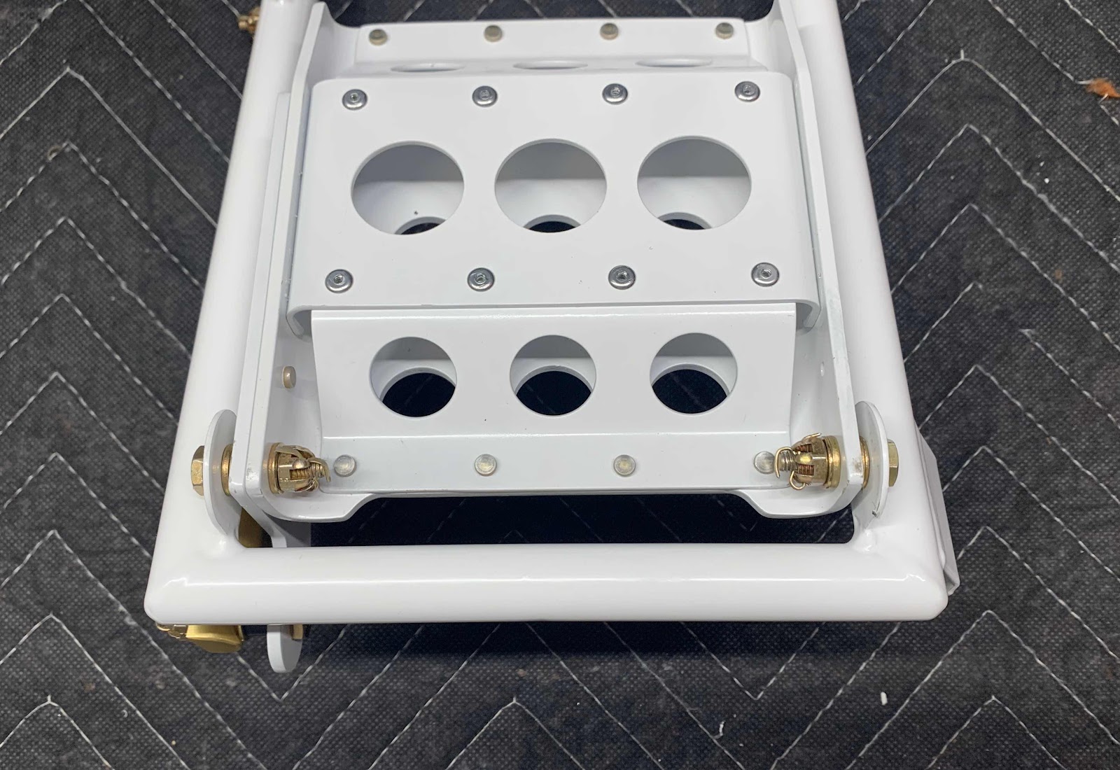
Sooooo, with all that, I started off using the recommend hardware for the installation. However, the hardware used in the final assembly was just a little different than shown above. There wasn’t a huge variation....such as using a skinnier NAS1149F0332P washer versus a fatter NAS1149F0363P washer. It worked out to my satisfaction and, to the best of my knowledge, complies with #1 and #2 above. Here is what the first assembly looks like with the installed hardware.
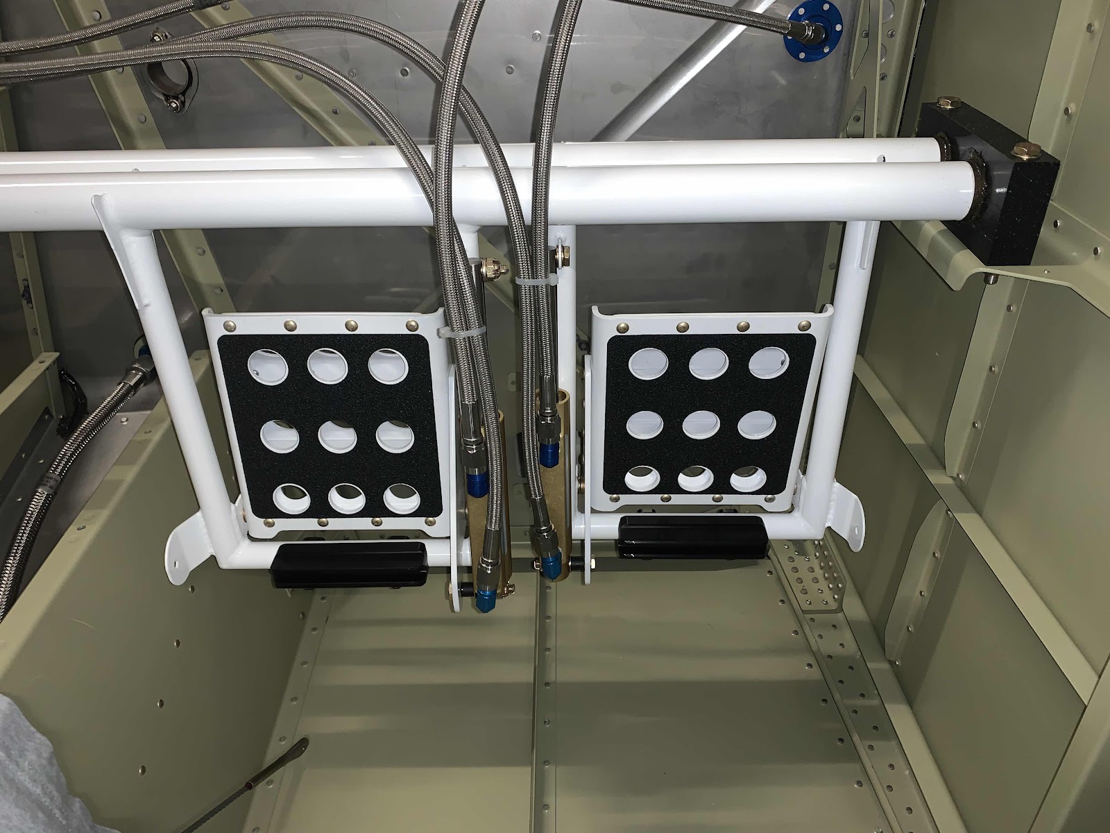
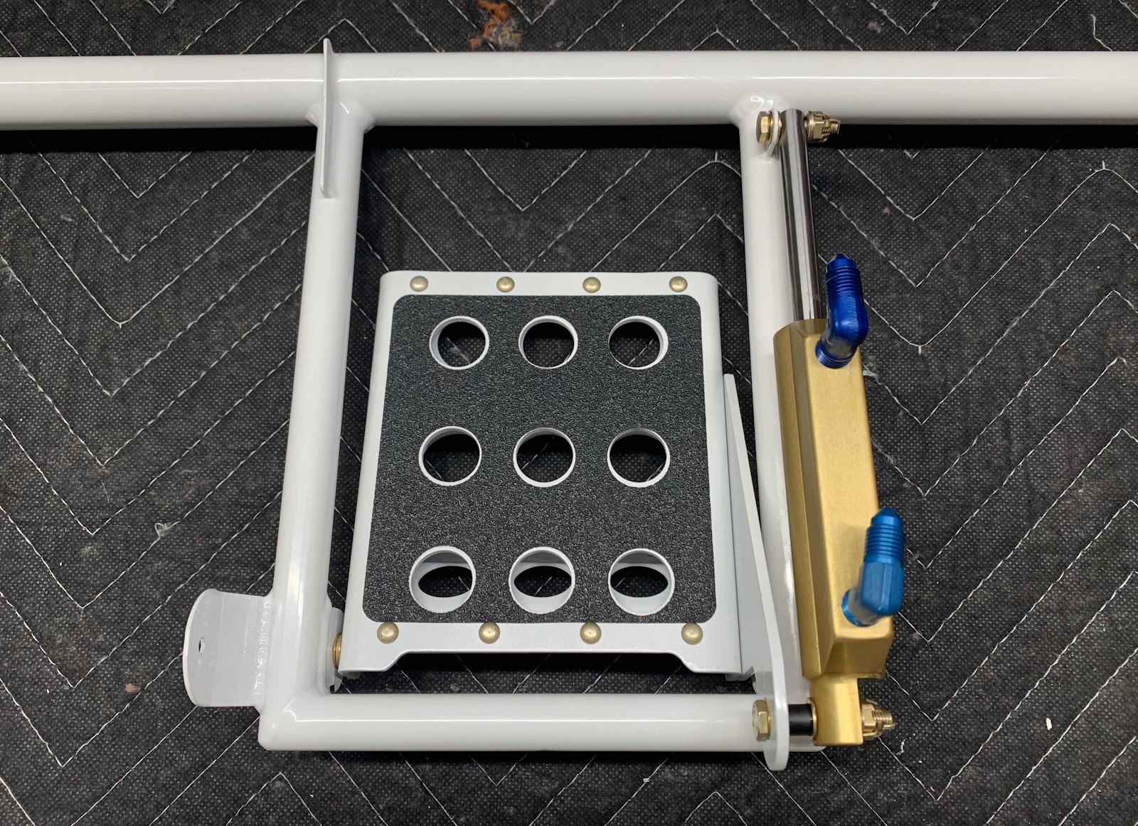
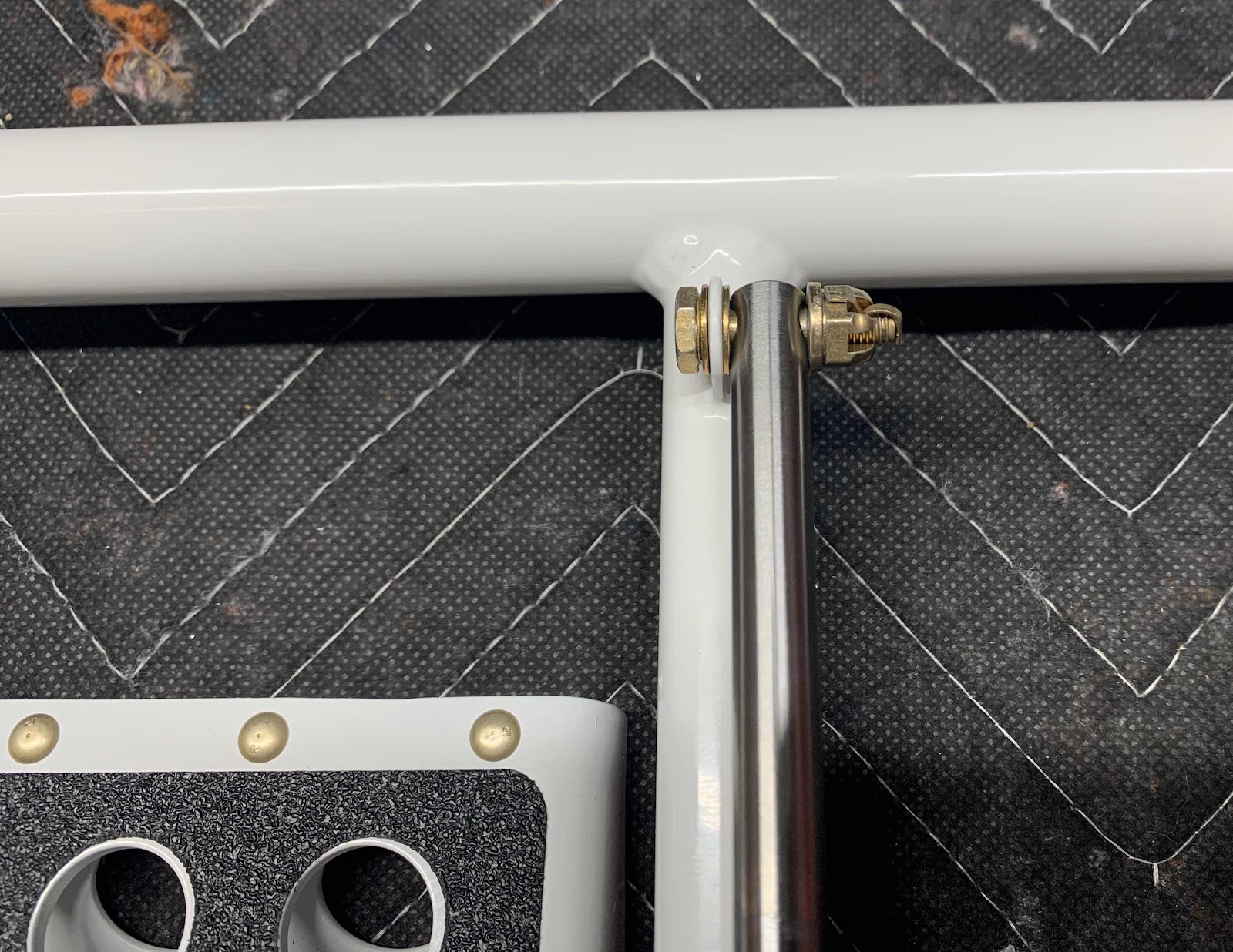
Once I completed all four Brake Pedal to Rudder Pedals assemblies, I moved on to the next step.....attaching the four Brake Master Cylinders to the same assemblies. Here is how they get assembled.....
In the picture below, you will notice the two blue elbows attached to the Master Cylinder. These DID NOT come with kit from Van’s. In Section 31, Fuel System, I detailed the purchase and installation of the cabin fuel lines from Aircraft Specialty. I also said I would purchase the Cabin Brake lines from the same company....I did (more on that later). The blue elbows were included in the kit from Aircraft Specialty. Here is the first Brake Cylinder install.....
.....a close up of the bottom.....
......and a close up of the top.
These are the Rudder and Brake Pedals for the pilot side (left).....
.....and the co-pilot side (right).
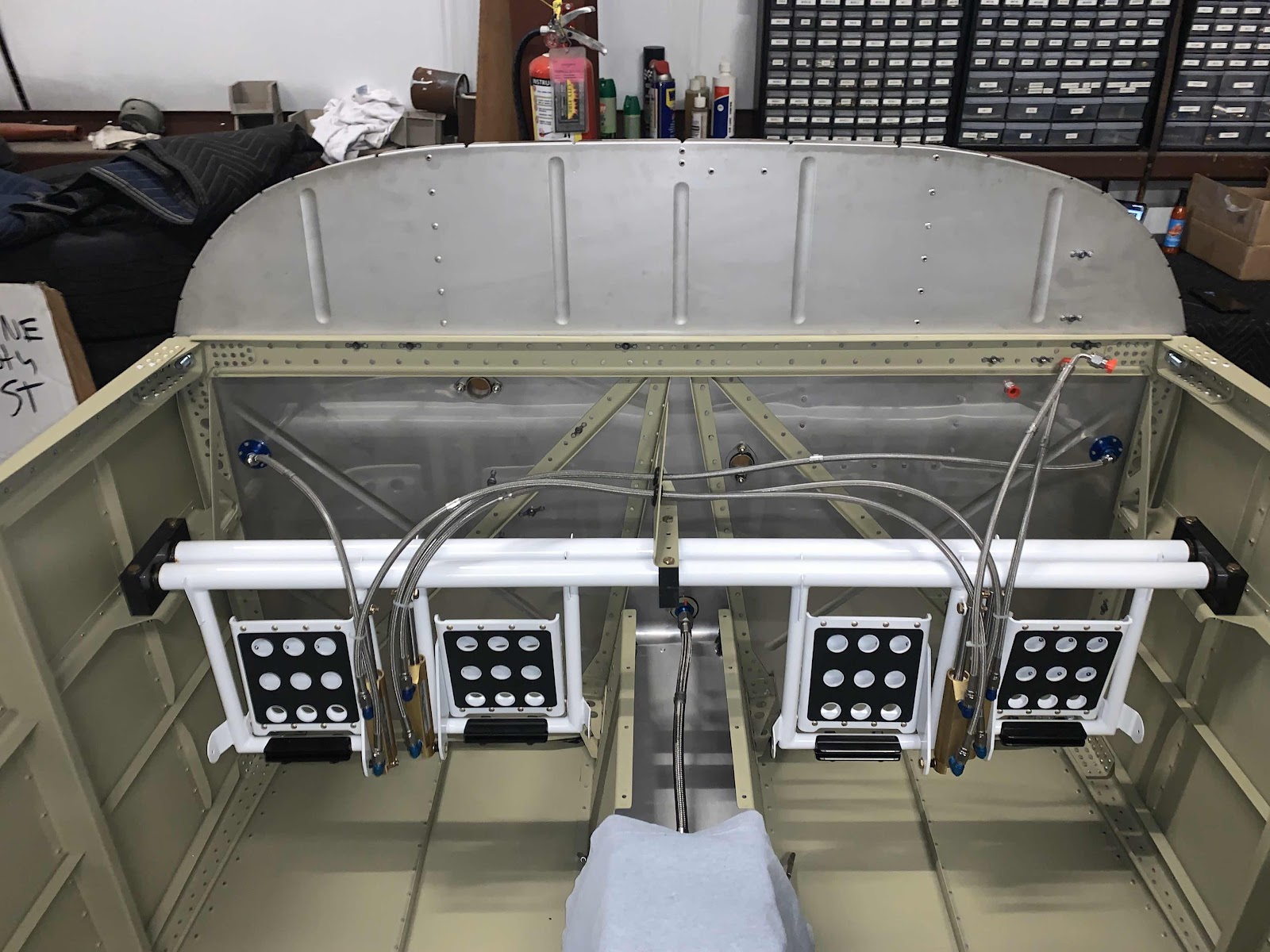
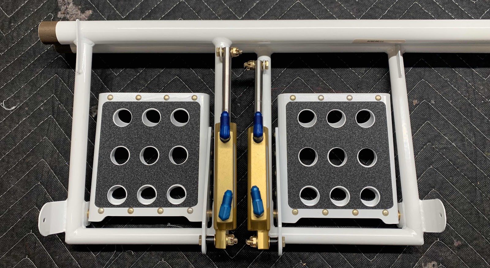
This is an overall view of all four Brake Pedals attached to the four Rudder Pedals.....
.....and what they will look like in the plane.
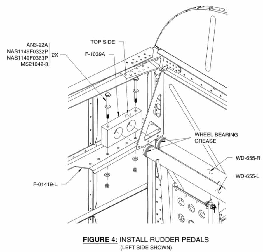
The next step is to install the Assemblies to the airplane. Here is the install procedure from the plans. The ends of the Rudder Pedals are coated with AeroShell #5 grease prior to being inserted into the F-1039A Rudder Pedal Bearing Blocks (prepared in Part 6). The Bearing Blocks were then attached to the airplane with the indicated hardware.
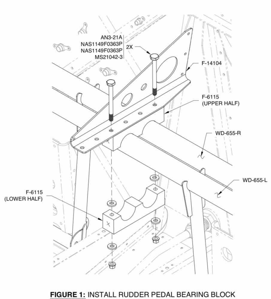
Once the left and right sides were installed to the airplane, the Upper and Lower Halves of the F-6115 Bearing Blocks were installed as shown below.