Showing posts with label Section 34-Flap Actuation System. Show all posts

Saturday, March 21, 2020

Fuselage, Flap Actuation System (Part 2)

During the last session, I installed the two Flap Torque Arms and Flap Crank.  Today, I will prepare and install the ES 85615-10 Linear Actuator (Flap Motor).  The first step is to drill an angled “1/16” hole through the upper lip of the extension shaft and should exit outside the profile of the jam-nut, but within its outside diameter”.  All of those words look like this in the plans.....
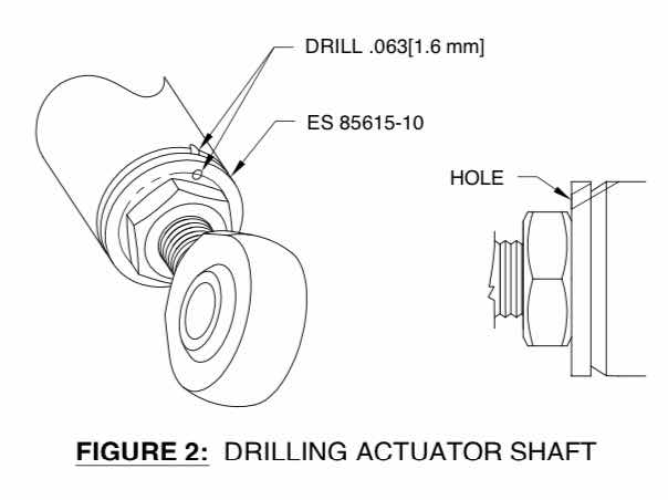
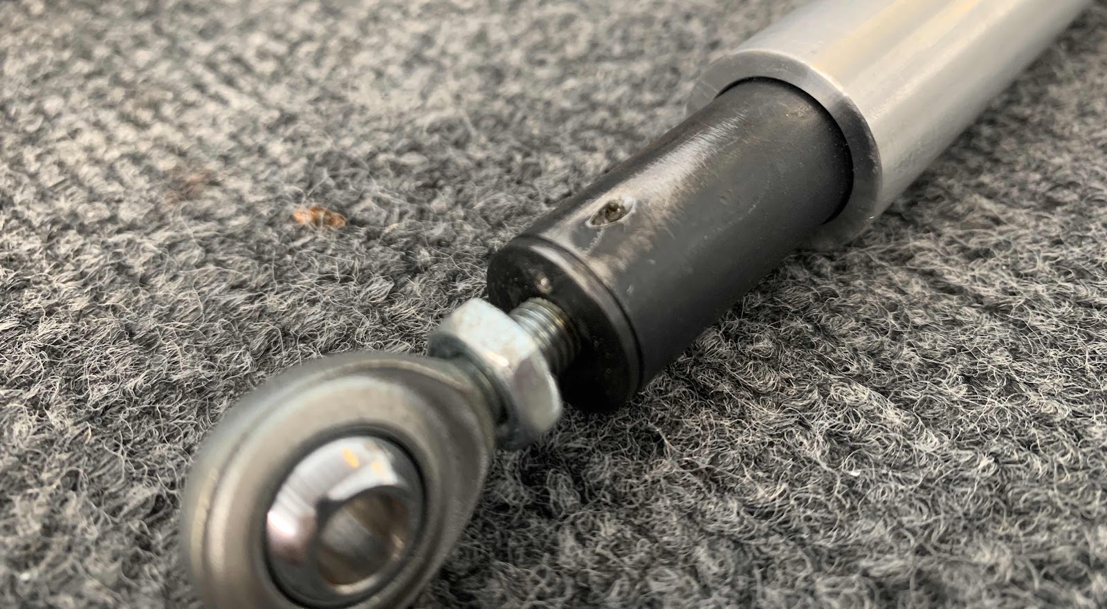
So, here is my 1/16” hole drilled through the extension shaft as described above.  Now, the plans also contain the following NOTE:

“Avoid removal of the ES 85615-10 Linear Actuator jam-nut and rod end since the length of the assembly has been set at the factory”.

In the picture below, I kinda didn’t do that....well sorta!  I initially tried to drill the hole with the jam-nut undisturbed.  However, the drill bit would have drilled partially into the jam-nut (my angle was off ever so slightly).  So, I unscrewed the jam-nut, finished drilling the hole and returned the jam-nut to it’s position from Van’s.
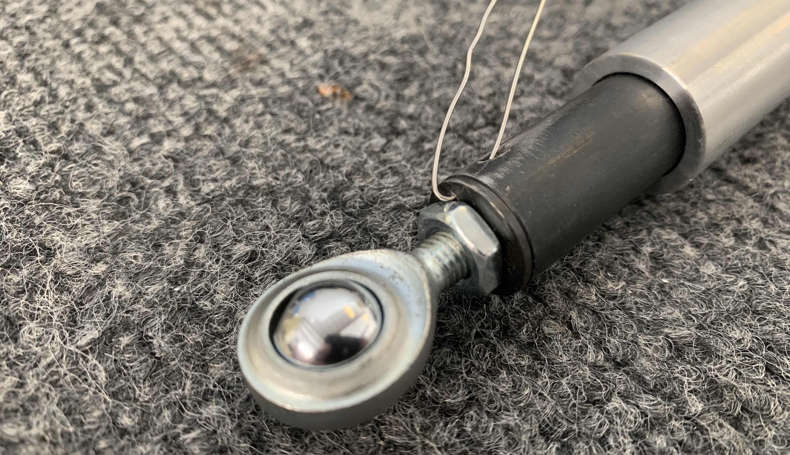
Then, inserted the .025 safety wire into the hole that was just drilled.
While working with the Flap Motor, I saw “Van’s” engraved on the back.  Thought it was pretty cool.

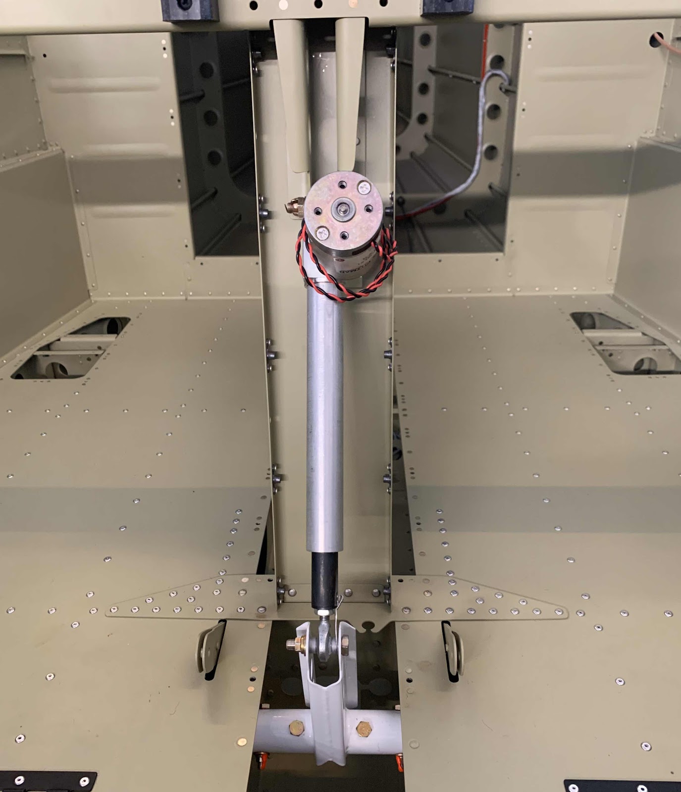
The top of the Flap Motor is secured to the F-01446-L & -R Motor Brackets with an AN4-12 bolt and hardware.  Per the plans, wheel bearing grease was applied to the bolt.

The bottom of the Flap Motor (Extension Shaft) is secured to the WD-1023A Flap Crank with an AN3-12A and hardware.  Additionally, safety wire is routed through the hole drilled in the extension shaft and around the .259X.375X.168 Bushing.

Here is the installed Flap Motor.....BOOM!


Section Complete

I ended up removing the Van's flap actuator and installing a different one.  Please see 
Modifications & Upgrades for the installation of the PH Aviation Services RV Max Flap Actuator.

Thursday, March 19, 2020

Fuselage, Flap Actuation System (Part 1)


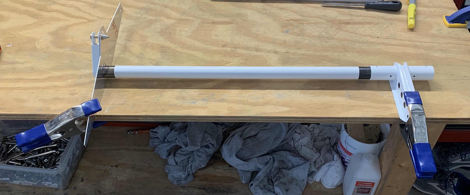
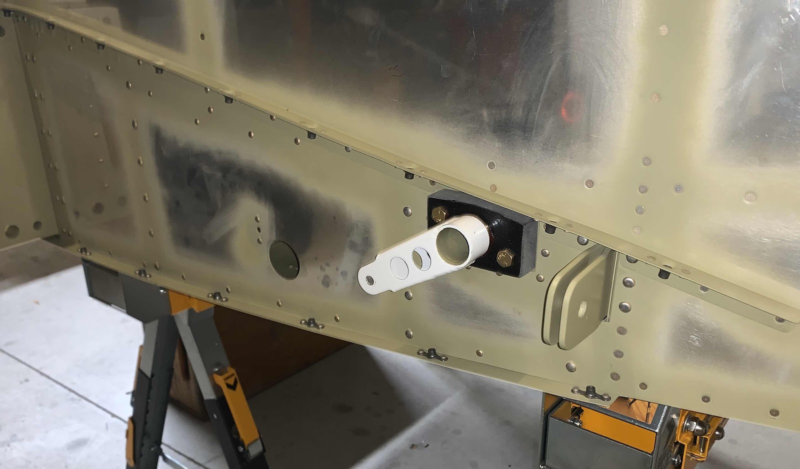
Section 34:  Flap Actuation System only three pages in the plans and should go relatively quickly.  A couple of things are going on in the picture below.  On the right, the first step is to clamp the WD-1013A Flap Crank to the table.  Next, the CS-00010-L Flap Torque Arm is inserted into the W-00026 Alignment Template and secured with the appropriate hardware.  Lastly, the Template is also clamped to the table.  

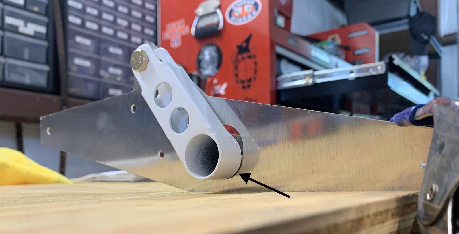
Here is a closer look at the left Flap Torque Arm inserted through the Alignment Template and secured with the appropriate hardware. 

The plans emphasize to make sure the bottom edge of the Flap Torque Arm (arrow) has full contact with the bottom radius of the Template.  Initially, when I tighten the hardware, the bottom of the Torque Arm would rotate slightly and not have full contact.

I investigated as to why.  In the picture below, I circled the hole in the Template the hardware gets installed through.  If you look closely, on the right side of the hole is a “burr”.....there WAS one on the left side also.  I lightly filed the burr off the left side which resulted in full contact of the Torque Arm when the hardware was tightened....problem solved.

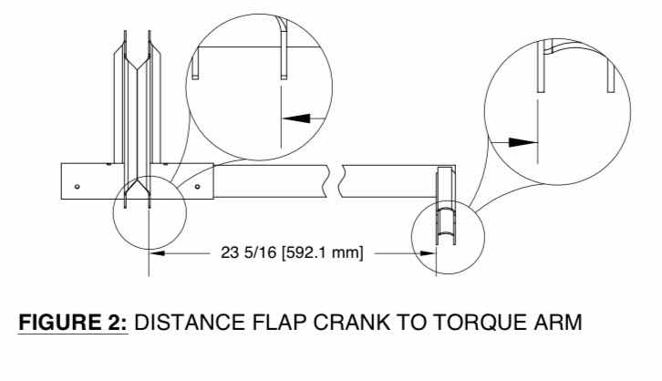
The plans state to position the Flap Torque Arm laterally 23 5/16” from the Flap Crank as shown below.

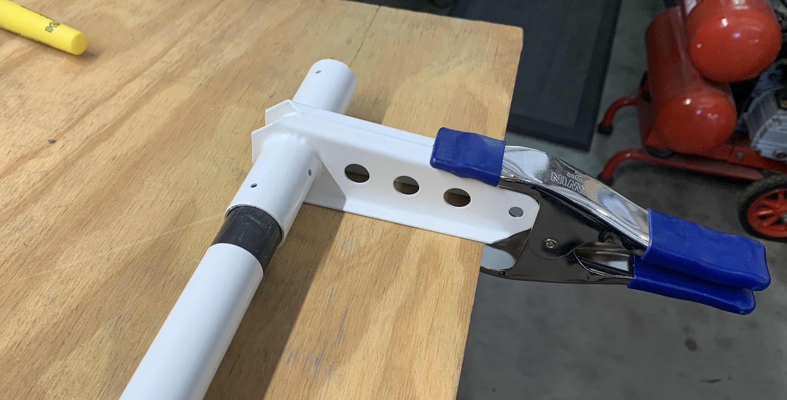
After measuring the correct distance, I clamped everything into place.  As you can see, the Torque Arm doesn’t get installed in the Flap Crank all the way up to the powder coat.  Once this accomplished, the top hole on the Flap Crank is match-drilled #30 into the Torque Arm.  A cleco was inserted into that hole and the hole on the opposite side is also match-drilled #30.  The assembly was unclamped from the table and the remaining two holes were also match-drilled #30.

This picture shows all four #30 match-drilled holes from the Flap Crank through the Torque Arm.  Lastly, the holes were match-drilled #12 all the way through the holes on both sides of the Flap Crank and Torque Arm.  The parts are held together with two AN3-14A bolts.

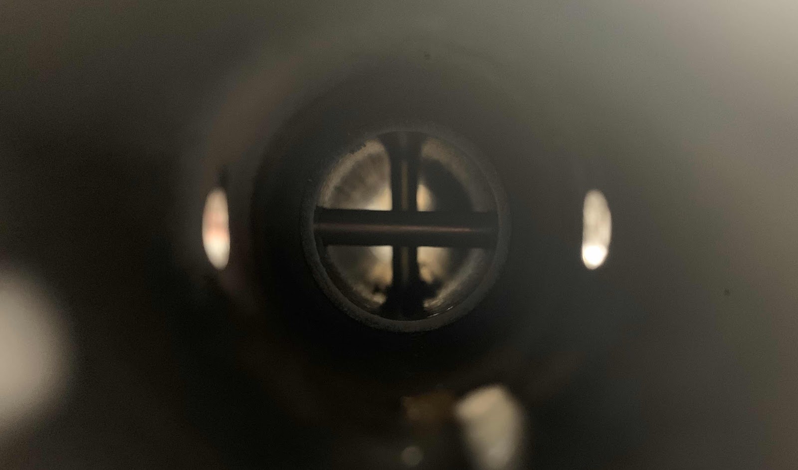
I thought this was a cool picture.  It is looking down the Torque Arm where the bolts pass through the two parts.  This completes the preparation work for the left Flap Torque Arm.  The right Torque Arm was prepared exactly the same way.  I also primed inside the both Torque Arms and Flap Crank prior to assembly.

Each of the Torque Arms were then inserted into the F-1030 Outboard Bushing into the Inboard Bushing.  This is the right side.....

.....and the left side.  Prior to being inserted into the Bushings, the areas on each Torque Arm that was not powder coated were coated with wheel bearing grease.

Both Torque Arms meet in the middle and get bolted to the Flap Crank.  The Assembly was hold together using four AN3-14A bolts.  Here is one view showing the two inside bolts (complete with torque seal).....

.....and the two outside bolts.

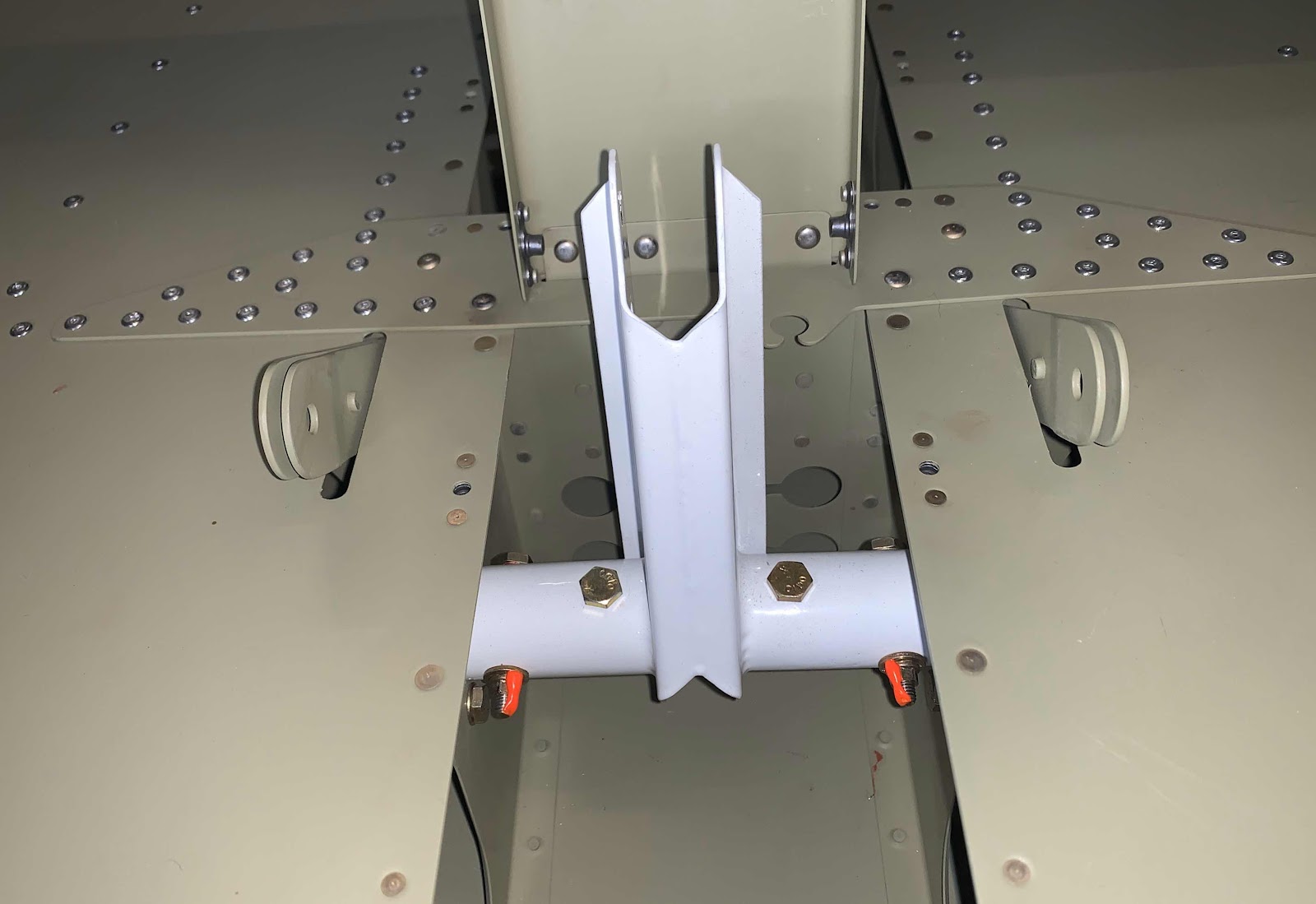
This is an overview of the Flap Crank position and location within the cabin.