In the previous post, the actuator was installed in the RV - minus the electrical connections. In this work session, I completed all the appropriate electrical connections and test ran the flaps using the switch on the panel. The switch, actuator and flaps worked correctly and the whole assembly is very solid. I’m glad I switched to this actuator.
This picture shows the wires pinned with Molex pins and inserted into the Molex connectors. There are five wires that make the appropriate connections, so I used a six pin Molex connector. I decided to install the Molex connector (instead of hard wiring), just in case I need to remove the actuator in the future for any reason. Next, I slid the heat shrink down over the wire bundle and shrunk it into position.
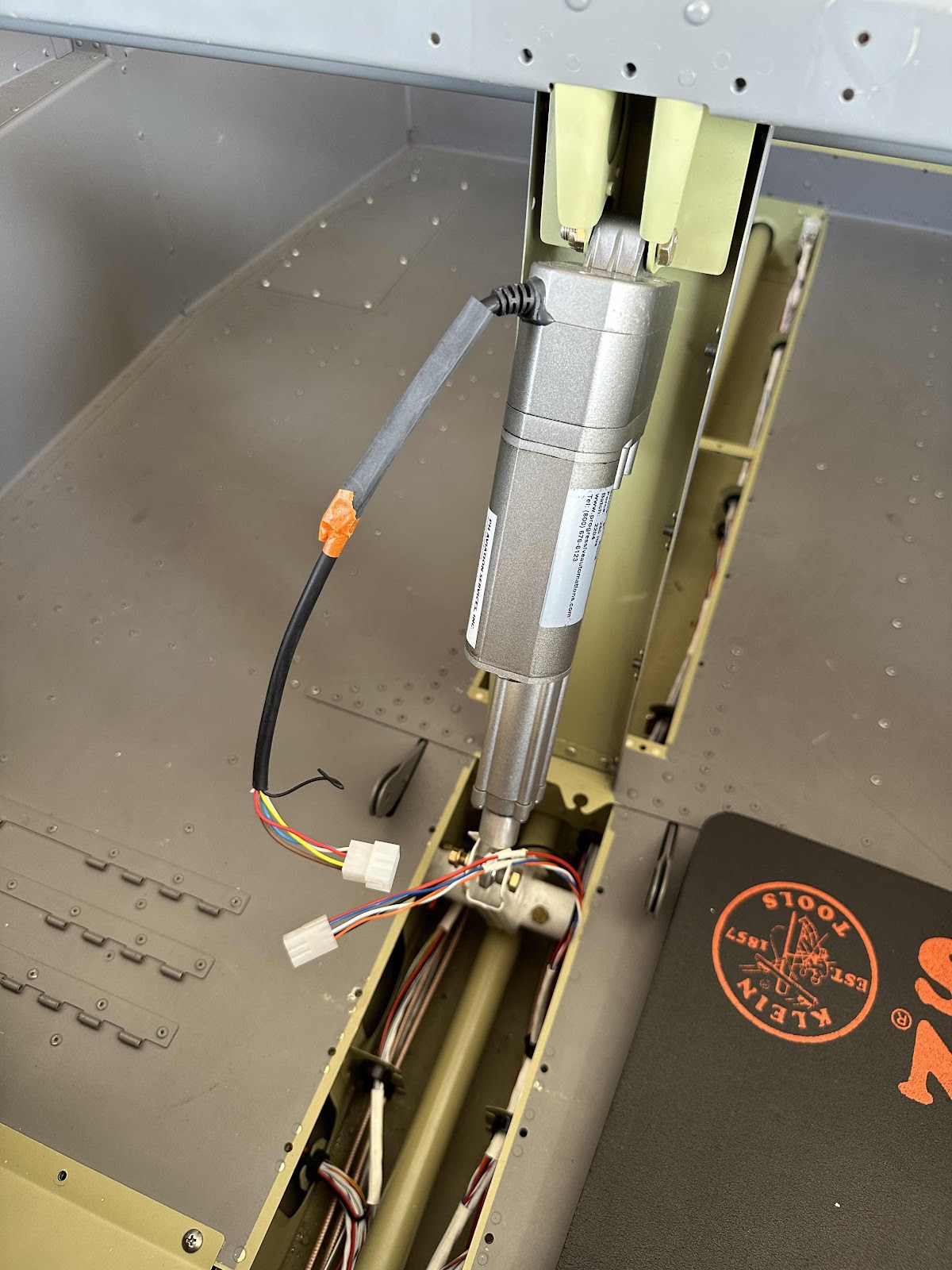
The next two pictures show the completed install of the actuator. I also secured the wire bundle to the flap motor channel with an adel clamp. I will need to make a “notch” on the flap motor front cover to clear the bolt head, as the “notch” from manufacturing is on the other side. (I installed the missing cotter pin and tightened the bottom nut, right after I took this picture).
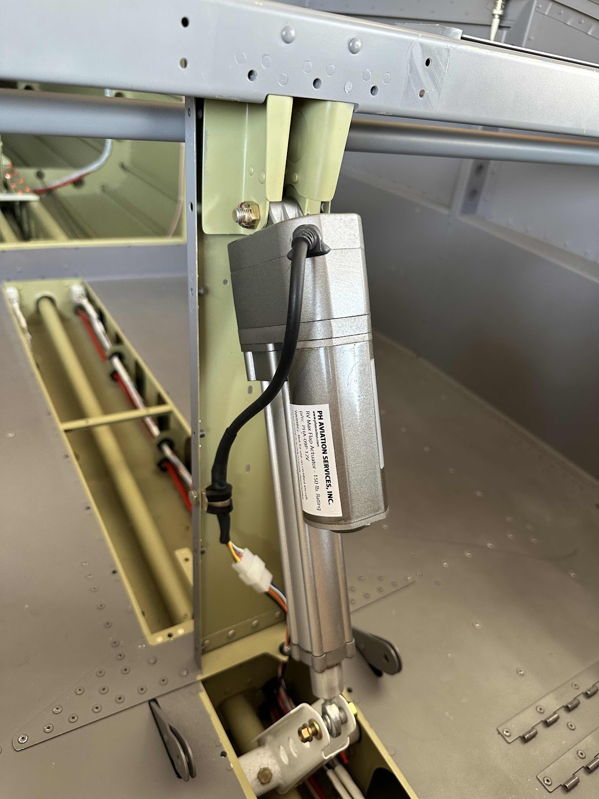
View of the actuator from the pilot side.

Install Complete