Showing posts with label Panel Installation. Show all posts

Monday, March 4, 2024

Panel Installation (Part 20) - JVL Aviation’s Transponder/Comm Bracket

The work and pictures in this post are from September 2, 2023.

Here is the transponder/comm bracket installed on the airplane (mostly).  I’m not going to final install it just yet…..I still need to do a little electrical work under the panel and don’t want the assembly in the way.  In this picture, I only need to install four washers and nuts to secure the assembly to the airplane…..two in the front on the glove box flange and two in the back on the firewall angle (in the two white circles).
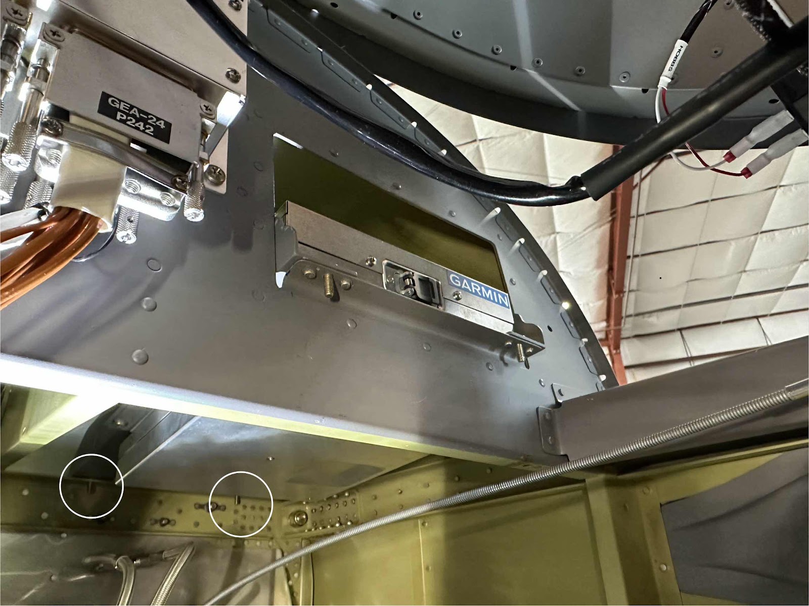
Here is another angle.  I used screws here in this picture, but have since decided to use AN3 bolts.  I always kind of looked at the glove box opening and thought to myself “why”?  Now, I’m not sure this is what Van’s had in mind for this opening when they designed the airplane, but it sure works pretty damn good for this install.  So, thank you Van’s for the adding this to the sub panel way back when!

This view is from the footwell looking up at the comm radio.  When I was making the bracket, I decided to leave about an inch of space between the radio and the sub panel.  I probably could have moved it back toward the sub panel more, but I saw no real reason to.  There is plenty of room to connect the radio’s harness at the rear, so this gap seemed to work out pretty well.


This is just another angle.  The cable you see in this picture is for co-pilot heat.  I just need to re-install the adel clamp right next to it in the nutplate.  I removed this clamp for a little easier access to the area under the panel when I was test fitting the bracket.


Well, other than installing it for good, that pretty much completes the “JVL Aviation’s Transponder/Comm Bracket”.  It took some time and a little trial and error to get it just how I wanted it, but I think it is a pretty good install.  I also bet the aluminum angles added a little extra strength to the sub panel in that area.  I’d like to think I made it a little better.
Panel Installation (Part 19) - JVL Aviation’s Transponder/Comm Bracket

The work and pictures in the post are from August 30, 2023.

Now, with the two “remote comm mounting plates” riveted to the angles, I can install the transponder tray (and transponder) to the angles.  Here are a couple pictures showing the final install.  In the first picture, you can see what is the top left side of the bracket.  It shows the transponder tray attached to the aluminum angles with the two screws and nuts, the transponder slide in and locked into the tray and the two mounting holes on the remote comm mounting plate for the comm radio.

This is the top right side of the bracket showing the same things.

Looking down from the top, you can see the shop heads of all of those 18 rivets, the four mounting holes on the two remote comm mounting plates and the four mounting holes for the glove box flange and firewall angle.

Here is another angle.

The comm radio is on the bottom of the bracket (just like it will be mounted in the plane).  I used four screws and nuts to complete the install.  This is the left side of bracket/assembly…..

……and this is the right side.  I’ll try to show it in the next post, but the pre-installed brackets on the comm radio are not flat and provide some “lift” to the radio.  This “lift” provides enough gap between the radio and the shop heads from the rivets I installed on the remote comm radio mounting plates.  During the fitting process, I actually had to squeeze a few of the outboard rivets a little more than normal to ensure they cleared the top of the radio and didn’t rub each other.

Finally, this bottom up angle shows the comm radio fully installed on the remote comm mounting plates.  If need be, there are two more locations I could add screws to on the remote comm mounting plates.


In the next post, we will mount the bracket/assembly in the plane.

Panel Installation (Part 18) - JVL Aviation’s Transponder/Comm Bracket

The work and pictures in this post are from August 25, 2023.

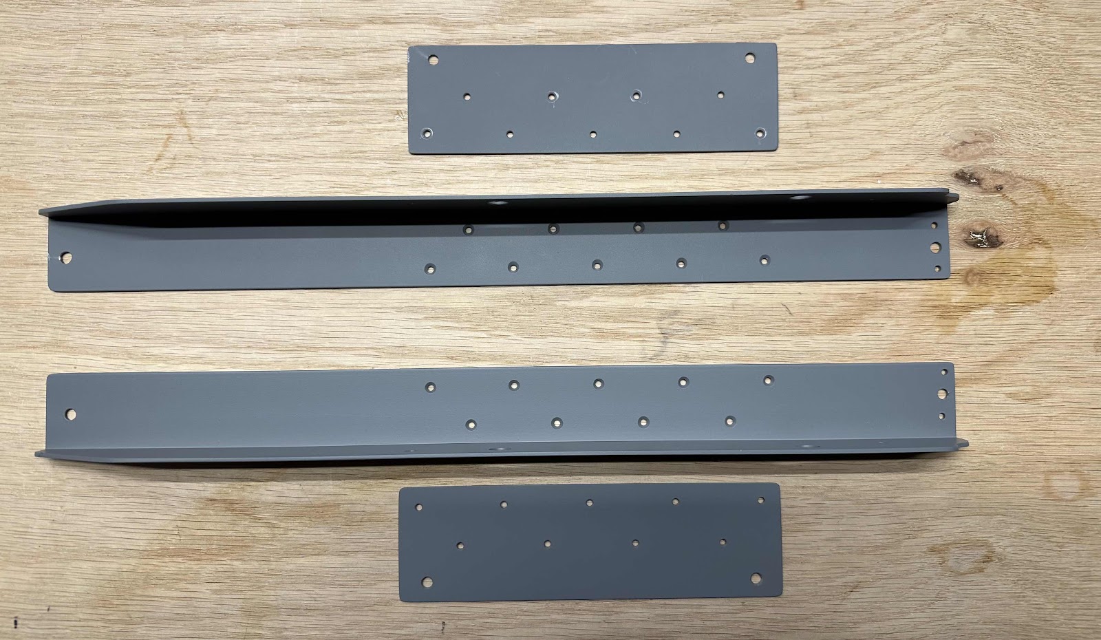
In the last post, I needed to come up with a mounting solution for the remote comm radio (GTR20) to the aluminum angles.  Well, here is what I came up with.  I made a couple of “remote comm radio mounting plates” to attach to the aluminum angles.  I match-drilled nine mounting holes for each plate and angle (not overkill at all - don’t judge me).  I used a rivet fan to lay out the holes and countersunk those holes on the upper side of the angles (where the transponder/tray will be attached).  Then, I drilled four mounting holes in the comm radio mounting plates corresponding with the slots on the mounting brackets pre-installed on the comm radio (those brackets came with the radio).  Lastly, I drilled four “lightening holes” in the angles (two on each angle).  I don’t know how effective they will be, but they look good.  Here’s a couple angles:


The next two pictures show the plates riveted to each of the aluminum angles and repainted….ready for installation.


Sunday, March 3, 2024

Panel Installation (Part 17) - JVL Aviation’s Transponder/Comm Bracket

The work and pictures from this post are from July 9, 2023

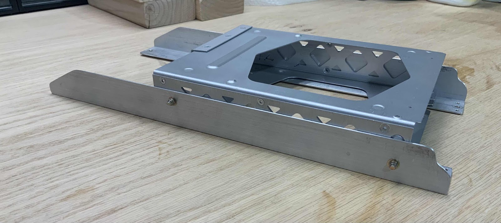
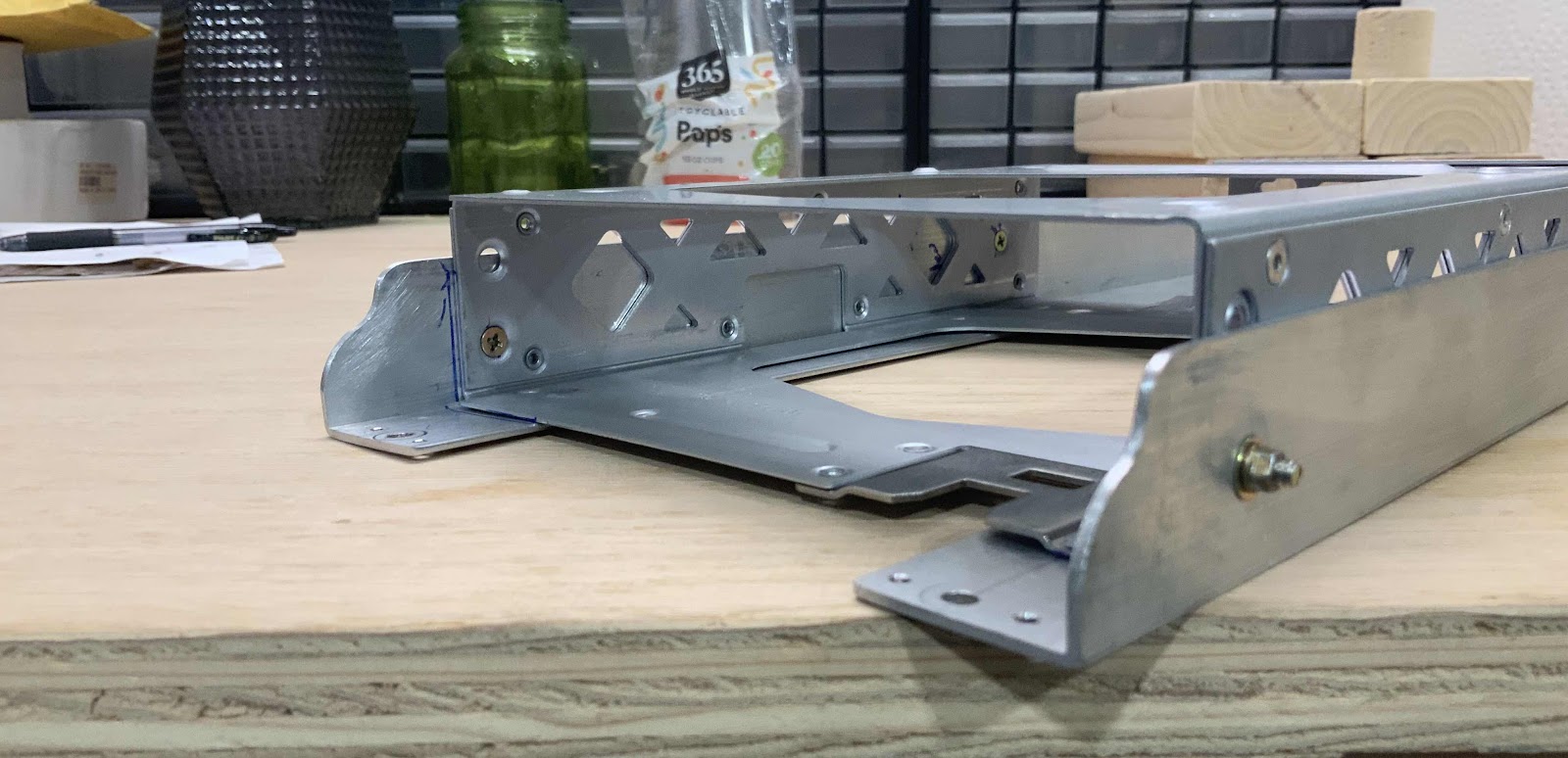
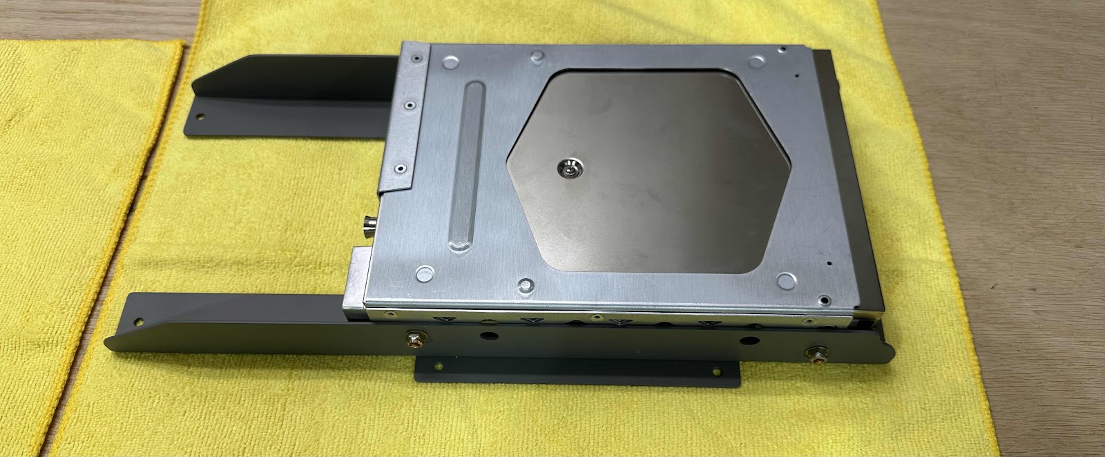
The four pictures below show several angles of the transponder tray attached to the aluminum angles.  Since the last post, I had to make another modification to the angles.  In the first picture below, on the left side of the angles, you can see I had to “round” those 90° corners as well.  I had to sand the angles to about a 45° angle in order to clear the bend in the upper forward skin.  It also cleans it up and looks more cosmetically pleasing (just like the front side). 

The tray already had six countersunk mounting holes (three on each side) built into the assembly on either side of the tray.  The front of the tray has an upper and lower mounting hole on the side(s) of the tray.  I used the lower hole because the upper hole was too upper for the aluminum angle…..easy decision.  The back of the tray only had a single mounting hole in the middle…..easier decision.  


So, with the transponder tray figured out and mounted, I need to figure out how to mount the remote comm radio to the bracket/assembly.  Here’s the comm radio sitting on the underside of the assembly (flipped over) where I intend to mount it.  The comm also has the side brackets (came with the radio) attached to the radio and they “stick” out the sides of the angles (same on the opposite angle).  I’ll figure out a mounting solution and show it in the next post.

Saturday, March 2, 2024

Panel Installation (Part 16) - JVL Aviation’s Transponder/Comm Bracket

The work and pictures from this post are from July 6, 2023.

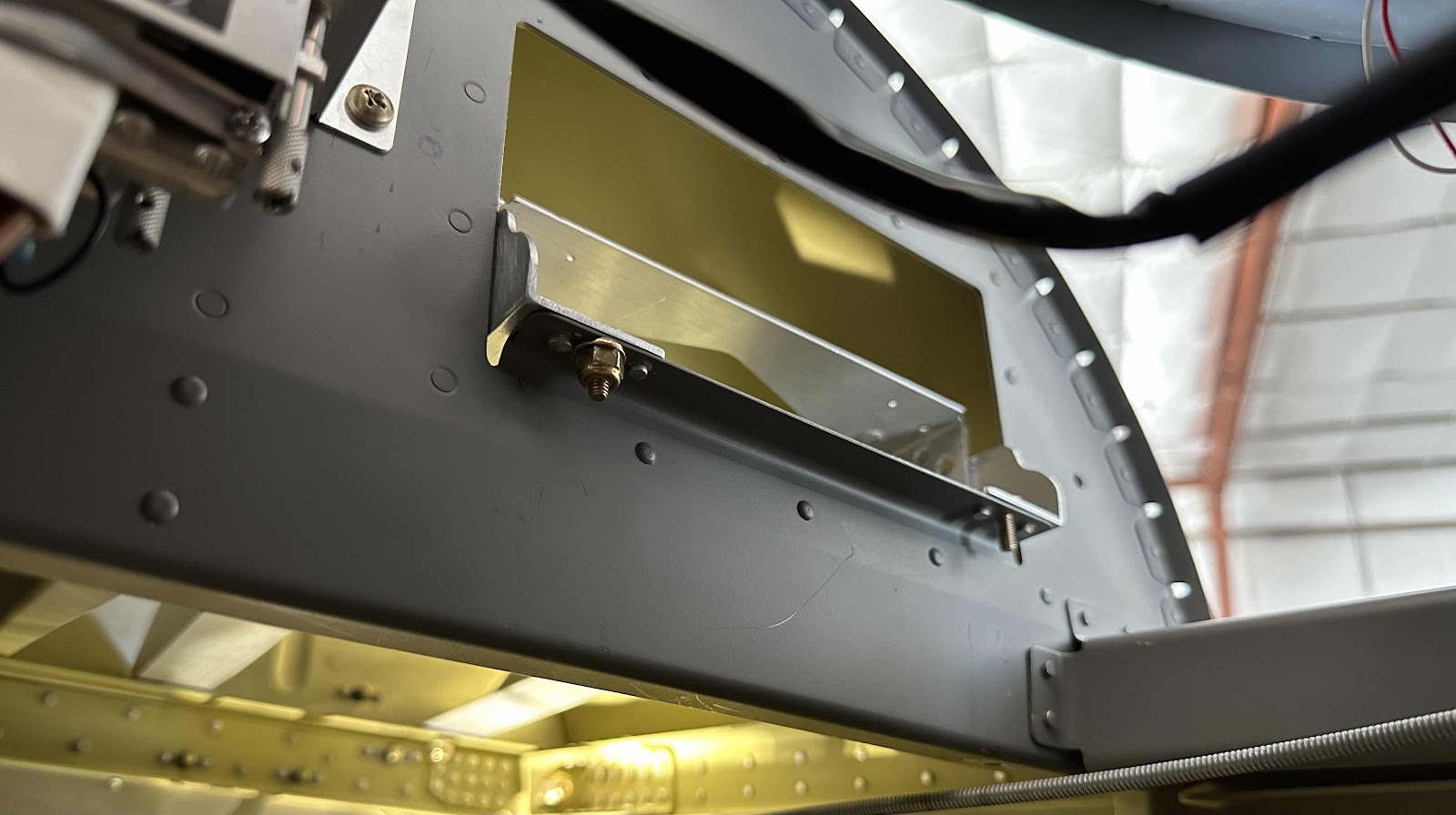
To start, I took some measurements from the “glove box” opening to the firewall angle.  Based on those measurements, I cut two pieces of aluminum angle from a stock piece of 1.25” x 1.25” x .063” to a length of 14.25 inches.  (I actually cut the angles slightly longer than 14.25” and sanded them to size…..which turned out to be 14.25”).  Next, I needed to verify the aluminum angle and the transponder mounting tray (all three pieces together) would fit in the glove box opening.  It was actually a perfect fit….go figure!   

To secure the bracket to the airplane, I match-drilled four mounting holes in the aluminum angles through the glove box “flange” and firewall angle…..two in the front and two in the back.  I used a 90° air drill to make all four of the holes.  The front two holes were pretty easy and straight forward, but the back two required a little more attention.  Not because they were overly difficult, but due to their location.  I had to use a couple of mirrors to make sure I was in the middle of aluminum angles and firewall angle.  Once everything was “centered”, I clamped everything into position and drilled the holes…..top down.  The 90° air drill was money in this situation.

I’m going to use AN3 bolts in all four locations to mount the bracket.  Here’s the glove box side with the two mounting holes completed (one bolt with a nut and one without).  Also of note in this picture:  I “rounded” the upper portion of the aluminum angles just as they exit the glove box opening.  That gets rid of the sharp 90° degree angles and make it cosmetically pleasing and a cleaner install.  I clamped the two angles and “rounded” them together, as one, so they would be the same…..worked out great!

Here are the two mounting holes in the back on the firewall angle.  Like I said, I had to use a couple different inspection mirrors to get this area correct.  One thing to pay attention to:  make sure the forward ends of the aluminum angles ARE NOT rubbing/touching the firewall.  The firewall angle is big/wide enough, I was able to leave about an 1/8” inch gap.  I think that will work great.


Working in this area was a pain in the butt.  Laying on your back, under the panel in the footwell, using air tools requiring air hoses, in a tight location!  It was definitely worth it in the end though…..just like most other things during the build.  I’m happy with the way this bracket is going to work out!

Thursday, February 29, 2024

Panel Installation (Part 15) - JVL Aviation’s Transponder/Comm Bracket

In the “Initial Panel Design” section (under Modifications and Upgrades), I talked about wanting to have a clean panel and one that didn’t look “busy”.  So, to accomplish that goal, I decided to get the GTR20 Remote Comm Radio for Comm 2 and the GTX45R Transponder (ADSB In & Out).  Both of these units are designed by Garmin to integrate with the G3X system and both are remote systems.  Now, with the decision made to use these two remote mounted avionics…..WHERE DO I INSTALL THEM?

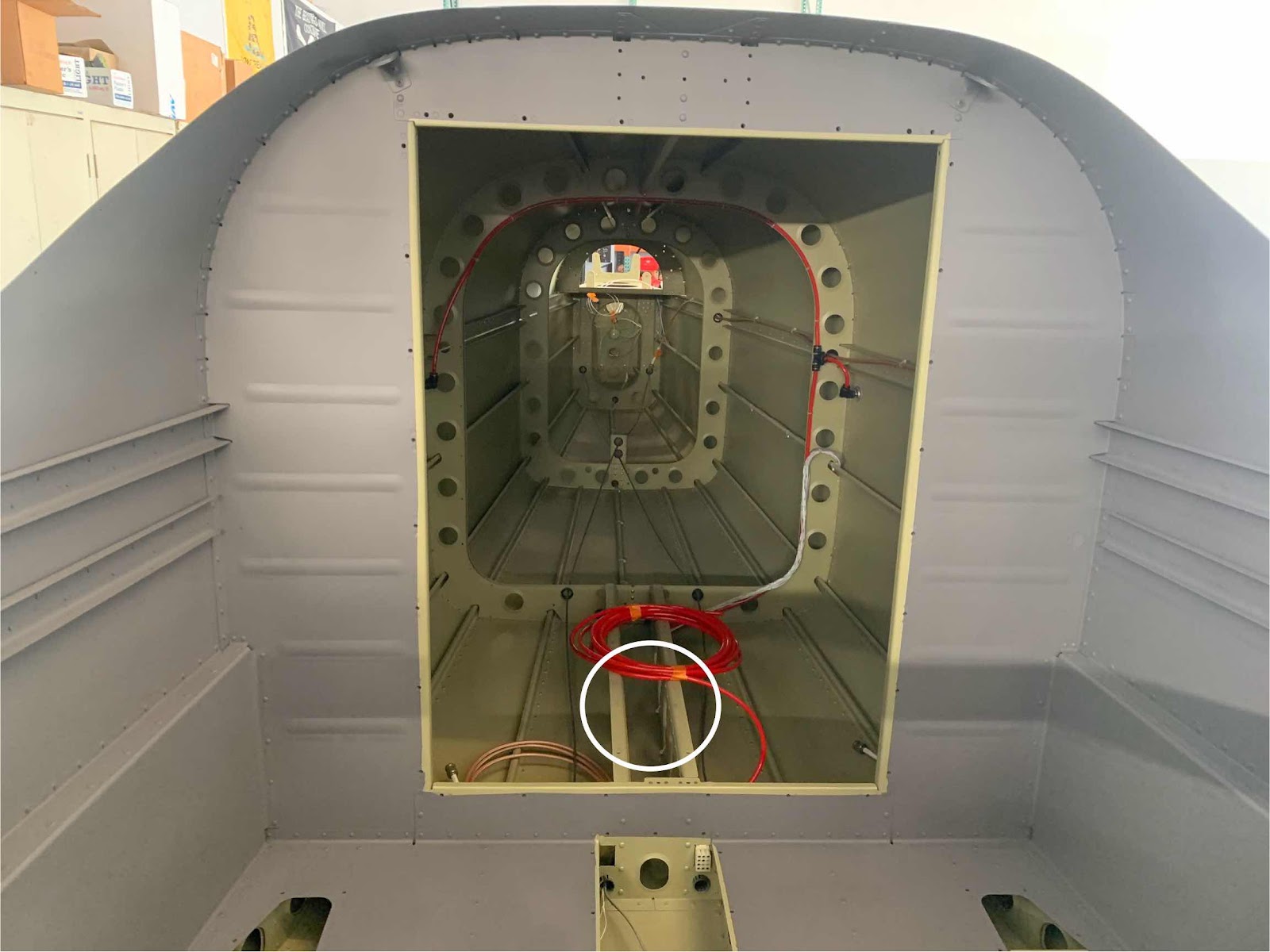
I initially thought about making some kinda plate or bracket and installing them in the tail section just behind the baggage bulkhead (shown below in the white circle).  I decided not to do that because of the distance from the panel.  I would have had to make (or have Aerotronics make) new harnesses to cover that distance.  Not the biggest deal in the world, but I didn’t want to do that.  Also, when Jason made the panel, he also included the harnesses for the GTR20 and GTX45R….already wired up and ready to go (just had to plug them into the back of each of those boxes).  Seemed like the easiest and most logical way to do it.

So, after some figuring, I decided to install them on the copilot side, in the “glove box” opening in the sub panel to the F-01401D Firewall Angle.  The next several posts will show what I came up with and how I made the bracket.

Saturday, February 24, 2024

Panel Installation (Part 14) - JVL Aviation’s Electrical Power Bracket

The pictures and work from this post are from January 6, 2024.

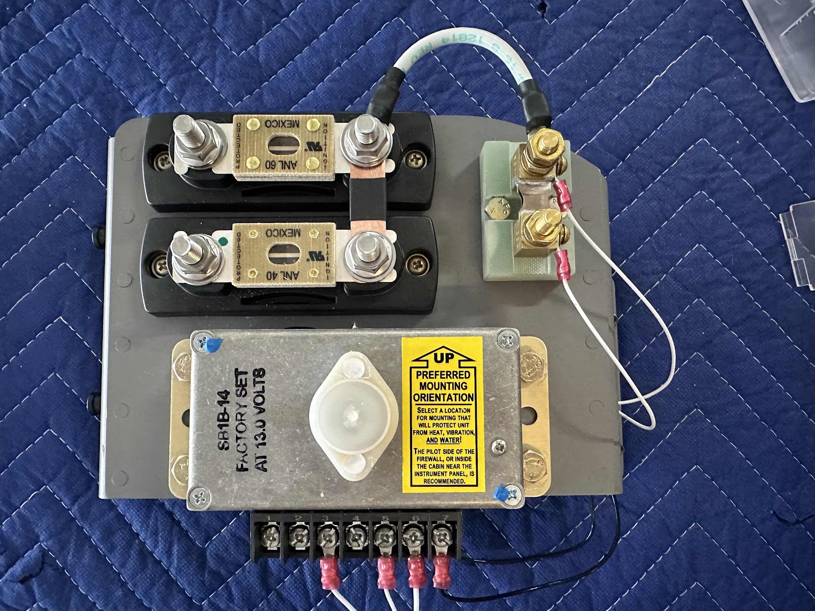
I completed the remaining electrical items (as it relates to the power bracket) in the pictures below (referencing my schematic drawing from the previous post):

-Fabricated/Installed the bridge wire from the top right post of the upper ANL limiter to the top post of the shunt
-Fabricated/Installed the copper bar between the right upper and lower posts of the ANL limiters
-Installed post #3, #5 and #6 on the standby alternator regulator

-Installed the amp shunt wire(s) from the GEA 24 through the grommet to the 1A circuit breakers
-Installed the proper sized adel clamp on the back of the bracket to hold the wires

- Installed the starter solenoid wire to the lower post on the shunt
- Installed the circuit breaker panel wire to the lower post on the shunt
- Installed the B-Lead from the main alternator to the left post on the upper ANL limiter
- Installed the B-Lead from the standby alternator to the left post on the lower ANL limiter
- Installed the 60 ANL fuse between the left and right posts on the upper ANL limiter
- Installed the 40 ANL fuse between the left and right posts on the lower ANL limiter

That pretty much covers the JVL Aviation’s Electrical Power Bracket.  There are a couple items I will address to call the installation truly complete.  
1.  I’m gong to turn the 40 ANL fuse the other way, so the opened end of the fuse is facing down (and won’t fall out if the nut gets loose????)
2.  Make sure I have adequate clearance between the wires on the far right and the skin of the airplane.  It doesn’t look it here, but there is about an inch of space between them in the picture 
3.  Install a boot for the wires on the lower post of the shunt (there is plastic covers that will be installed on the limiters)

Friday, February 23, 2024

Panel Installation (Part 13) - JVL Aviation’s Electrical Power Bracket

The work and pictures from this post are from January 3, 2024.

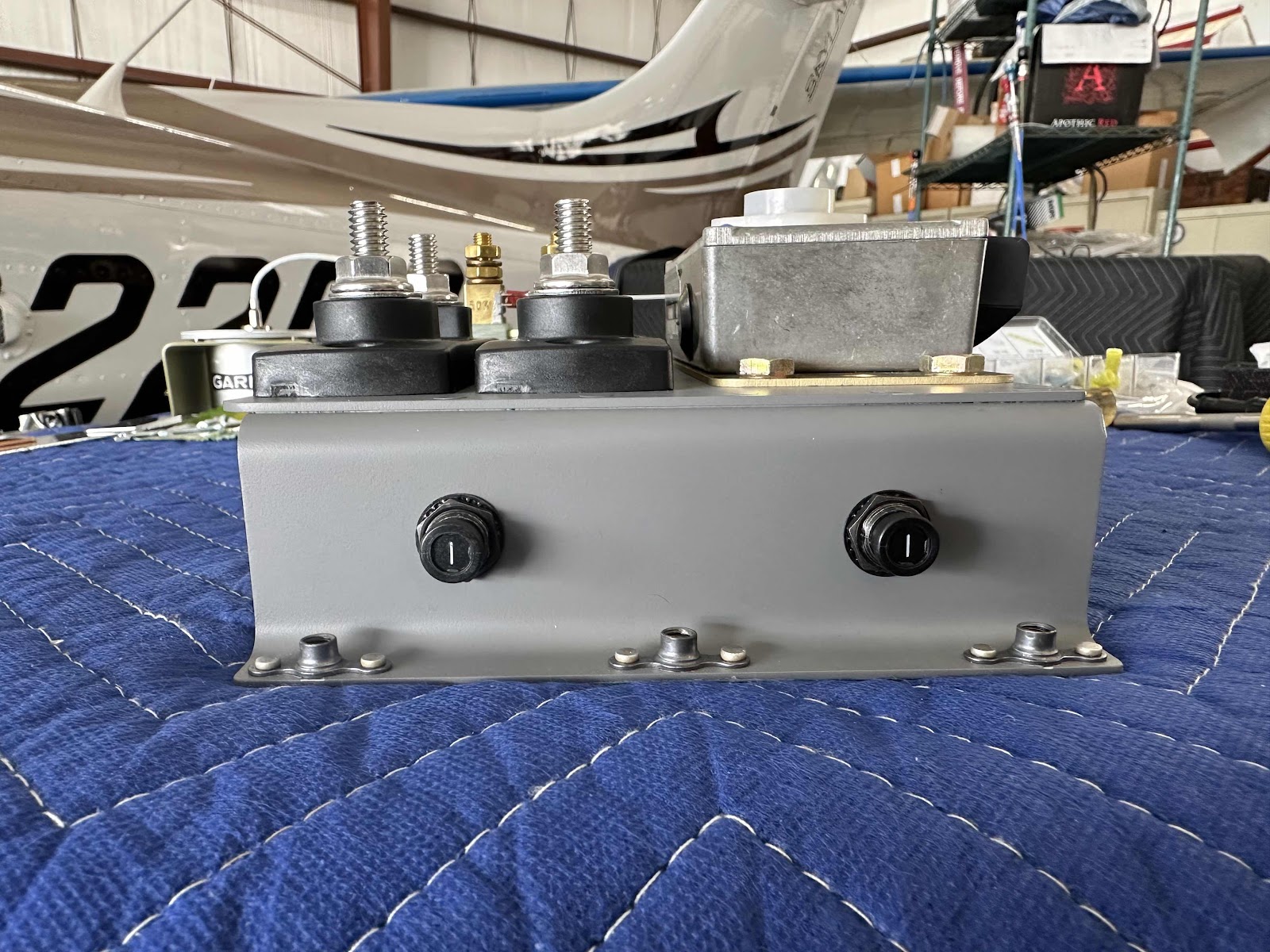
In the previous post, I mentioned the need for circuit protection for the wires coming from the shunt (as required by the electrical schematics from Aerotronics).  To comply with that requirement, I decided to use these 1A Circuit Breakers from Aircraft Spruce.  The two holes on the left side of the zees were actually the PERFECT size to accept the circuit breaker…..so, that’s where they went.

This view shows a couple of things:
- the two white wires attached to the shunt…..
- the two black ground wires attached to the standby alternator regulator (Post #7 and the case)


This is the opposite side of the bracket showing:
-the two white wires from the shunt attached to the 1A circuit breakers (through the rubber grommet)
-two black ground wires from the regulator attached to the ground post (I installed)

For the regulator ground(s) in the picture above, I ended up drilling a separate hole in the zee bracket to accomplish the grounding.  By doing this, the bracket could be removed by only removing the five mounting bolts…..and the ground(s) and associated wiring on the bracket would not interfere or have to be disconnected.  I thought it was the easiest way to do it instead of attaching it to one of the main bracket mounting bolts. 

On the flanges of the zees that will make contact with the sub panel, you can see I sanded a couple of spots.  I ultimately decided to sand the entire length of the flange(s) for grounding purposes.  Additionally, I sanded the backside of the sub panel (forward side actually) that the bracket will contact when it was mounted.  I used this Fine Sander Detail Kit from Aircraft Tool Supply Company to clean the mounting location on the sub panel.

Panel Installation (Part 12) - JVL Aviation’s Electrical Power Bracket

The work and picture from this post is from January 7, 2024.

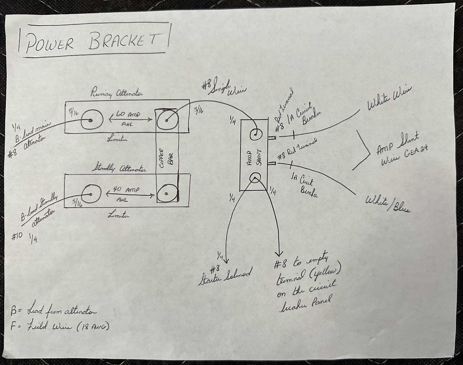
Back in Part 7, I discussed the decisions I made to get my electrical system “designed” and how/where I was going to mount all the parts and pieces.  Those decisions lead to the fabrication of the “JVL Aviation’s Electrical Power Bracket”, the location on the airplane the bracket was going to be mounted and what was going to be mounted on it.  Now, with all of those decisions and work completed, I needed to figure out how the actual electricity was going to flow between all the parts.  So, after LOTS of guidance and recommendations from Andre at Aerotronics, I drew this very simple schematic of how it was going to work on my plane:

Most of the drawing is pretty self explanatory (to me anyway), but I will explain some of my chicken scratch.  For example, on the top left (primary alternator):

B-lead main (alternator)
1/4:  size of the terminal on the alternator
#8:  gauge of the wire between the main alternator and the left post on the top ANL limiter
5/16:  size of the terminal on the left post on the top ANL limiter

On the bottom left (standby alternator):

B-lead standby (alternator)
1/4:  size of the terminal on the alternator
#10:  gauge of the wire between the standby alternator and the left post on the bottom ANL limiter
5/16:  size of the terminal on the left post on the bottom ANL limiter

The remainder of the drawing lays out the sizes of the terminals and gauges of the wires in the same fashion.  The professional wiring schematics I got from Aerotronics with my panel, also shows a 1A circuit breaker for each of the posts on the shunt (also shown in my drawing).  In a later post, I will show my solution for accomplishing that requirement.

I mentioned at the top of this post about the guidance and suggestions I got from Andre at Aerotronics.  I’ve said it before and I’ll say it again…..Jason and Andre have been a wealth of information and knowledge…..I can’t recommend their services enough.  I literally spent hours on the phone with Andre (over many separate phone calls) asking his advice and getting direction on best and safe practices.  They are some great dudes!

*****DISCLAIMER*****

The electrical schematic and system shown on this post, and in my entire blog, are my own design and applies only to my airplane.  If this information helps you, great.  But, please do your own research and seek guidance from professionals when designing the electrical system for your own airplane.  

Panel Installation (Part 11) - JVL Aviation’s Electrical Power Bracket

The work and pictures from this post are from September 3, 2023.

Now that the bracket has been completely trimmed and formed to fit the plane, I repainted it and attached the six K1000-3 nutplates using AN426AD3-3.5 rivets (the same hardware used on the fuel tanks in Section 18).  Here is the front side…..

…..and underneath.

The 1/8” of material I trimmed off the zee flanges leaves enough space for the nutplates to sit on and the appropriate edge distance for the rivets.


Now, I installed all four of the parts onto the completed bracket with the hardware described in Part 8.  Here are a couple of angles:


I got a little happy with the torque seal and put it on the nuts underneath after everything was mounted.  It’s kinda like Frank’s Hot Sauce, “I put that S**** on everything”!

Finally, here is the initial “mounting” onto the airplane using AN3-4A bolts.  I didn’t show it, but prior to installing the nutplates on the zee brackets, I match-drilled the five mounting holes into the sub panel.  I marked the five holes and used a 90° air drill to make the holes (from forward to aft…..there was not enough room with the avionics to go the other way…..mostly).  It also made more sense to match-drill the holes from the side the bracket would be mounted on.

This is looking at the opposite side of the sub panel (looking forward).  From this angle you can see the five AN3 bolts I used to mount the bracket to the sub panel.  

Panel Installation (Part 10) - JVL Aviation’s Electrical Power Bracket

The work and pictures from this post are from September 2, 2023.

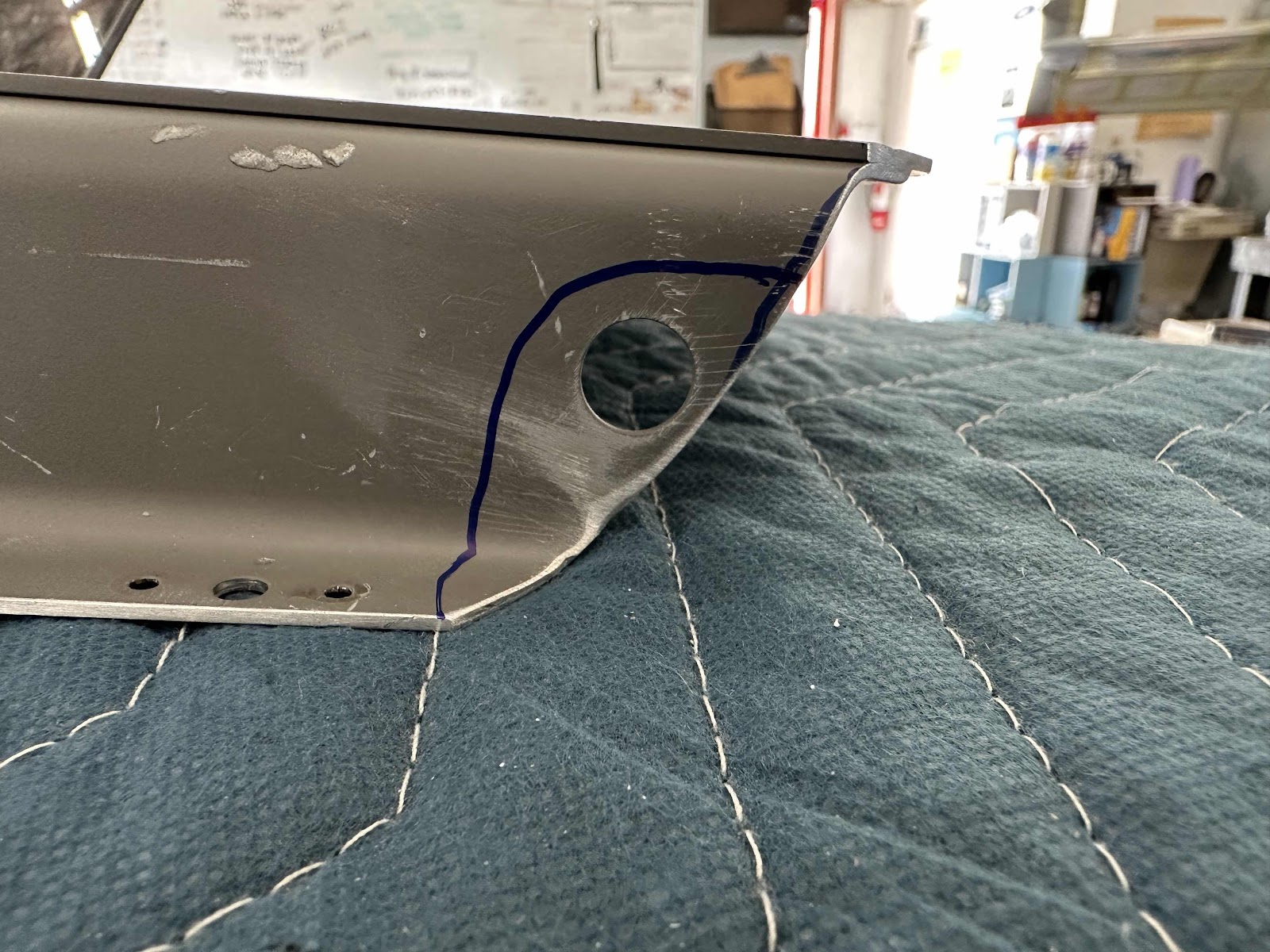
After trimming the bracket, I wanted to form the upper right edge and make it look better.  The upper hole in the flange of the zee looked really weird after I trimmed the material away.  Especially, that narrow little strip of material between the edge I cut and the side of the hole.  In the first picture, I marked with a sharpie my initial thought to remove material around the hole.

Then, I thought why?  Why not use the radius of the hole…..to remove the hole?  (The inner sharpie mark).

This picture shows the material removed along the hole’s radius.

To finish up, I removed all the paint previously applied to the bracket (however, the Alodine is still on the bracket).  Then, I sanded all the formed edges and zee flanges until they were complete and how I wanted them.  Here is the completed upper right corner of the bracket…..

…..looking straight down…..

…..from underneath (with the nutplate rivet holes countersunk)…..

…..and the left edge.

Monday, February 19, 2024

Panel Installation (Part 9) - JVL Aviation’s Electrical Power Bracket

The work and pictures from this post are from September 2, 2023.

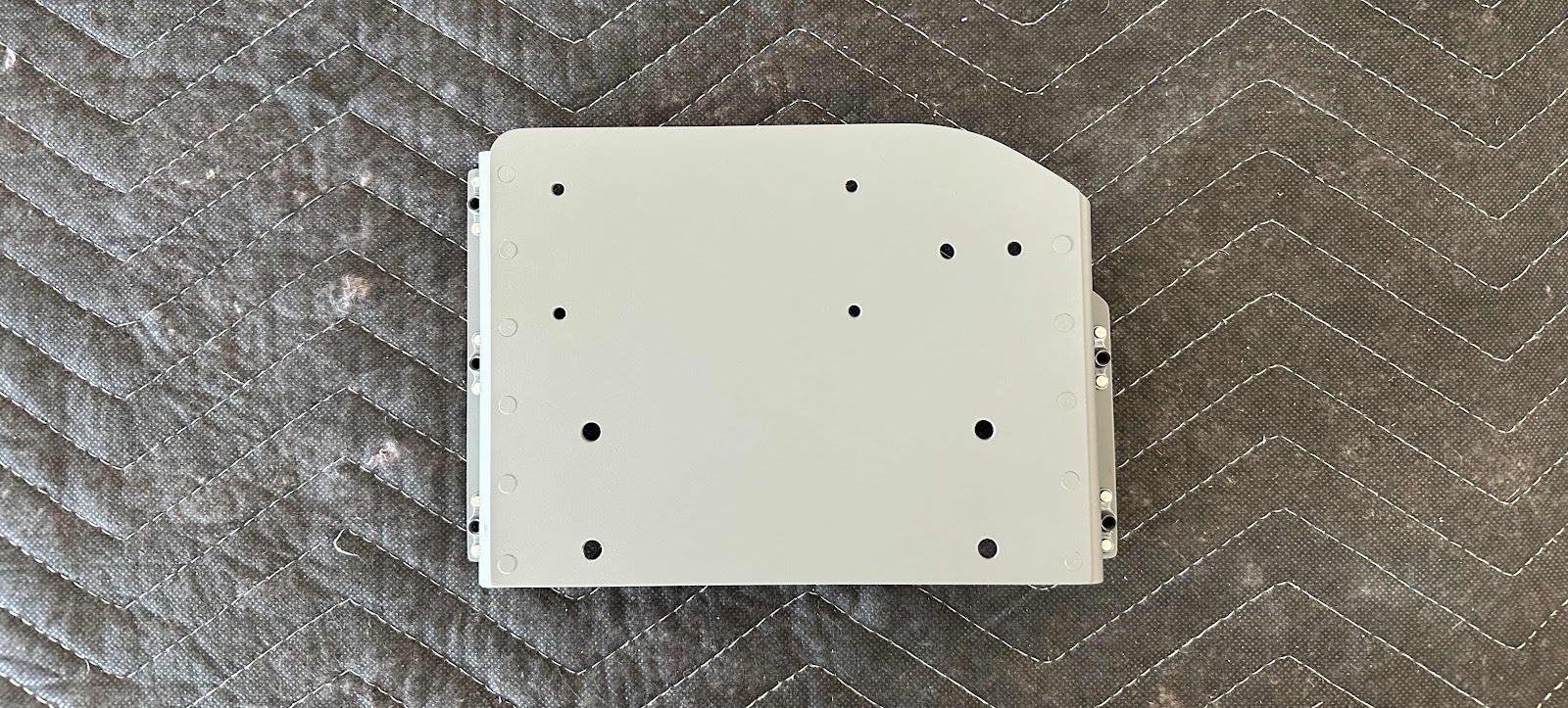
As I mentioned in the previous post, the bracket had to be MODIFIED again.  Once I finished making the bracket, I did a test fit in the location I wanted to mount it in the plane on the sub panel.  Come to find out, it was just a “smidge” (technical term) too wide.  So, I had to trim off about 1/8” of material from each tank zee.  I used my die grinder with a cutoff wheel to trim the material and then sanded the edges with 220 grit sandpaper and a sanding block.

There is just enough material to rivet the nutplates to the tank zees.  (Pictures of that in the next post).


Because of the bend in the F-01471 Forward Top Skin, a small portion of the upper right hand corner also had to be removed.  Again, I used my grinder and cutoff wheel to trim this area. The two pictures below show the results.

This is after a little bit of sanding to remove the sharp burrs.