Showing posts with label Section 17-Outboard Leading Edge. Show all posts

Friday, June 11, 2021

Wings, Outboard Leading Edge (Part 35)

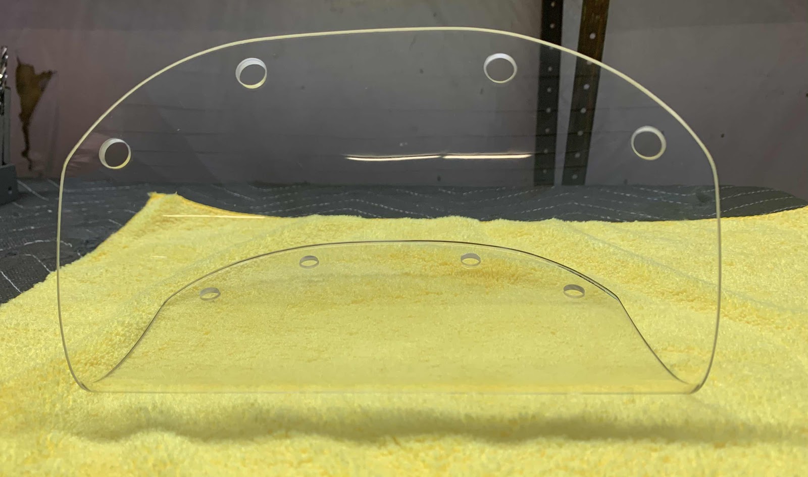
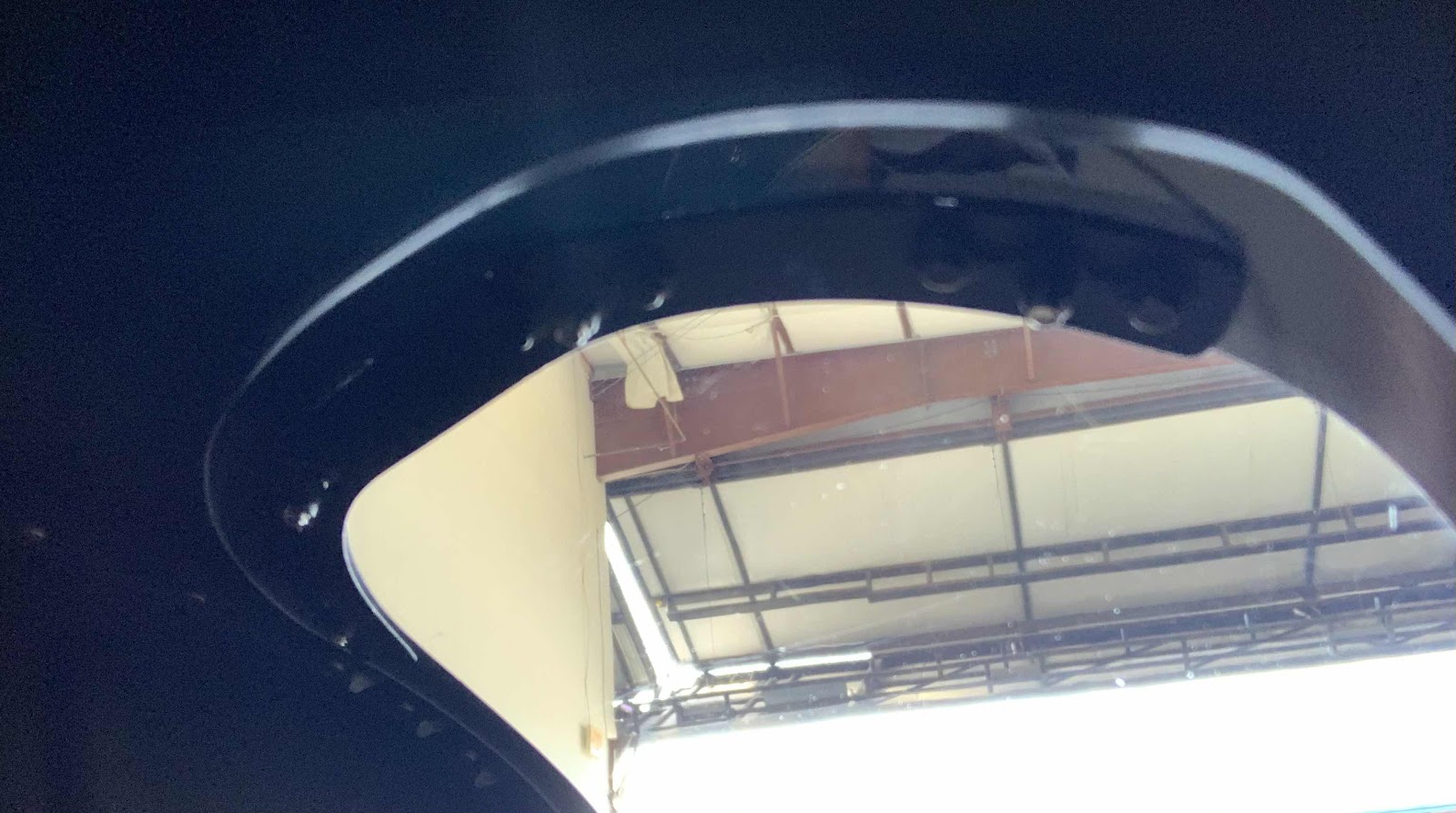
In Part 34, the right Lens was installed in the “pre-punched” landing light opening in the right Wing.  During this work session, I installed the Lens in the same opening on the left Wing.  I used the same method as discussed in Part 34.....and here is the result.  After completing all the required trimming of the Lens, these are the attach holes stepped to 5/16” with a step bit.  As in Part 34, I made the holes this large to completely surround (but not touch) the dimpled holes in the wing skin in an attempt to help prevent the Lens from cracking.


The holes in the Wing Skin were dimpled to accept the AN507C632R6 attach screws and the Lens was installed in the Wing.

Here are a couple pictures of the upper and lower W-00018 Backing Plates.  This is the lower plate.....

.....and the upper plate.
Section Complete
Saturday, October 10, 2020

Wings, Outboard Leading Edge (Part 34)

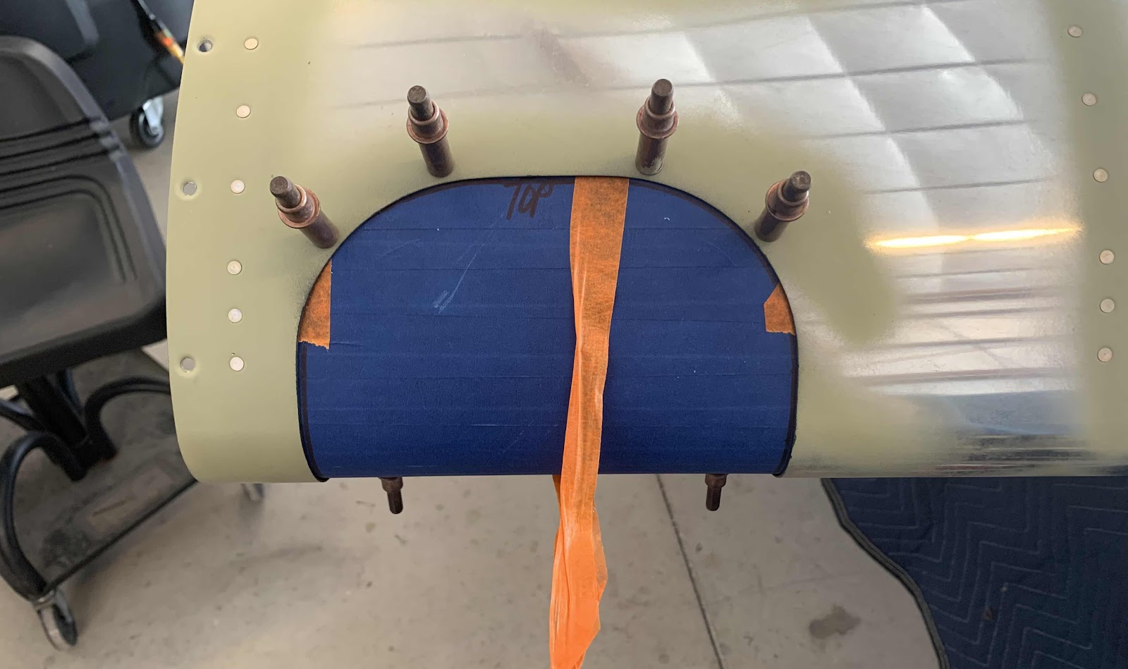
In this session, we will install the Lens on the wing (again, we are only doing the right Wing for now).  To start, we aligned the Lens in the opening using the lines we previous drew on the tape and used the “orange tape handle” to pull it tight against the inside of the Wing.  The plans says to use plexiglass drill bits to drill holes in.....wait for it, plexiglass.  My A&P buddy (who has been helping and guiding me through out the build) said he recommended using a unibit to drill holes in plexiglass.  So, that’s what I did.  The first step on my unibit is 1/8”, so very close to a #30.  After each hole was match-drilled (very carefully), we inserted a cleco.  Here is the four holes on the top.....

.....and the four holes on the bottom.

Now, for some figuring.  The plans say to enlarge the #30 holes (1/8” in my case) we just drilled to #27 and countersink them to accept the dimples for the #6 screws on the Wing Skin.  First of all, my unibit doesn’t have a #27 step and I’m scared to countersink the plexiglass.  I don’t feel like I can countersink all the holes accurately enough not to introduce cracks (now or later).  So, I asked my buddy Jeff.  He recommended making the holes large enough to encompass the whole dimple on the Skin.  This way, all the holes will be the same, there will be no stress points on the plexiglass created by imperfect countersinks, and the Lens will sit flush on the inside of the Skin all the way around.  SOLD!

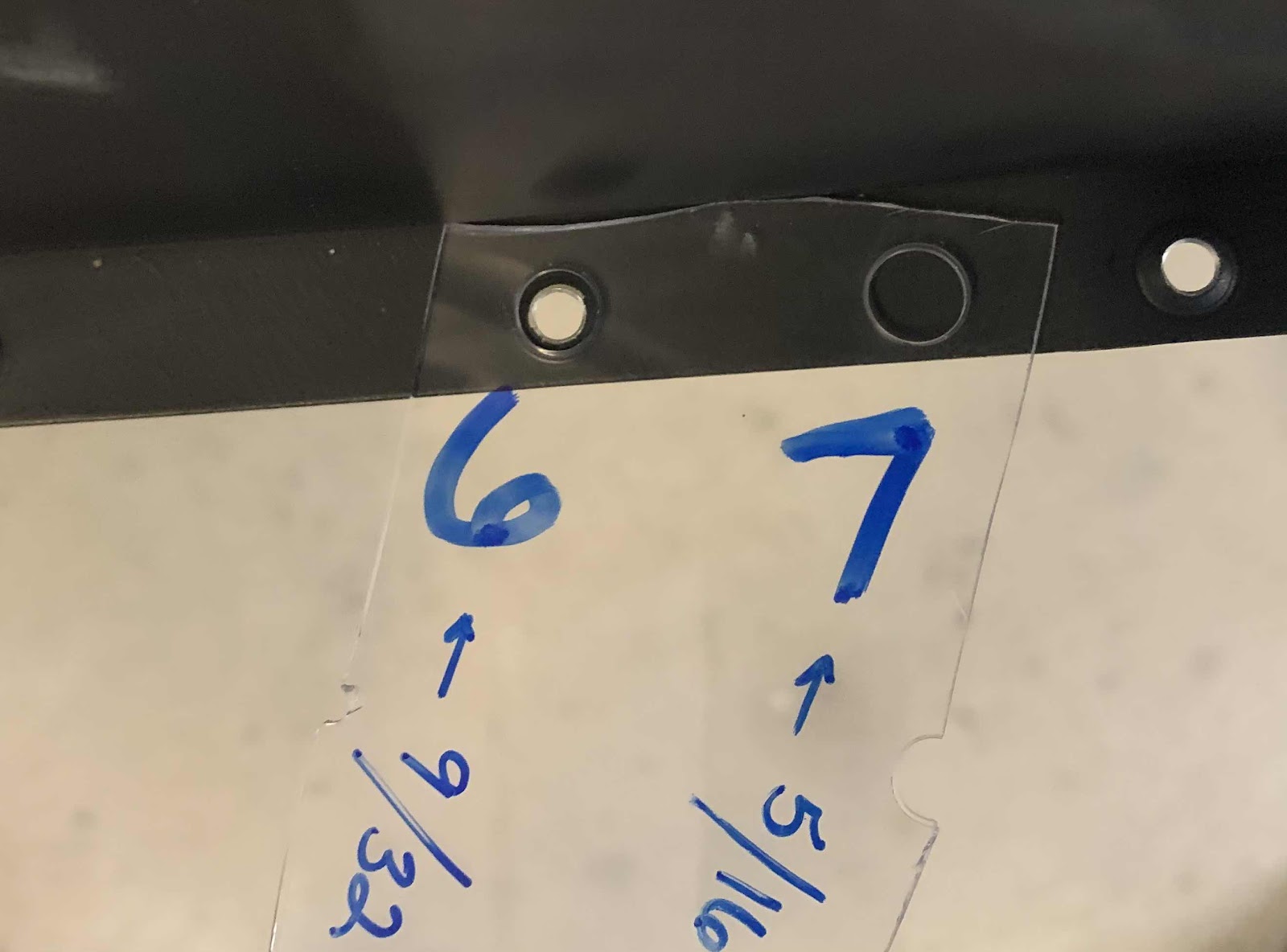
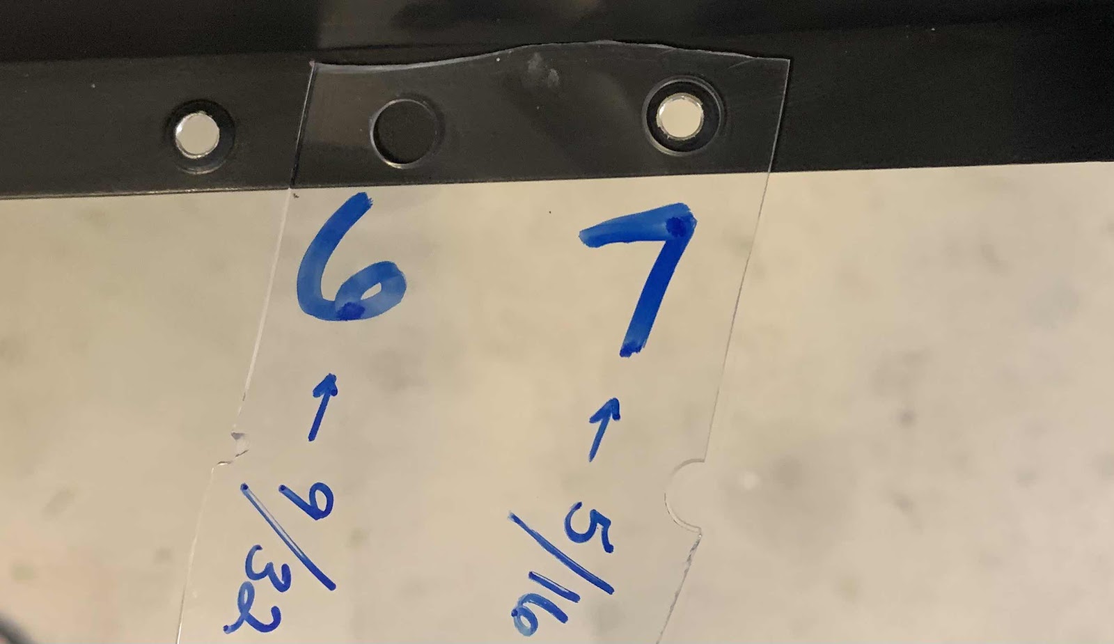
The two holes sizes came down to step #6 (9/32”) and step #7 (5/16”).....this my test piece and jig.

The #6 step was slightly too small and did not completely encompass the dimple or sit flush on the Skin.

The #7 step fit perfectly around the dimpled hole and sat completely flush on the Wing Skin.  So, #7 it is!


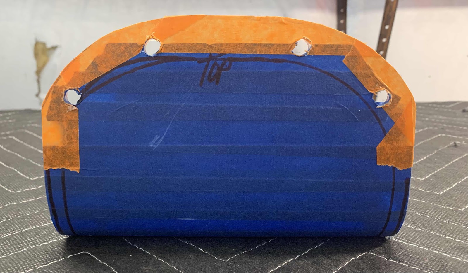
After bracing the Lens on the corner of the table, here are the four holes cut to the #7 step on the top.....

.....and the bottom.

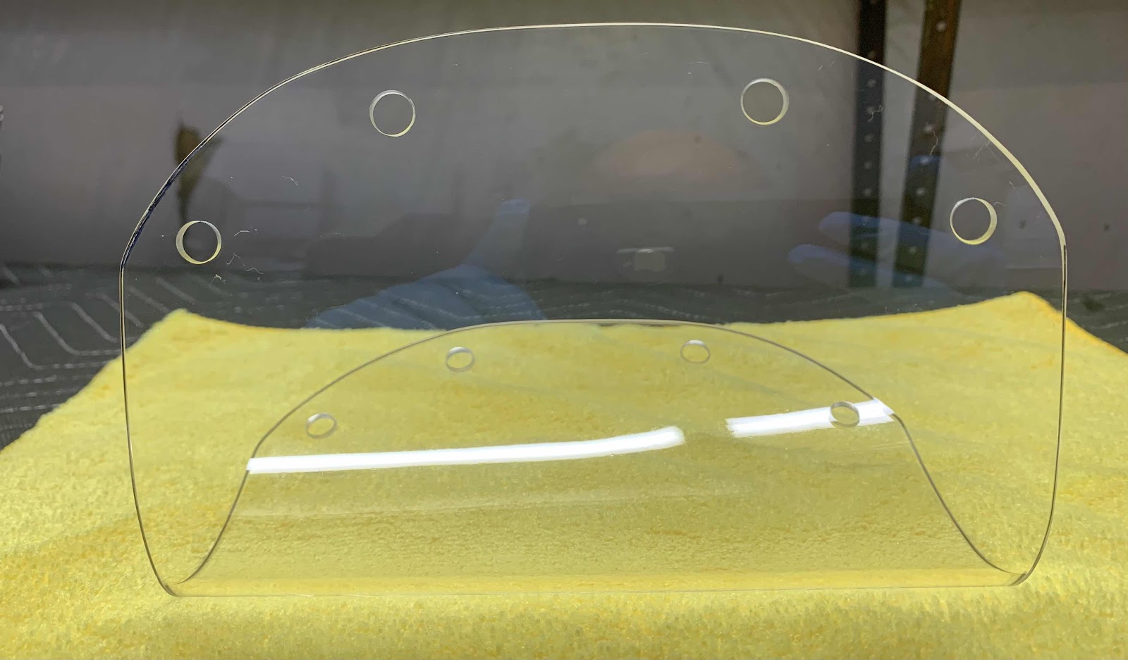
After removing the tape, here is what the holes looked like....all the same sized holes and no cracks.


Lastly, we installed the Lens on the Wing using the two backing plates shown in Part 33.  Here’s the completed install showing the top.....

.....and the bottom.

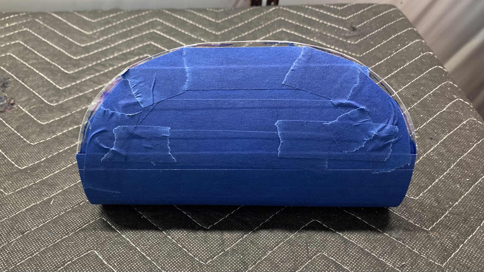
Once completed, we covered the Lens with a microfiber cloth to keep dust and debris off and help prevent scratches.  Turned out pretty good I think.  We will use the same method to complete the Lens for the left Wing in a later session.

Thursday, October 8, 2020

Wings, Outboard Leading Edge (Part 33)

This work session was nothing more than sanding the edges of the Lens to the desired shape.  After sanding, checking, sanding, checking, etc.....

Here is the final shape of the bottom portion of the Lens.....

.....and the top portion.  I am pretty please with the results.  In the next session, we will install the Lens on the Wing.

Wednesday, October 7, 2020

Wings, Outboard Leading Edge (Part 32)

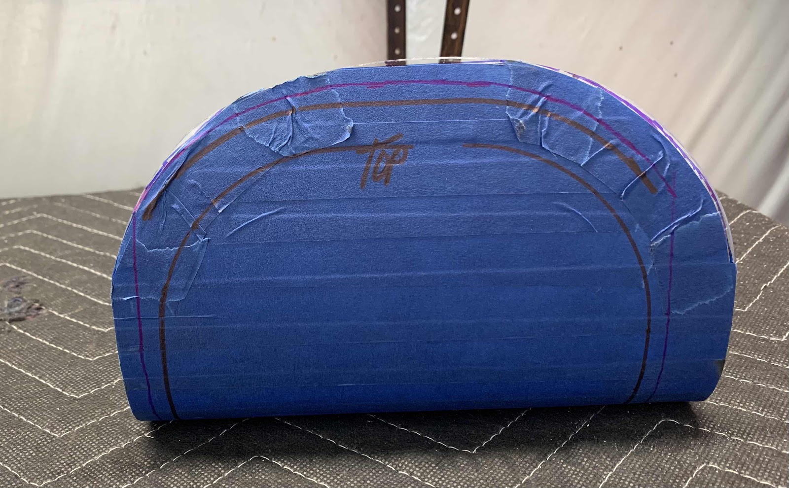
Seems like so long ago since we completed Parts 30 and 31.....May 17-18, 2018.  Fast forward about 2 1/2 years and we’re back.....for the landing light Lenses.  The first step was to place the Lens on the Leading Edge and mark a line approximately 3/4” [19.0 mm].  I used a ruler and made many little marks at 3/4” and then free handed the marks to make the line you see in the pictures below.   This step is mostly necessary to remove a large portion of the edges so the Lens will fit into the opening in the Leading Edge.  This is the top.....

.....and the bottom.

The areas “outside the lines” marked above was then removed.  However, prior to completing this step, I covered the Lens with tape to protect it from damage.  I then used a belt sander to remove the material.....slightly short of the lines marked above.  Here is one side.....

.....and the other.

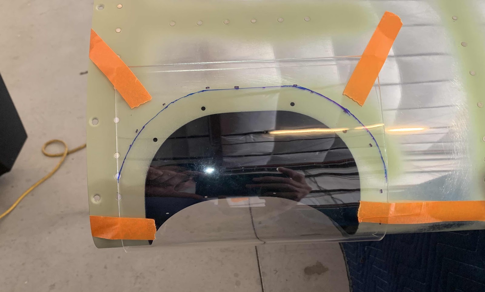
Once the appropriate amount of material was removed, it fit easily into the landing light opening on the leading edge of the Wing.  The plans instruct you to use tape to make a “handle” to pull the Len snug against the inside of the Wing.  If your working by yourself, this actually worked pretty well.  If you have a helper, they can easily reach into the end of the wing and press it forward.  Once pulled or pressed agains the inside of the Wing, the opening in the leading edge was traced onto the Lens.  (Another good reason to tape the Lens so you don’t draw directly on the Lens).

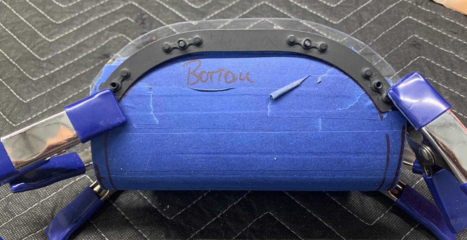
Next, the W-0018 Backing Plates (prepared in Part 16) were clamped to the Lens as shown below.  Then, a line was traced on the Lens along the upper end  (or aft end) of the Plates.

Lastly, a final line was marked at 1/4” [6.3 mm] above the line created with the Backing Plates.  This is the smaller blue line at the top.  Here is the top (which actually looks a little skinny on the top left and right edges....I’ll confirm prior to sanding).....

.....and the bottom.

I’ll pick it up here during the next work session.

Friday, May 18, 2018

Wings, Outboard Leading Edge (Part 31)

As I mentioned in my previous post, the last remaining steps in Section 17 is the installation of the Landing Light Lenses.  I have decided to wait on that for the moment.  I feel like I need to do a little more research before I’m comfortable working with the plexiglass (trimming, drilling, etc).

So, I’ll update this section when I start the installation.

Thursday, May 17, 2018

Wings, Outboard Leading Edge (Part 30)

Today, we started off by modifying the Wing cradle we built yesterday.  The problem was that the portion of the cradle that the Spar rests on was way to high, which resulted in a fairly significant lean of the Spar.  So, we took that section of the cradle apart, cut off 3 inches, and reassembled it.  It’s much more level now (we should have taken 4 inches, but I’ll live with the way it is now.  In the pictures below, you can see a more level appearance.

With that little bit of business complete, we moved on to riveting the Outboard Leading Edge to the Right Wing.  I didn’t take any pictures of this side because it looks just like the Left Wing.  We started by installing the rivets (LP4-3 and LP4-4) in the Wing Ribs, Main Spar, and Leading Edge Ribs.  Next, we installed the rivets in the Upper Leading Edge to the Main Spar and then to the Lower Leading Edge to the Main Spar.

The picture below shows the Right Wing in the cradle with all the rivets installed in the Outboard Leading Edge.

Here are the Left and Right Wings resting in the cradle.

The picture below shows the Left Wing in the cradle with all the rivets installed in the Outboard Leading Edge.

The final step to complete Section 17 in the plans is to install the Landing Light Lenses.  I’ll need to study the plans to see if now is the right time to complete this step OR should we wait until after the Landing Lights are installed.  More on this in the next post.  



*****176 Rivets Installed*****

Wednesday, May 16, 2018

Wings, Outboard Leading Edge (Part 29)

Today was a BIG day in Section 17.....we joined (riveted) the Left Outboard Leading Edge to the Left Main Spar.  The 63 rivets for the top are located just above the black line in the picture below.

The 62 rivets on the bottom are located just above the black line in the picture below.  (One of the rivets locations will be used for the installation of the pitot tube at some point in the future, which is why there is only 62 rivets on the bottom and not 63 like on the top).  Additionally, the six Wing Ribs seen below (and area in the black circle) had to be blind riveted to the Main Spar AND the Ribs in the Leading Edge.  The three Wing Ribs on the right used LP4-3 rivets and the three Wing Ribs on the left used LP4-4 rivets.  The area in the black circle below used universal AN470AD4-5 rivets.

Here is the front (or top) of the Left Wing in the wing cradle with all the rivets installed in the Outboard Leading Edge.....

.....and the back (or bottom) of the Left Wing with all the rivets installed in the Outboard Leading Edge.

I will have to make a few adjustments to the Wing cradle tomorrow to level out the Main Spar.  Otherwise, the cradles are working great.  We will attach (rivet) the Right Outboard Leading Edge to the Right Main Spar tomorrow.


*****173 Rivets Installed*****

Tuesday, May 15, 2018

Wings, Outboard Leading Edge (Part 28)

After completing Section 16 (Top Wing Skins), we went back to the Outboard Leading Edges.  We started by assembling 
the Stall Warning Subassembly as shown in the plans excerpt below.....

Once assembled, it was installed on the W-1008-R Spice Rib as shown in the plans excerpt below.....

The picture below shows the Stall Warning Vane extending from the slot I previous made in the Left Outboard Leading Edge Skin (Part 7).

This is the inside bay of the wing that houses the Stall Warning Subassembly.  In the picture below, it is installed to the Splice Rib with two 832 x 1/2 screws.

The next step was to Final-Drill .375 the hole for the tie-down on the bottom of both Leading Edge Skins.  This hole was pre-punched by Van’s to #40 and had to be enlarged to 3/8 to allow the tie-down ring to be inserted through the Skin.  After I initially enlarged the hole to 3/8 (Left Wing shown below), it was “slightly” off centered.  So, after some filing and sanding, I got the result pictured below.  I also cut the 3/8 hole in the Right Wing, but I will make any final alignments required when it gets clecoed the the Right Main Spar for riveting. 


Now for the fun part.....preparing to install the Outboard Leading Edges to the Main Wing Spars!  Pictured below is the overall view of the Left Wing with the Outboard Leading Edge clecoed into place. 

Here is a little closer view.

Tomorrow, we will start riveting the two assemblies together.

Sunday, May 13, 2018

Wings, Outboard Leading Edge (Part 27)

During today’s session, we also riveted the J-Stiffeners in both Outboard Leading Edges.  Each J-Stiffener received 62 rivets.  Below is a picture of the Left Outboard Leading Edge with the J-Stiffener riveted into place (horizontal row across the top).

This is the inside of the same Leading Edge and you can also see the J-Stiffener riveted into place.  As I mentioned in a previous post, the portion of the J-Stiffner in the Landing Light was painted flat black....the remainder of the J-Stiffener is in Akzo green. 


*****125 Rivets Installed*****

Friday, May 11, 2018

Wings, Outboard Leading Edge (Part 26)

As I mentioned in the last Outboard Leading Edge Post (Part 25), the J-Stiffeners needed to be prepared prior to installation.  During today’s session, the J-Stiffeners were treated with Alumiprep, Alodine, and Akzo Primer.  The picture below show the two Stiffeners drying after being primed.

Pictured below in the Right Outboard Leading Edge with the primed J-Stiffener clecoed into place.  I also painted flat black the section of the J-Stiffener that extends into the Landing Light Bay.  The Left Outboard Leading Edge was prepared in the same fashion. 

The two J-Stiffeners (one for the Right Outboard Leading Edge Skin and one for the Left Outboard Leading Edge Skin) will be riveted into place tomorrow.

Thursday, May 10, 2018

Wings, Outboard Leading Edge (Part 25)

We finished riveting the Right Outboard Leading Edge Skin (again, minus the J-Channel) during today’s session. 

Another view of the inside Ribs with the J-Channel clecoed into place.

Like I said yesterday, this is a cool shot!  Additionally, the aluminum J-Channel you see clecoed here will also have to be painted flat black to match the Landing Light Bay.  I will do this after it gets primed.

Below are the completed Left and Right Outboard Leading Edge Skins awaiting the J-Channels (the row of clecos in each Skin).  I will alumiprep, alodine, and prime the J-Channels in the next few days and rivet them into place.  Then, the Skins will really be complete.


*****186 Rivets Installed*****

Wednesday, May 9, 2018

Wings, Outboard Leading Edge (Part 24)

We started today’s session where we left off yesterday.  I guesstimated we had about 50 rivets to go.....we had 52.  (Well, kinda sorta....still have to install the J-Channel, but it has not been treated with Alumiprep, Alodine, or primer yet).  So, we will move on to the Right Outboard Leading Edge and do both J-Channels together at the end.

This is just a close up shot of the Landing Light Bay with the W-00017 Mount Bracket installed.  I will have a few places to touch up after bucking the rivets (from the bucking bar), but I think it’s a cool shot with the flat black paint and shop head of the rivets.


Moving on to the Right Outboard Leading Edge.  It’s shown below in the cradle with all the Ribs clecoed into place.  This view is of the bottom of the Wing.

Below you can see a side view of the seven Ribs.

We were able to install 70 rivets before we called it a day.  We will pick up here tomorrow.


*****122 Rivets Installed*****