Showing posts with label Section 37-Roll Over Structure. Show all posts

Sunday, March 24, 2024

Fuselage, Rollover Structure (Part 9)

The work and pictures in this post are from August 4, 2020.

The last step in closing out this section is installing the F-14125-R & -L Skin Stiffeners.  In the two pictures below, both Stiffeners have been prepared and riveted into place on the Aft Fuselage Top Side Skin using the AN426 rivets called out in the plans.  Here is the left (pilot) side…..

…..and the right (copilot) side.


Section Complete

Fuselage, Rollover Structure (Part 8)

The work and pictures in this post are from August 3, 2020.

After all those rivets were installed, I used my gray SEM to paint the rivets.  Here was the result…..


The seven AN470 rivets were installed here on the right (copilot) side attaching the Roll Bar Brace Brackets to the Top Skin and Bulkhead.

…..and the same seven AN470 rivets on the left (pilot) side.


Then, I also painted them with gray SEM.  Here is the right (copilot) side…..

…..and the left (pilot) side.


The last few rivets were the additional three AN470 rivets attaching the Roll Bar Brace to the Bulkhead.  Here are those rivets (which have also been painted).

The last four rivets in the Rollover Brace are LP4-3 that connect the Roll Bar Brace to the AFT Roll Bar Assembly.  Here is the left (pilot) side…..

…..and the right (copilot) side.

Fuselage, Rollover Structure (Part 7)

The work and pictures in this post are from August 3, 2020.

The C-01432 Bushing Doublers were riveted to the FWD Roll Bar Assembly using LP4-3 rivets (top) and LP4-5 rivets (bottom).  Additionally, the six LP4-3 were riveted in the lower part of the assembly.  This is on the right (copilot) side.

The Bushing was installed…..

…..and the C-01433 Bushing Covers were riveted into place using LP4-3 rivets (top) and LP4-5 rivets (bottom).

The process was repeated on the right (pilot) side.  Here is the Bushing Doubler riveted into place…..

…..the Bushing installed…..

…..and the Bushing Cover riveted into place.

Here is the opposite end of the Roll Bar Brace Assembly.  This shows the Assembly riveted to the FWD and AFT Roll Bar Assembly using six CR3212-4-3 and four CR3213-4-3 cherry rivets.

*****Note:  the tiny small holes (four of them in this picture) will eventually be used to attach the baggage compartment window.  It will be installed in Section 38*****

Fuselage, Rollover Structure (Part 6)

The work and pictures in this post are from August 2, 2020.

After all the match-drilling was completed, we removed and disassembled the….assemblies.  Once removed, the shavings were cleaned up, the holes were deburred and they were painted with gray SEM paint.  After everything dried, it was time to rivet some stuff together.  To start, the center hole on each side had to be countersunk for a single CS4-4 rivet.  Here is the right (copilot) side with the hole countersunk…..

…..and the CS4-4 rivet installed.

These are the six LP4-5 rivets installed on the outboard sides of the FWD and AFT Roll Bar Assemblies.  These rivets attach the Roll Bar Assemblies to the Roll Bar Bases.  This is also the right (copilot) side.

This is the single countersunk hole on the left (pilot) side…..

…..and the installed CS4-4 rivet…..

…..and the six LP4-5 rivets on the left outboard side of the FWD and AFT Roll Bar Assemblies.

Saturday, August 1, 2020

Fuselage, Rollover Structure (Part 5)

Next, the FWD and AFT Roll Bar Assemblies were clecoed to the F-01231D Roll Bar Bases to be match-drilled.  There are lots of holes to match-drill in this location also.  Because of all the clecos holding the assembly together, you will have to use a 6” or 12” drill bit.  The plans suggest using a 12” bit, but I used a 6” inch bit and it worked out just fine…..gives you a little more control when you’re drilling (either will work - just your preference).  This picture shows the outside of the right (copilot) side…..


…..and the inside of the right (copilot) side.


This is the outside of the left (pilot) side…..


…..and the inside left (pilot) side.


The next two pictures show the F-01432A Roll Bar Brace Assembly clecoed to the F-01475 Top Skin and the F-01406C Bulkhead.  (The left and right brackets were previously riveted to the Roll Bar Brace Assembly).


Here is the other end of the Assembly clecoed to the FWD and AFT Roll Bar Assemblies.  (Additionally, here are a few of the 426 rivets used on the FWD Roll Bar Assembly and the CS4-4 rivets used on the Window Shims and AFT Roll Bar Assembly).

Friday, July 31, 2020

Fuselage, Rollover Structure (Part 4)

In this session, we worked on the AFT Roll Bar Assembly.  Shown below is the C-01432 Bushing Doubler clecoed to the left side of the AFT assembly (looking forward)…..

…..the Doubler riveted into place and the BUSHFBZ.502X.377X.375 Bushing installed…..

…..and the C-01433 Bushing Cover riveted into place.

The other side of the Assembly is the same.  Here is the right side of the AFT assembly (again, looking forward).  Here is the Bushing Doubler clecoed into place…..

…..the Doubler riveted into place and the bushing installed…..

…..and the Bushing Cover riveted into place.

Thursday, July 30, 2020

Fuselage, Rollover Structure (Part 3)

After all those #40 holes were made to be #30 holes, the FWD and AFT Roll Bar Assemblies were separated to begin some riveting.  Pictured below is the FWD assembly.  As I mentioned in Part 2, the Inboard and Outboard Roll Bar Straps can now easily be seen in the next two pictures…..now that the two halves have been separated.

Here is a close up of the center section of the FWD assembly.

This shows the opposite side of the center section with several 426 rivets were installed.

This is the left (pilot) side…..

…..and the right (copilot) side.  Again, 426 rivets are used in this location because the canopy will close onto this assembly.

Now, like I mentioned in Part 2…..here are the 426 rivets I had to use on the inboard (lower) side of the assembly.  Again, these holes were mistakenly countersunk…..and per the plans, 470 rivets should have been used in the location.  Despite the error, it turned out pretty nicely.  I’ll take it and build on.


Here is a view of the completed FWD Roll Bar Assembly after riveting the Inboard and Outboard Roll Bar Straps.

Wednesday, July 29, 2020

Fuselage, Rollover Structure (Part 2)

I forgot to take pictures of the initial steps in this section, such as the separation of parts, deburring, countersinking, etc.  Additionally, all of the pictures in this section are after the parts were treated with alumiprep, alodine and Akzo primer.

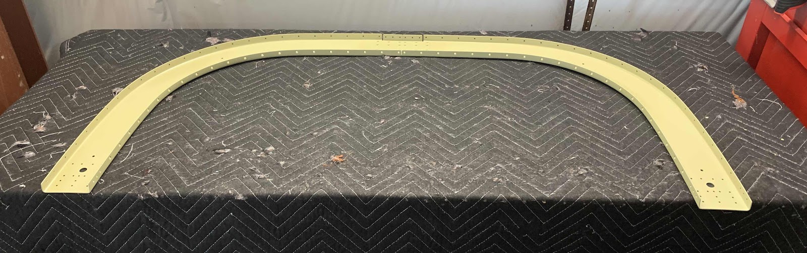
This is the “front 1/2” of the roll bar structure.  Specifically, in the first picture, is the F-01431A-FL (Front Left) and F-01431A-FR (Front Right).  These two pieces are connected together using a F-1231E Roll Bar Splice Plate.  The three pieces were riveted together using 24 AN470AD4-5 rivets.  This is now known as the “FWD Roll Bar Assembly”.

(Note:  The F-10431A-AL (Aft Left), F-01431A-AR (Aft Right) and second F-1231E Roll Bar Splice Plate were assembled in the same manner using 20 AN470AD4-5 rivets…..the remaining four rivet locations will be used later.  This is now know as the “AFT Roll Bar Assembly”.)

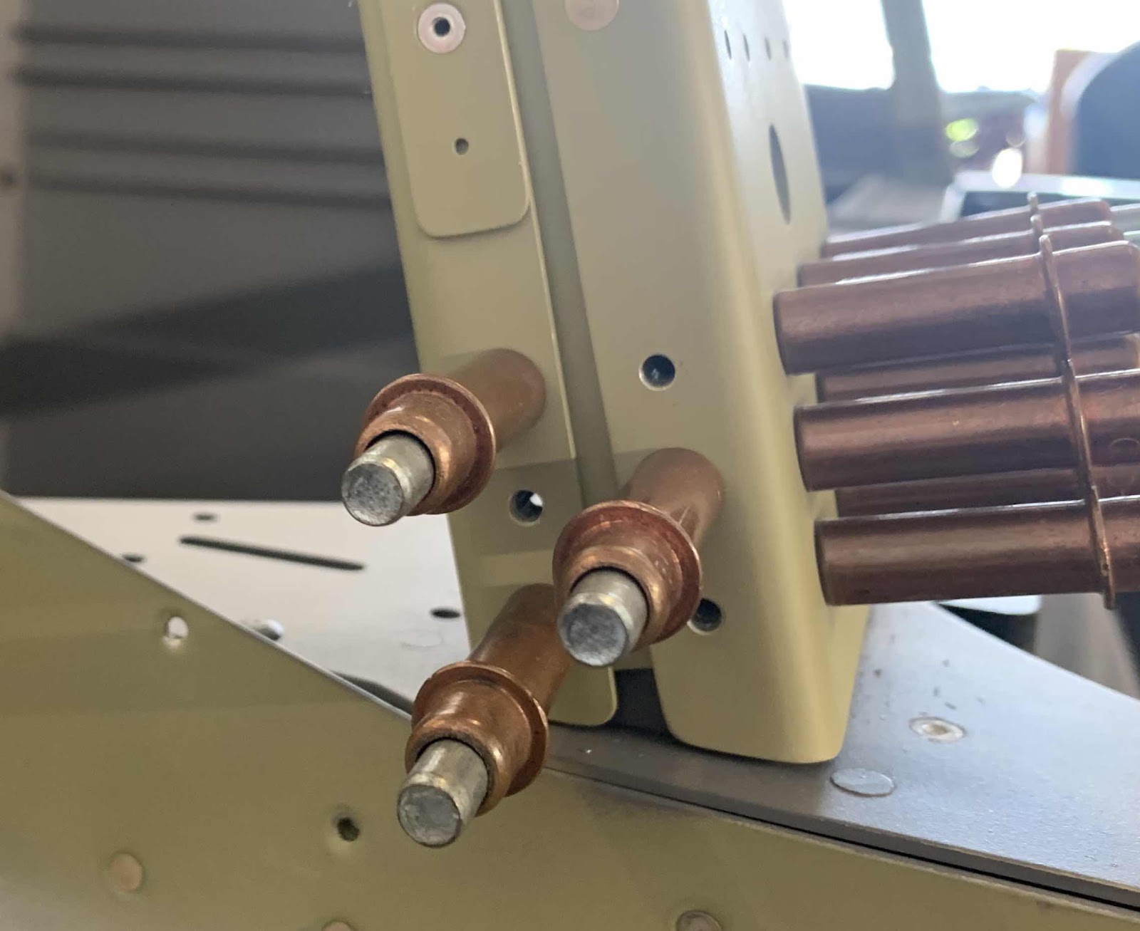
Here is the shop head side of the rivets…..

…..and the manufactured side of the rivets.

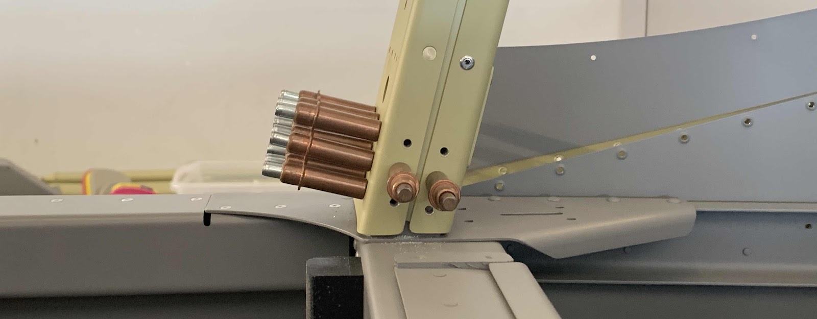
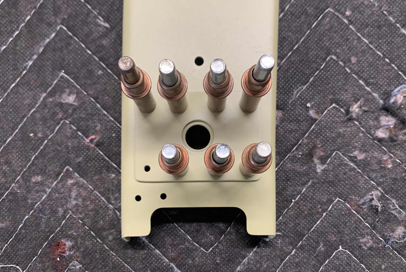
*****Note:  In the three pictures above, you will notice I also countersunk the inboard (lower) holes on the FWD Roll Bar Assembly.  I did this in ERROR!  The plans only call for the outboard (upper) holes to be countersunk (because the canopy and baggage area windows will rest on top of the roll over assembly).  So, instead of 470 rivets in the lower holes, I will have to use 426 rivets.  Not a big deal and the only thing I lost…..the time countersinking the holes.  More on this error in the next post.*****

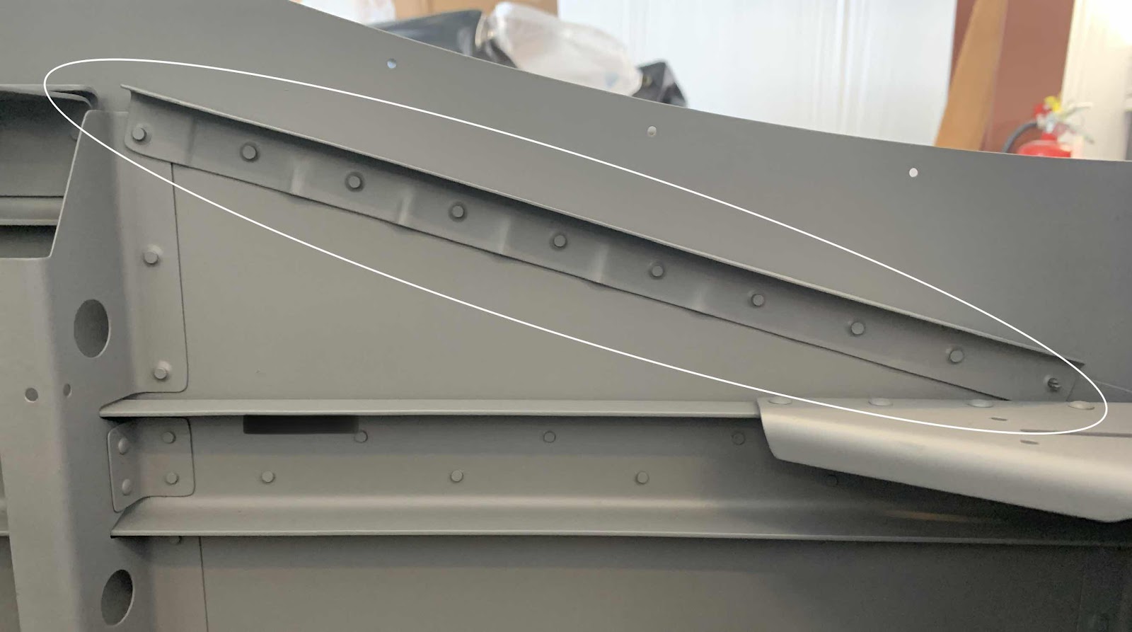
The next step was to cleco the F-01431B Outboard Roll Bar Strap to the FWD Roll Bar Assembly and the F-01431C Inboard Roll Bar Strap the AFT Roll Bar Assembly.  (You will be able to see all these parts with a little more clarity when I rivet them together in the next post).

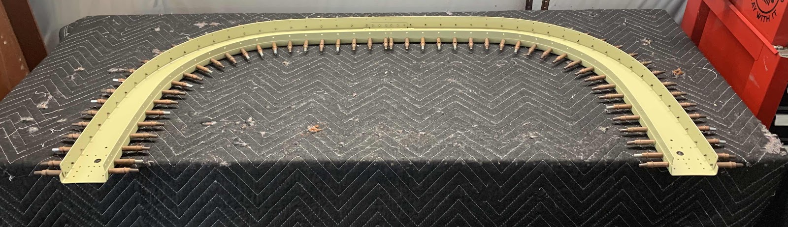
Once clecoed together, all the #40 holes (silver clecos) had to be final-drilled to #30 holes (bronze clecos).  In the picture below, half of the final-drilling is complete…..it’s ALOT of holes!!!!

Additionally, the F-01431D Window Shims were clecoed to the AFT Roll Bar Frame Assembly and Outboard Roll Bar Strap.  In the picture below, you can see the window shims on the bottom side and in the upper center of the assembly.  (They are actually not primed yet).

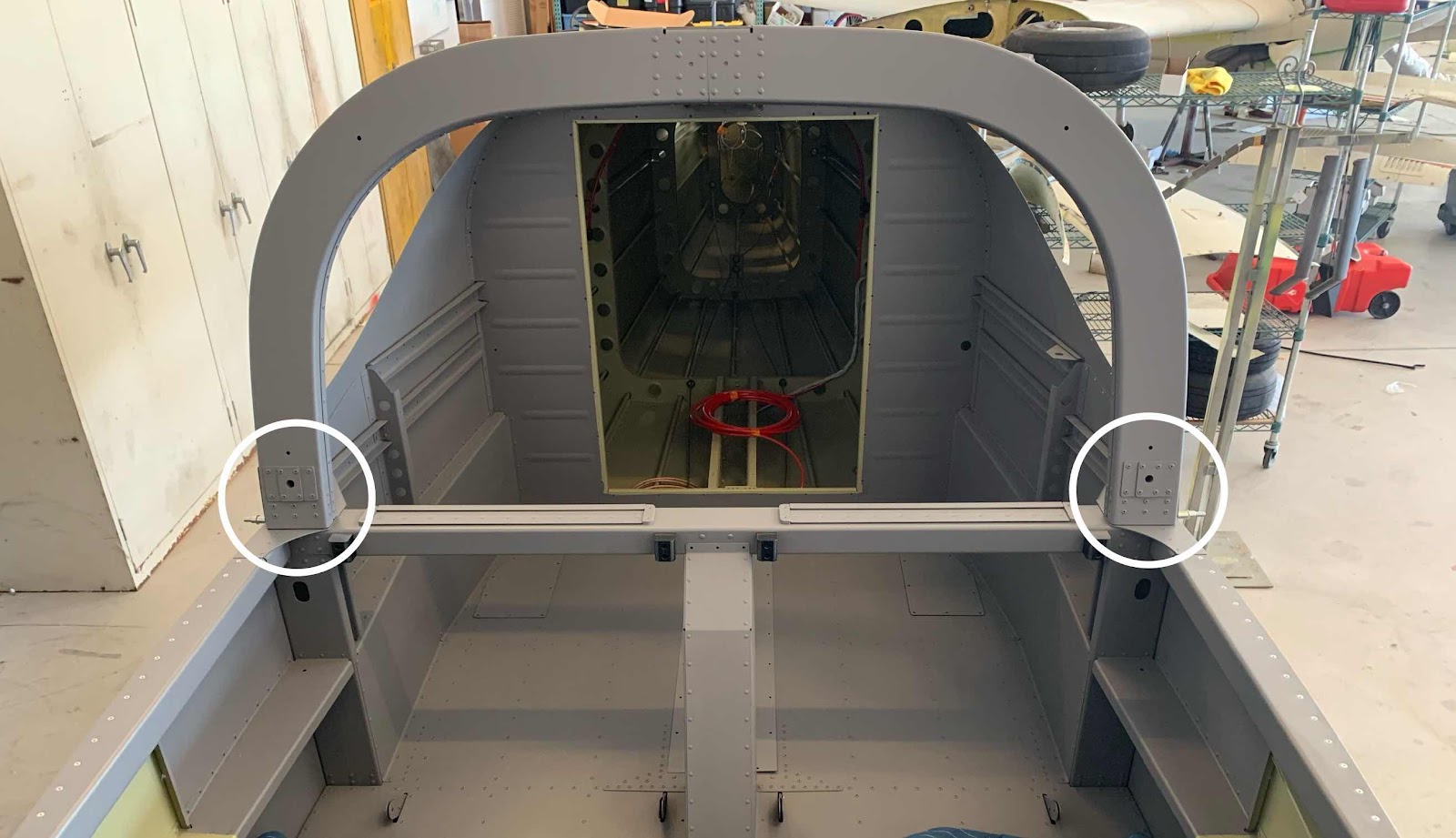
Just another view of everything clecoed together.