Showing posts with label Electrical Power Bracket. Show all posts

Saturday, February 24, 2024

Panel Installation (Part 14) - JVL Aviation’s Electrical Power Bracket

The pictures and work from this post are from January 6, 2024.

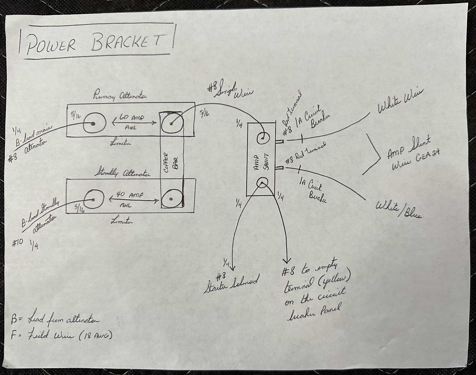
I completed the remaining electrical items (as it relates to the power bracket) in the pictures below (referencing my schematic drawing from the previous post):

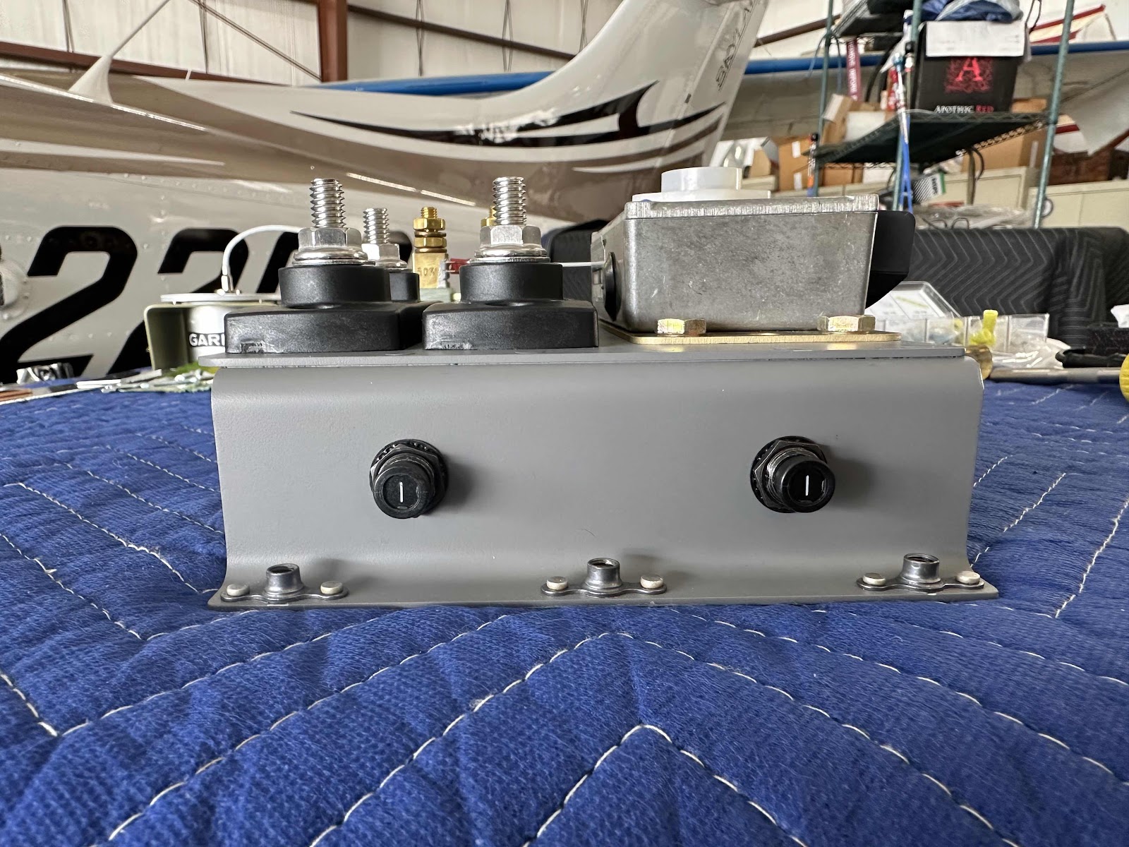
-Fabricated/Installed the bridge wire from the top right post of the upper ANL limiter to the top post of the shunt
-Fabricated/Installed the copper bar between the right upper and lower posts of the ANL limiters
-Installed post #3, #5 and #6 on the standby alternator regulator

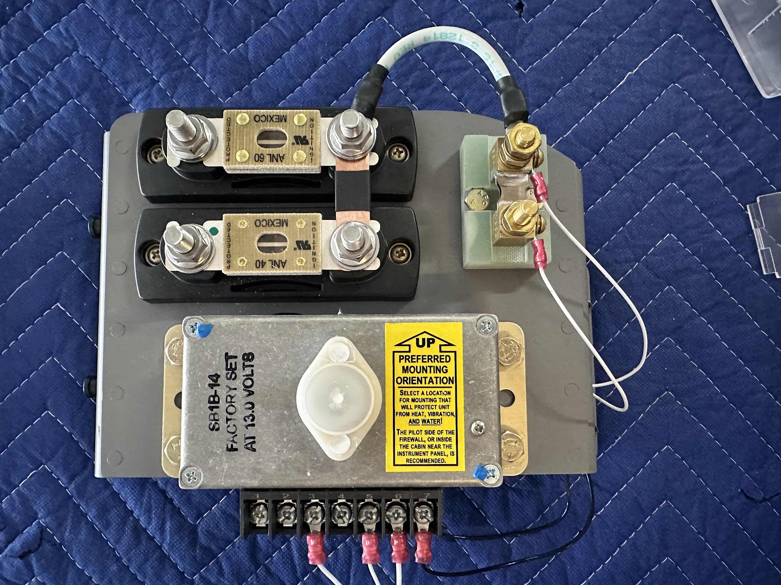
-Installed the amp shunt wire(s) from the GEA 24 through the grommet to the 1A circuit breakers
-Installed the proper sized adel clamp on the back of the bracket to hold the wires

- Installed the starter solenoid wire to the lower post on the shunt
- Installed the circuit breaker panel wire to the lower post on the shunt
- Installed the B-Lead from the main alternator to the left post on the upper ANL limiter
- Installed the B-Lead from the standby alternator to the left post on the lower ANL limiter
- Installed the 60 ANL fuse between the left and right posts on the upper ANL limiter
- Installed the 40 ANL fuse between the left and right posts on the lower ANL limiter

That pretty much covers the JVL Aviation’s Electrical Power Bracket.  There are a couple items I will address to call the installation truly complete.  
1.  I’m gong to turn the 40 ANL fuse the other way, so the opened end of the fuse is facing down (and won’t fall out if the nut gets loose????)
2.  Make sure I have adequate clearance between the wires on the far right and the skin of the airplane.  It doesn’t look it here, but there is about an inch of space between them in the picture 
3.  Install a boot for the wires on the lower post of the shunt (there is plastic covers that will be installed on the limiters)

Friday, February 23, 2024

Panel Installation (Part 13) - JVL Aviation’s Electrical Power Bracket

The work and pictures from this post are from January 3, 2024.

In the previous post, I mentioned the need for circuit protection for the wires coming from the shunt (as required by the electrical schematics from Aerotronics).  To comply with that requirement, I decided to use these 1A Circuit Breakers from Aircraft Spruce.  The two holes on the left side of the zees were actually the PERFECT size to accept the circuit breaker…..so, that’s where they went.

This view shows a couple of things:
- the two white wires attached to the shunt…..
- the two black ground wires attached to the standby alternator regulator (Post #7 and the case)


This is the opposite side of the bracket showing:
-the two white wires from the shunt attached to the 1A circuit breakers (through the rubber grommet)
-two black ground wires from the regulator attached to the ground post (I installed)

For the regulator ground(s) in the picture above, I ended up drilling a separate hole in the zee bracket to accomplish the grounding.  By doing this, the bracket could be removed by only removing the five mounting bolts…..and the ground(s) and associated wiring on the bracket would not interfere or have to be disconnected.  I thought it was the easiest way to do it instead of attaching it to one of the main bracket mounting bolts. 

On the flanges of the zees that will make contact with the sub panel, you can see I sanded a couple of spots.  I ultimately decided to sand the entire length of the flange(s) for grounding purposes.  Additionally, I sanded the backside of the sub panel (forward side actually) that the bracket will contact when it was mounted.  I used this Fine Sander Detail Kit from Aircraft Tool Supply Company to clean the mounting location on the sub panel.

Panel Installation (Part 12) - JVL Aviation’s Electrical Power Bracket

The work and picture from this post is from January 7, 2024.

Back in Part 7, I discussed the decisions I made to get my electrical system “designed” and how/where I was going to mount all the parts and pieces.  Those decisions lead to the fabrication of the “JVL Aviation’s Electrical Power Bracket”, the location on the airplane the bracket was going to be mounted and what was going to be mounted on it.  Now, with all of those decisions and work completed, I needed to figure out how the actual electricity was going to flow between all the parts.  So, after LOTS of guidance and recommendations from Andre at Aerotronics, I drew this very simple schematic of how it was going to work on my plane:

Most of the drawing is pretty self explanatory (to me anyway), but I will explain some of my chicken scratch.  For example, on the top left (primary alternator):

B-lead main (alternator)
1/4:  size of the terminal on the alternator
#8:  gauge of the wire between the main alternator and the left post on the top ANL limiter
5/16:  size of the terminal on the left post on the top ANL limiter

On the bottom left (standby alternator):

B-lead standby (alternator)
1/4:  size of the terminal on the alternator
#10:  gauge of the wire between the standby alternator and the left post on the bottom ANL limiter
5/16:  size of the terminal on the left post on the bottom ANL limiter

The remainder of the drawing lays out the sizes of the terminals and gauges of the wires in the same fashion.  The professional wiring schematics I got from Aerotronics with my panel, also shows a 1A circuit breaker for each of the posts on the shunt (also shown in my drawing).  In a later post, I will show my solution for accomplishing that requirement.

I mentioned at the top of this post about the guidance and suggestions I got from Andre at Aerotronics.  I’ve said it before and I’ll say it again…..Jason and Andre have been a wealth of information and knowledge…..I can’t recommend their services enough.  I literally spent hours on the phone with Andre (over many separate phone calls) asking his advice and getting direction on best and safe practices.  They are some great dudes!

*****DISCLAIMER*****

The electrical schematic and system shown on this post, and in my entire blog, are my own design and applies only to my airplane.  If this information helps you, great.  But, please do your own research and seek guidance from professionals when designing the electrical system for your own airplane.  

Panel Installation (Part 11) - JVL Aviation’s Electrical Power Bracket

The work and pictures from this post are from September 3, 2023.

Now that the bracket has been completely trimmed and formed to fit the plane, I repainted it and attached the six K1000-3 nutplates using AN426AD3-3.5 rivets (the same hardware used on the fuel tanks in Section 18).  Here is the front side…..

…..and underneath.

The 1/8” of material I trimmed off the zee flanges leaves enough space for the nutplates to sit on and the appropriate edge distance for the rivets.


Now, I installed all four of the parts onto the completed bracket with the hardware described in Part 8.  Here are a couple of angles:


I got a little happy with the torque seal and put it on the nuts underneath after everything was mounted.  It’s kinda like Frank’s Hot Sauce, “I put that S**** on everything”!

Finally, here is the initial “mounting” onto the airplane using AN3-4A bolts.  I didn’t show it, but prior to installing the nutplates on the zee brackets, I match-drilled the five mounting holes into the sub panel.  I marked the five holes and used a 90° air drill to make the holes (from forward to aft…..there was not enough room with the avionics to go the other way…..mostly).  It also made more sense to match-drill the holes from the side the bracket would be mounted on.

This is looking at the opposite side of the sub panel (looking forward).  From this angle you can see the five AN3 bolts I used to mount the bracket to the sub panel.  

Panel Installation (Part 10) - JVL Aviation’s Electrical Power Bracket

The work and pictures from this post are from September 2, 2023.

After trimming the bracket, I wanted to form the upper right edge and make it look better.  The upper hole in the flange of the zee looked really weird after I trimmed the material away.  Especially, that narrow little strip of material between the edge I cut and the side of the hole.  In the first picture, I marked with a sharpie my initial thought to remove material around the hole.

Then, I thought why?  Why not use the radius of the hole…..to remove the hole?  (The inner sharpie mark).

This picture shows the material removed along the hole’s radius.

To finish up, I removed all the paint previously applied to the bracket (however, the Alodine is still on the bracket).  Then, I sanded all the formed edges and zee flanges until they were complete and how I wanted them.  Here is the completed upper right corner of the bracket…..

…..looking straight down…..

…..from underneath (with the nutplate rivet holes countersunk)…..

…..and the left edge.

Monday, February 19, 2024

Panel Installation (Part 9) - JVL Aviation’s Electrical Power Bracket

The work and pictures from this post are from September 2, 2023.

As I mentioned in the previous post, the bracket had to be MODIFIED again.  Once I finished making the bracket, I did a test fit in the location I wanted to mount it in the plane on the sub panel.  Come to find out, it was just a “smidge” (technical term) too wide.  So, I had to trim off about 1/8” of material from each tank zee.  I used my die grinder with a cutoff wheel to trim the material and then sanded the edges with 220 grit sandpaper and a sanding block.

There is just enough material to rivet the nutplates to the tank zees.  (Pictures of that in the next post).


Because of the bend in the F-01471 Forward Top Skin, a small portion of the upper right hand corner also had to be removed.  Again, I used my grinder and cutoff wheel to trim this area. The two pictures below show the results.

This is after a little bit of sanding to remove the sharp burrs.

Saturday, February 17, 2024

Panel Installation (Part 8) - JVL Aviation’s Electrical Power Bracket

The work and pictures in this post are from August 25, 2023.

After deciding on the appropriate layout of the four parts, I started to actually fabricate the physical bracket.  It took me several iterations to get exactly what I wanted…..which is why the bracket in the four pictures below seems somewhat “complete”.   However, THIS version will also have to be MODIFIED….as you’ll see in a couple of future posts.

I initially used my 9” band saw to cut the “face plate” out of the .063 aluminum sheet and used 220 grit sand paper to smooth the edges and round the four corners.   Next, I clamped each of the four parts to their respective spot on the face plate and match-drilled the appropriate sized mounting holes (the 10 holes in face plate).

Decision #3:  How am I going to “raise” the face plate off the sub panel?  To do this, I used the T-1012 Tank Attach Zee’s from Van’s.  Those dude’s worked perfectly!  They provided the appropriate stand off distance from the sub panel, contained holes in the flanges that were used to match-drill the face plate and acted as a “doubler” due to their thickness.  After the 12 holes were match-drilled (six from each zee), I countersunk those holes to accept AN426AD-3 rivets.

Then, I riveted the two tank attach zees to the face plate.  Here you can see all 12 of the rivets installed and the 10 mounting holes for the four parts.

This view just shows the back side of the bracket with the shop side of the rivets.

After the three bracket pieces were riveted together, I installed the four parts on the face plate.  I used AN3 bolts on the shunt (which fit perfectly in the notches on the base), AN4 bolts on the standby alternator regulator and AN525 screws on the current limiter bases (which also fit perfectly in the recessed mounting holes)…..and the appropriate sized washers and AN365 nuts on the back.

Wednesday, February 14, 2024

Panel Installation (Part 7) - JVL Aviation’s Electrical Power Bracket

After getting the physical panel installed on the frame, I started thinking about how to get electrical power from the battery to the panel…..and through everything else that requires power.  I looked at MANY builder sites and posts on VAF to get ideas of how other builders were accomplishing this.  I found a few ideas from both sources, but ultimately decided to use what I learned to develop my own “bracket”.  I started the whole process with these four parts:

- G3X Shunt
- ANL Current Limiter Base (x2)
- B&C Standby Alternator Regulator (SB1B-14)

Decision #1:  Where would these four parts be mounted on the airplane?  I found that some builders mounted each of the four parts directly to the firewall (on the pilot side), but I didn’t want to drill/add any “extra” holes in the firewall.  I even saw a few installations on the engine side of the firewall.  Another consideration for the mounting location was the distance apart the four parts would be….length of wire runs, obstructions to the wire runs, gauge of the wire, wire management, etc.  Taking all of that into consideration, I decided to mount all four of the parts together in one location…..on the custom bracket I was going to fabricate.

JVL Aviation’s Electrical Power Bracket

Decision #2:  Where on the airplane would this electrical power bracket go?  I decided it would go on the left side (pilot side) of the sub panel between the sub panel and the firewall.  You will be able to see this visually in later posts during the actual installation.

Now, to start designing the bracket.  First, I took a bunch of measurements in the location I decided to mount the bracket.  Then, I ordered two pieces of sheet aluminum from Van’s to fabricate it.  One sheet was AS3-040x8x18 and the other was AS3-063x12x18.  After playing around with each of the two “sizes”, I decided on the thicker .063 sheet…..solely because it was stronger.  This picture shows the four parts arranged on the aluminum sheet…..with some additional aluminum sheets used to gauge the bracket plate size.

After consultation with some maintenance brains I trust, I decided this would be the final layout for the four parts.