This blog was created to memorialize the building process of my Van's Aircraft RV-14 and to satisfy the requirements for certification in the Experimental Amateur Built Aircraft category. It will also serve as a central location for ME to reference in the future on processes and techniques I used during the build. Additionally, it will allow my family, friends, and other interested builders the opportunity to follow along during my build…..and might be helpful to someone along the way.
Showing posts with label Section 23-Aileron Actuation. Show all posts
Friday, October 23, 2020
Wednesday, September 30, 2020
Wings, Aileron Actuation (Part 5)
I previously started work on this section back in March of 2019. Again, since we are waiting on the Finishing Kit, I’m completing small unfinished jobs.....this is another one of them.
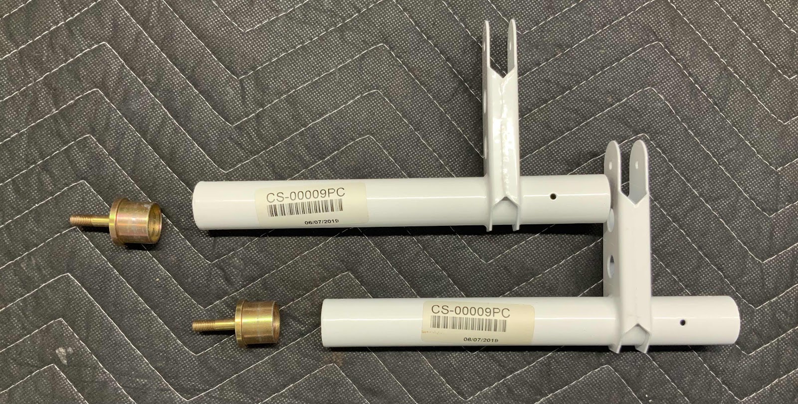
Below are the two CS-00009PC Aileron Torque Tubes and two VA-162 Pushrod Ends. The Pushrod Ends get inserted into the “long” end of each of the Torque Tubes. The two pieces were then match-drilled #30 to the prepunched holes in the Torque Tube. The pieces were then disassembled, deburred and primed. I used a paint brush to paint the inside portion of the Torque Tube that will accept the Pushrod Ends and the “flange” of the Pushrod Ends.
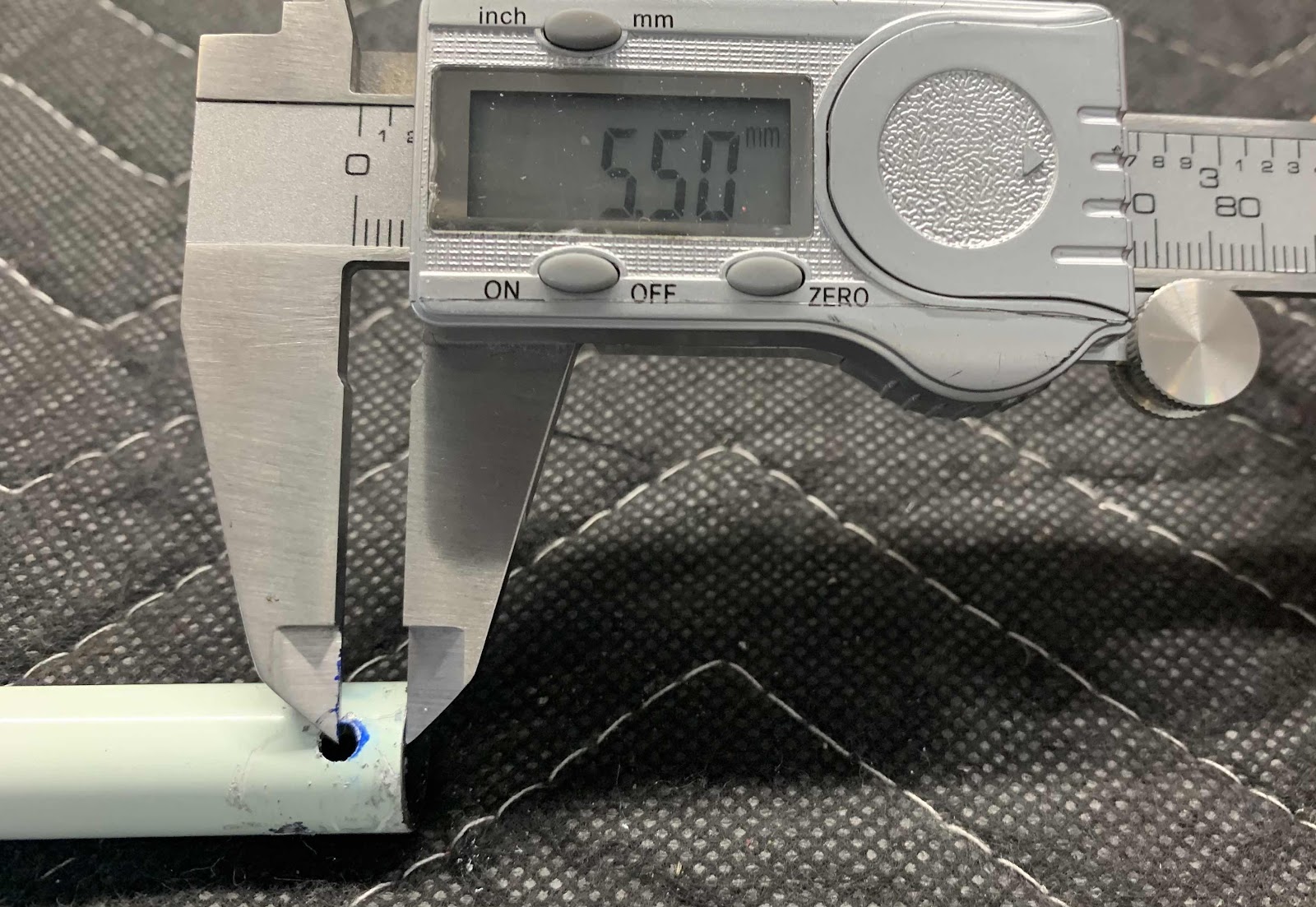
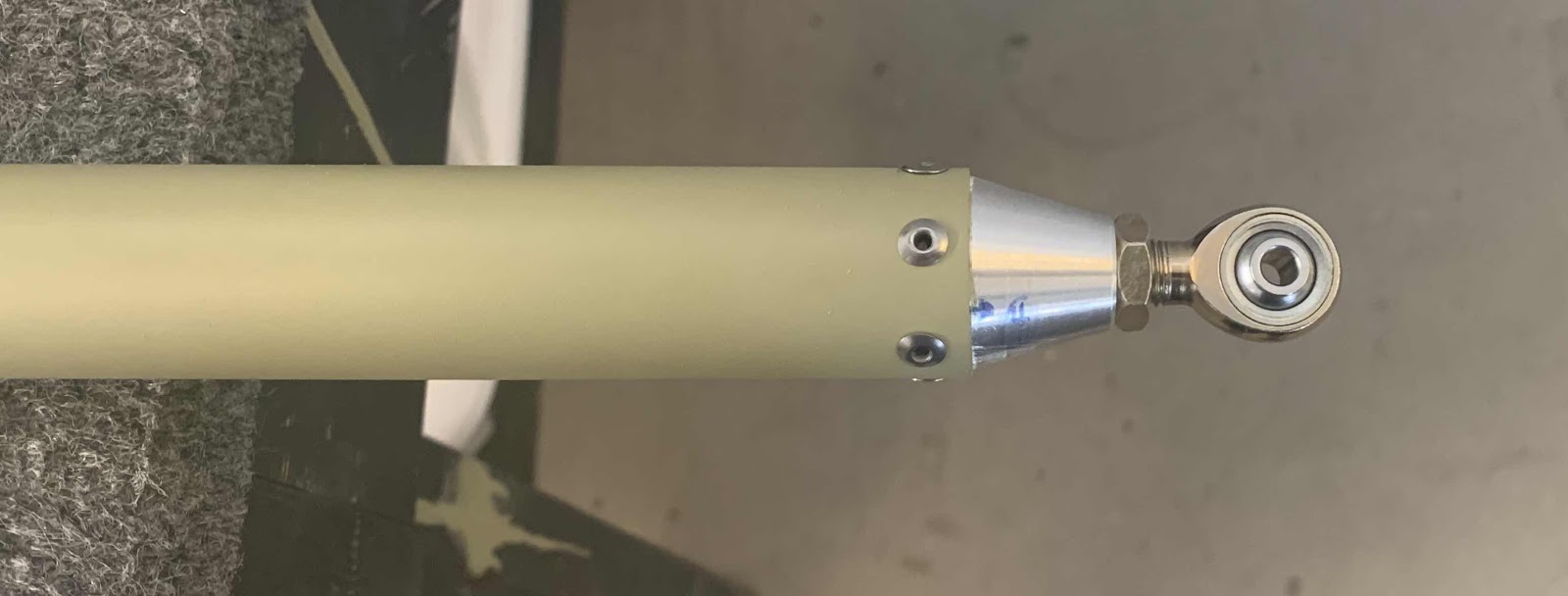
The Pushrod End were then inserted back into the Torque Tube (still wet with primer) and riveted together with four MSP-42 rivets (two on each assembly). This picture shows the rivets installed. This assembly is now called the CS-00009 Torque Tube Subassembly.

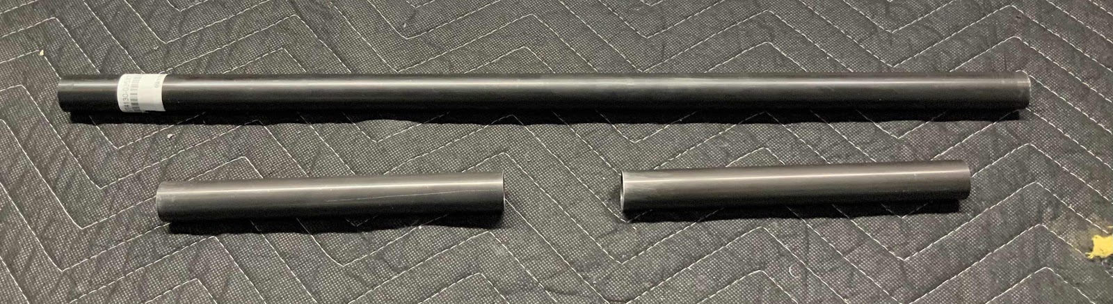
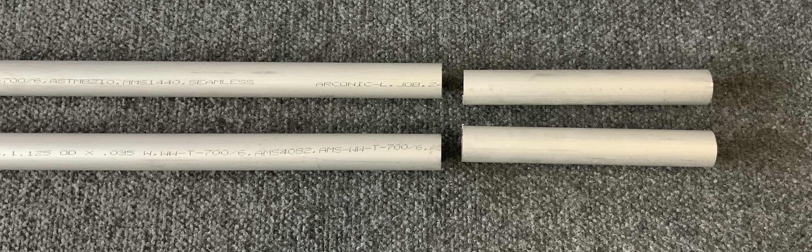
The next step was to fabricate two CS-00009B Torque Tube Collars with stock ST4130-035x7/8x22. Each Collar is cut to 7 5/16 [185.7 mm]. The picture below shows the stock material and the two Collars cut to length. I used a hacksaw for the initial cut and sanded to the exact length with 220 grits sandpaper.
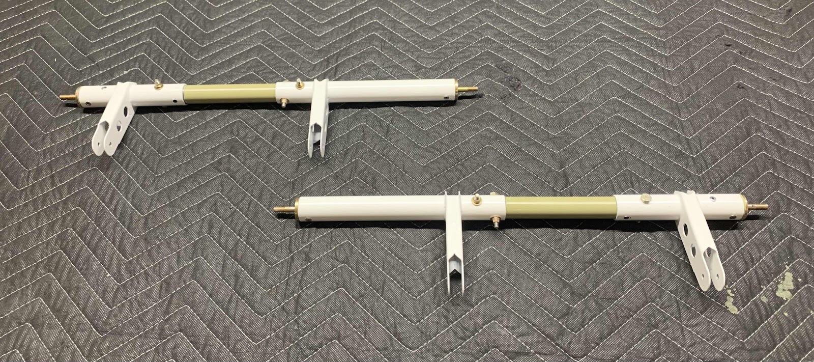
The Collars get inserted 1 1/2” [38.1 mm] into the CS-00009 Torque Tube Subassemblies. So, I measured 1 1/2” from one end of each Collar and marked them with a sharpie. The Collar was then inserted into the Torque Tube Assembly up to the 1 1/2” mark. The Collar was then match-drilled with the four pre-punched holes in the Torque Tube. Now the pieces need to be primed. I used a large syringe to squirt primer “inside” the Torque Tube Subassembly and rotated it around to cover the entire inside with primer. I then used orange tape to mark off the 1 1/2” on the Collar and used a spray gun to paint the remaining portion of the Collar. Lastly, I use a paint brush to coat the 1 1/2” portion of the Collar and inserted the two pieces together. They were secured together using two AN3-13A bolts, NAS1149F0332P washers and MS21042-3 nuts. This picture shows all of that completed. I will eventually torque the four bolts.
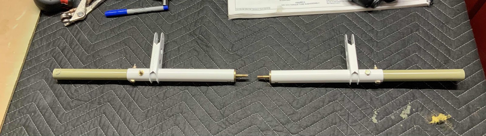
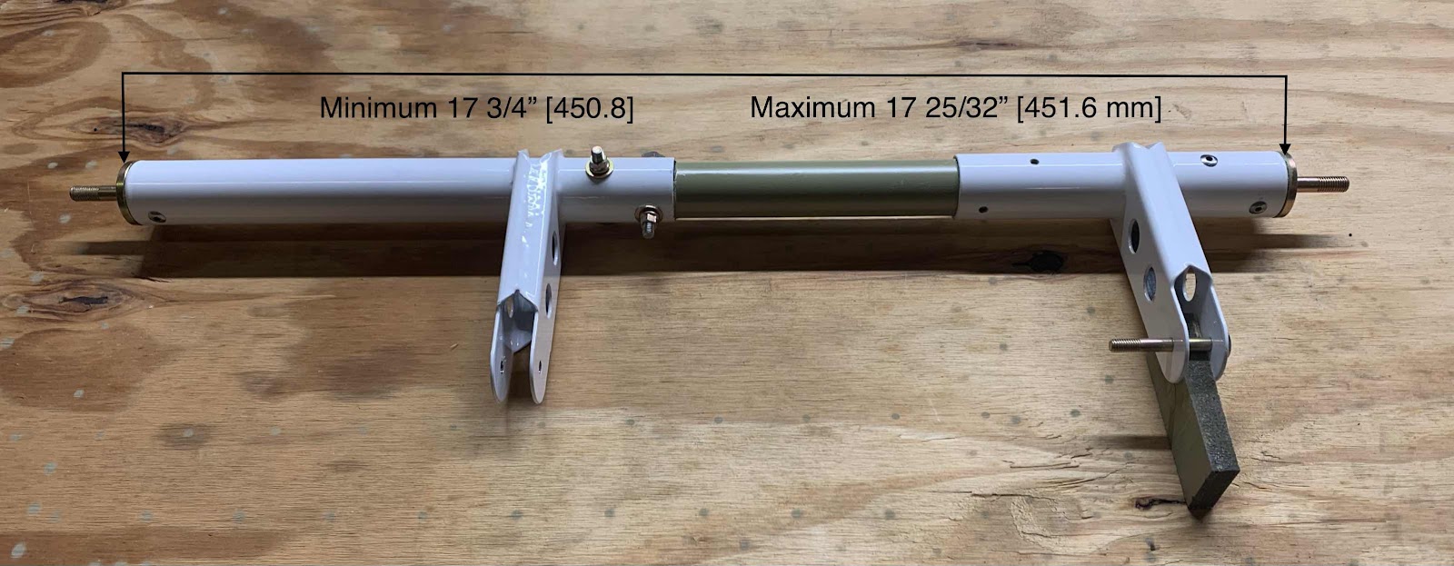
On the right hand side of the picture below is the WD-1014 Torque Tube Subassembly. It was previously completed in the same manner as described above for the CS-00009 Torque Tube Subassembly (specifically, the attachment the VA-162 Pushrod End). Now, with the second Subassembly completed, it also needs to be attached to the Collar. The plans call for the minimum and maximum distances shown below.....(I chose the middle.....451.2 mm). Once the distance is set, the four prepunched holes in the Torque Tube Assembly are match-drilled to the Collar and clecoed.
Lastly, for now anyway, a temporary bolt was installed in one of the match-drilled holes with the WD-1014 Torque Tube Subassembly to hold the assembly together and keep the appropriate parts together. The next step is to install the assembly into the Wing Root area.....which I will do in a later session.

Thursday, July 11, 2019
Wings, Aileron Actuation (Part 4)
Continuing on from yesterday’s work.....
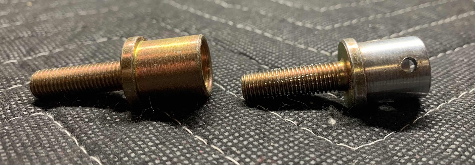
Shown below are the four AN490HT8P Threaded Rod Ends. Those four Rod Ends have to be inserted into the ends of the Bellcrank to Aileron Pushrods fabricated in Part 3. However, the Rod Ends are a little fatter than the opening of the Pushrods.
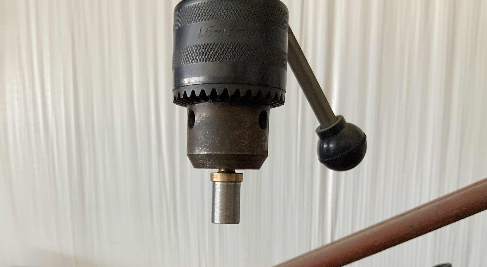
So, to fix this “problem”, I put two 7/16 nuts on the Rod Ends (far right in the picture above) to protect the threads of the Rod Ends. Then inserted the nuts into a drill press as shown below, turned it on and used the vixen file to remove material from the Rod End. Once enough material was removed, I used 220 grit sandpaper to smooth out any rough edges edges created by the file (careful not to make it to smooth and prevent primer from sticking to it in a later step). Worked out very well. (I stole the idea from Shawn).
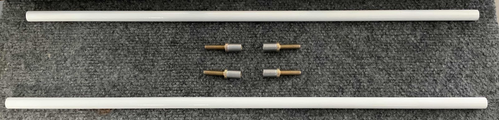
Here are all four of the Threaded Rod Ends after being trimmed as described above (you can see the shiny ends). Also shown are the two Pushrods that the Rod Ends will be inserted into.....
.....and the Rod Ends inserted into the Pushrods. This is temporary as holes will have to be drilled and the parts riveted together.
The next step is to drill the two holes in each end for the install of the AN470AD4-11. These rivets will hold the Pushrods and Rod Ends together.....more on that during the next work session.
Wednesday, July 10, 2019
Wings, Aileron Actuation (Part 3)
So, I’m currently in a position on Section 26 (MID Fuse Lower Structure) and Section 27 (Firewall) that I will need a rivet helper to finish up the sections. So, I audibled back to Section 23 (Aileron Actuation) to finish some unfinished work. Previously, I had to order four AN490-HT8P Threaded Rod Ends from Van’s, because I didn’t notice during inventory, that I had four of the wrong size (bigger). So, I had to pretty much stop work on this section until the parts were delivered. By the time they were delivered, I was already working on another section.....Section 23 had to wait.....until now!
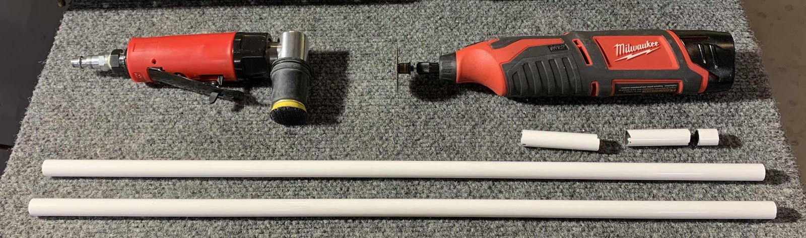
Anywho, today’s session was spend working on the two Bellcrank to Aileron Pushrods. In the picture below, all the white pieces made up one ST4130-035 x 1/2 rod measuring 48 inches. From that rod, two CS-00013 Bellcrank to Pushrods had to be fabricated. Each Pushrod had to be cut to a length of 21 3/8” long. Initially, I cut the rod into two pieces 24” long (using the Milwaukee Rotary Tool with a cutting wheel). From there, I trimmed those two pieces to roughly 21 1/2 inches (again, using the Rotary Tool). Lastly, I used a hand file and the ATS air sander to get the final length correct. Turned out pretty well.
I’ll continue the working on the Pushrods tomorrow.
Saturday, May 11, 2019
Wings, Aileron Actuation (Part 2)
In Part 1, the CS-00012 Torque Tubes and VA-11 Threaded Rob Ends were prepared and ready to be Akzo Primed. I did not treat the Torque Tubes with Alumiprep or Alodine (no particular reason, just didn’t); however, I did scuff the interior and exterior of the Tubes with grey Scotchbrite. To scuff the inside of the Tubes:
1. I grabed the Scotchbrite pad with mechanical fingers and taped a long wooden dowel to the end of the mechanical fingers
2. Inserted the “assembly” into the Tube
3. Rotated the dowel, which in turn, rotated the Scotchbrite pad
4. Repeated this process until I was comfortable with the amount of scuffing inside the Tubes
To Akzo Prime the inside of the Tube:
1. I tapped off one end of the tube
2. Poured a generous amount of Akzo Primer in the opposite end
3. Rotated and “twirled” the primer inside the tube until I was comfortable it was completely coated
4. Poured out the excess primer (if any) and removed the tape
The outside of the Tubes were Akzo Primed simply by holding the middle of the Tubes with my hand and priming the areas I wasn’t holding. After those sections were hung up and dried, I then primed the areas I was previously holding. It worked okay, but I’m sure there is a better way.
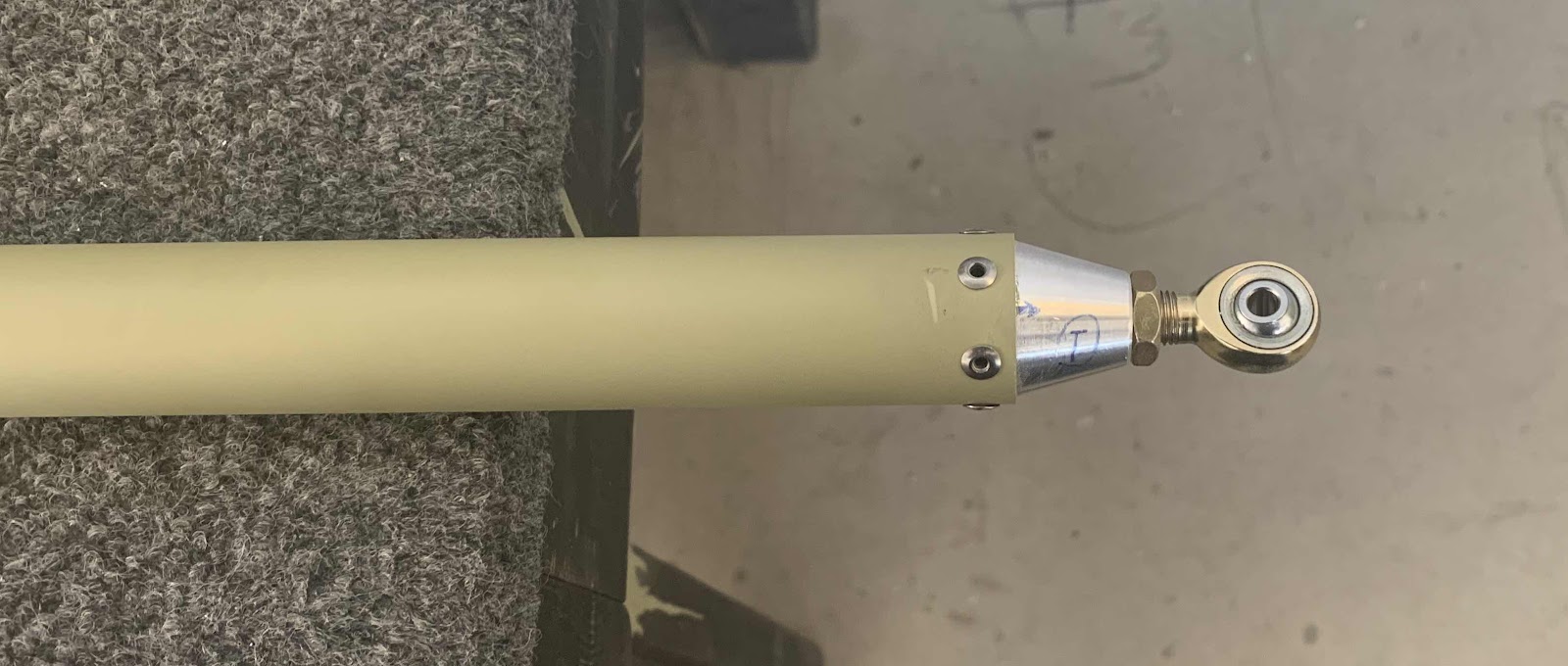
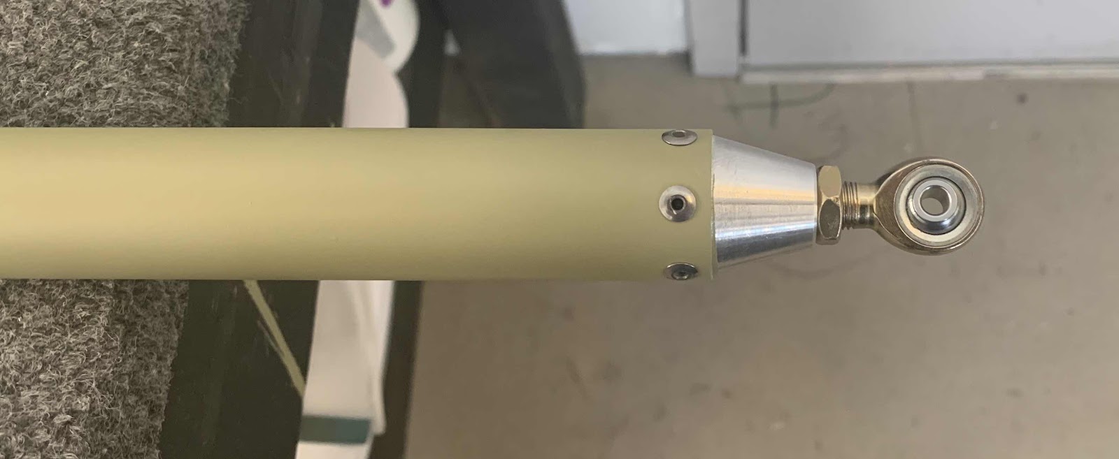
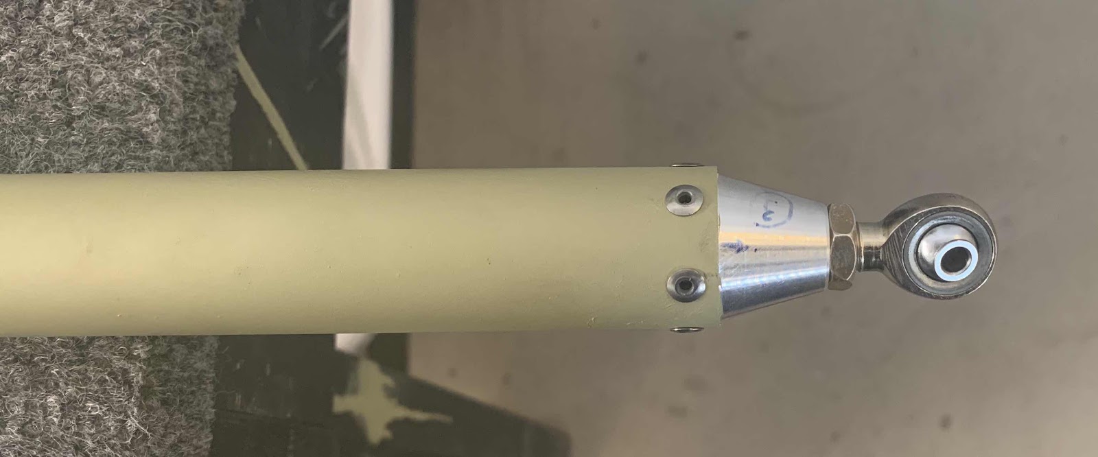
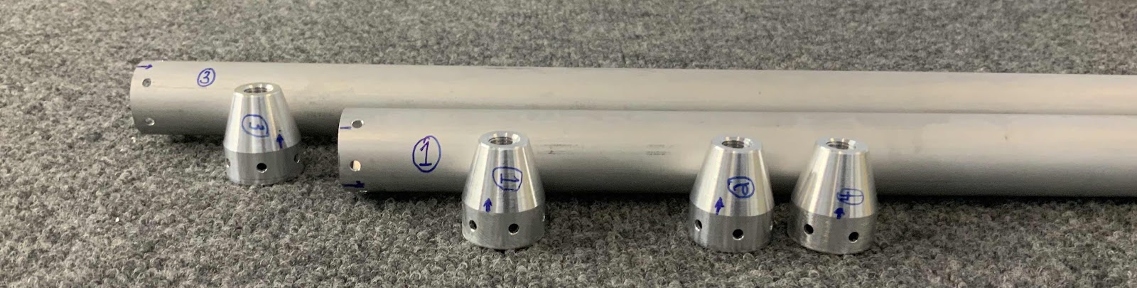
Also in the previous session, each end of the Tubes were marked with a number and the corresponding Threaded Rod End was numbered with the same number. This was done to ensure the pieces went togher the same way as they were match-drilled. After the primer was completely dry, I inserted the Threaded Rod Ends into their corresponding Torque Tubes (with a little sanding with 220) and riveted them into place using MSP-42 blind rivets. Each Tube/Threaded Rod End received six rivets.
Shown below, in order one through four, are the completed assemblies:
The next time I have primer mixed up, I will use my airbrush to prime the exposed ends of the Threaded Rob Ends.
Wednesday, March 27, 2019
Wings, Aileron Actuation (Part 1)
During today’s session, I started work on Section 23, Aileron Actuation. To start, the two CS-00012 Torque Tube to Bellcrank Pushrods had to be fabricated from AT6-035 x 1 1/8 to a length of 64 1/4”. Each Pushrod had to have a little cut off the end as shown below. I was able to use my bandsaw the make these cuts.
Each end of the Pushrods will get Threaded Rod Ends installed, so each end had to have rivet holes drilled in them. The template supplied by Van’s is shown below.....in several pieces. I found that the template didn’t fit completely right. Maybe it was something I did, but I couldn’t get the alignment holes on the template to....well, align with each other.
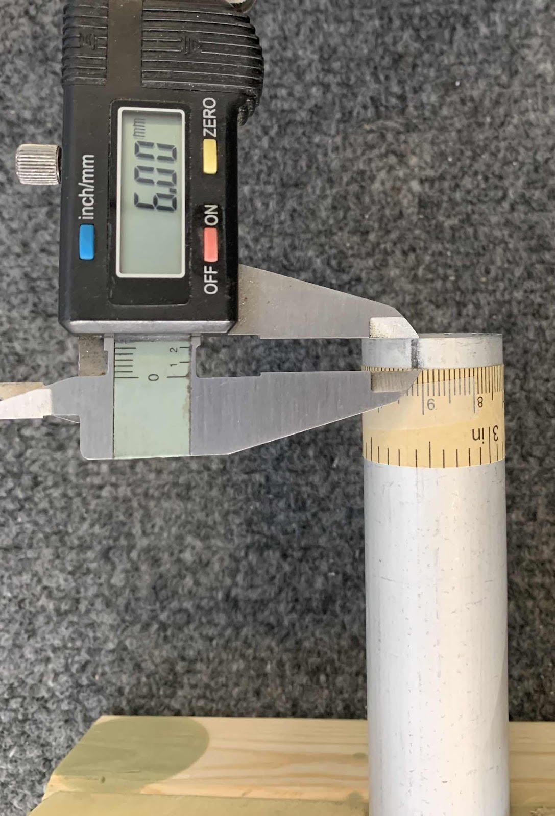
So, I decided to try something different. I got a paper tape measure and wrapped it around the Pushrod. I found the length to be 90mm. According to the template, six rivets will be used on each end to attach the Threaded Rod Ends. So, I divided 90mm by 6 and got each rivet location of 15mm. I then measured the distance of 6mm from the rivet locations to the end of the Pushrods.
Here is my template measred at 6mm from the end of the Pushrod.....

.....and here are three of the rivet locations marked at the 15mm spacing.

.....and here are three of the rivet locations marked at the 15mm spacing.
Next, all six of the marked rivet locations had #40 pilot holes drilled. Here are a couple of the holes after being drilled.

These are the four Threaded Rod Ends that will go in each end of the Pushrods.

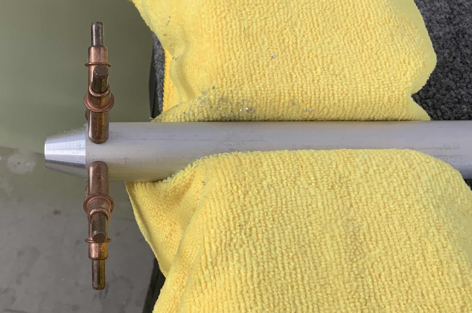
Next, the Threaded Rod End was then inserted into the Pushrod. “Proper alignment of the Threaded Rod End in the Torque Tube to Bellcrank Pushrod is when the end of the Tube coincides with the edge of the taper in the Threaded Rod End”. (If you look at the picture above, you can almost see a “line” where the taper starts). Once the proper alignment was achieved, the Threaded Rod Ends were match-drilled #30 using the #40 pilot holes and a cleco was installed in each hole as it was match-drilled. In the picture below, all six holes are show match-drilled with clecos installed.

Here is another angle. You can kinda see the tapered portion of the Threaded Rod End from this angle.

This process was completed for all four ends of the Pushrods. Prior to disassembly, each end of the Pushrods and the corresponding Threaded Rod Ends were numbers and one hole was marked on each to assure the same parts went back together in the same orientation.

Subscribe to:
Posts (Atom)