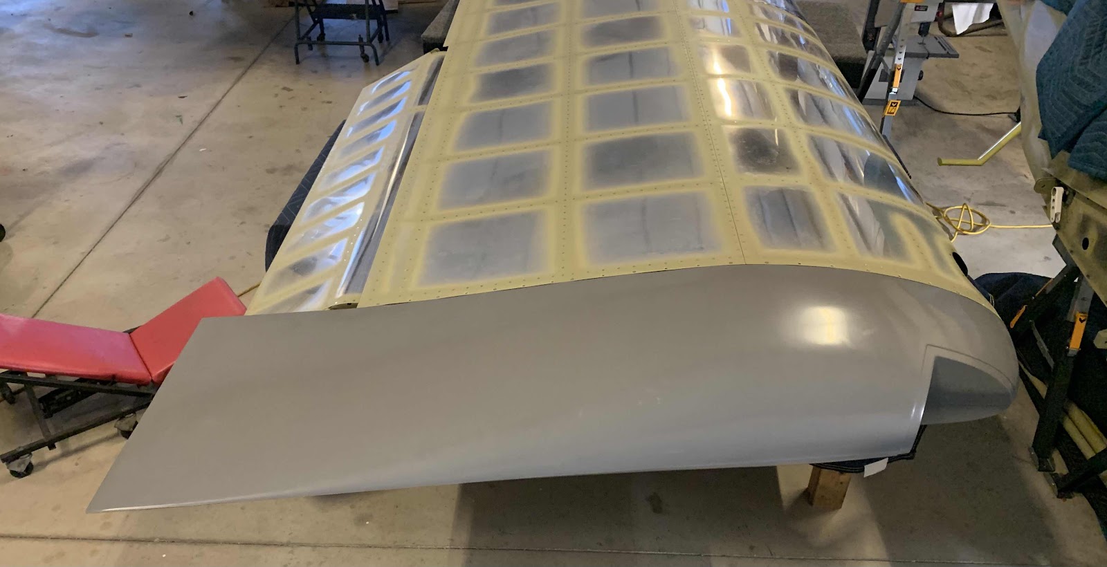
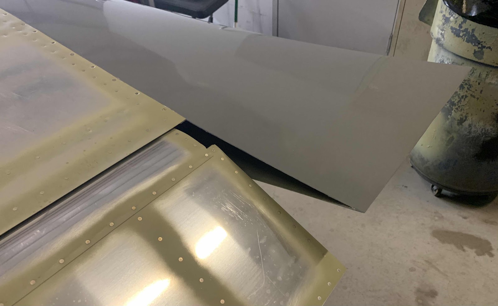
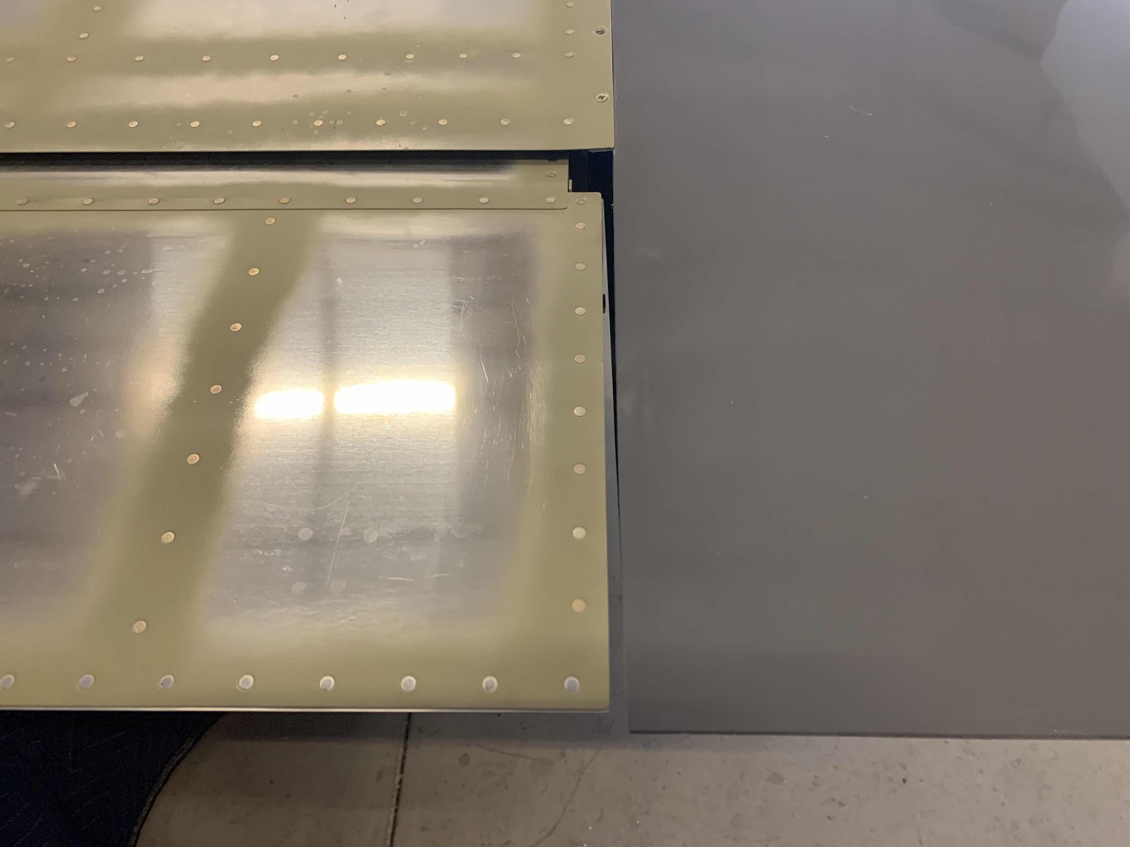
Showing posts with label Section 24-Wing Tip. Show all posts

Thursday, October 15, 2020

Wings, Wing Tip (Part 13)

With the steps completed in Part 12, it’s now time for the final fitting of the Insert into the Wing Tip Fairing.  There are a couple of things I wanted to make sure to accomplish during the final fitting of the Insert:

1. The Insert is equal distance at the forward and aft ends of the nav light “plate” (top and bottom) to the Wing Skin to make sure it’s square to the Wing 
2.  The Insert needed to be at a 90° angle to the Wing Spar (so it’s pointing straight)

So, here is how I accomplished #1.  As the picture below shows, the yellow line is the measurement I wanted to be equal across the top of the nav light mounting “plate”.
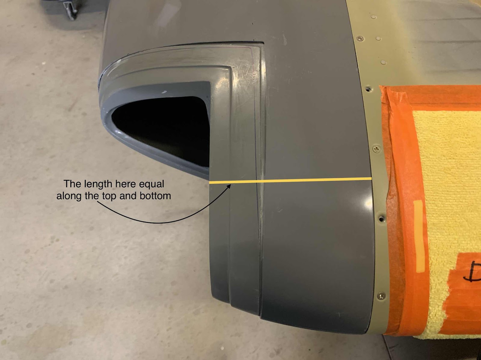
The measurement I settled with was 4” and aligned with the 28 mark on top of the ruler (I guess also 56 on the bottom).  The next few pictures shows the measurement taken near the middle of the Insert and working forward along the Wing.


It was kinda difficult to get any pictures from the bottom side of the Wing, but that measurement came in at 27.....so, pretty damn close.  I’m gonna leave it along before I mess it up.  

Now, to get the Insert 90° degrees to the Wing Spar.  To do this, I used a digital level, set it along the Wing Spar and zeroed it as shown below.
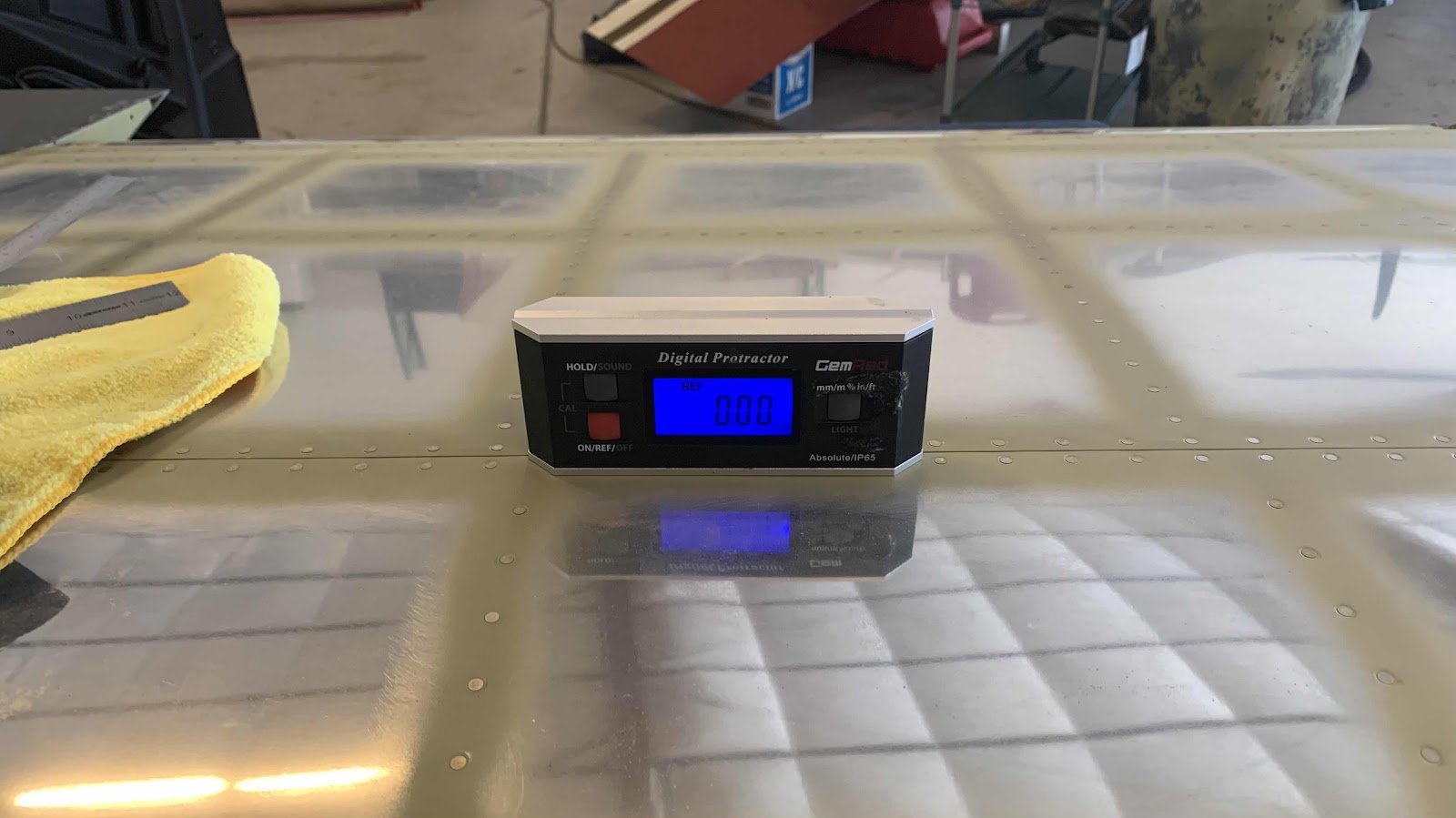
Then, moved the level to the nav light mounting “plate” to get a reading.  After some manipulating (and ensuring to maintain the previous measurements), I achieved the 90° degrees I was looking for.
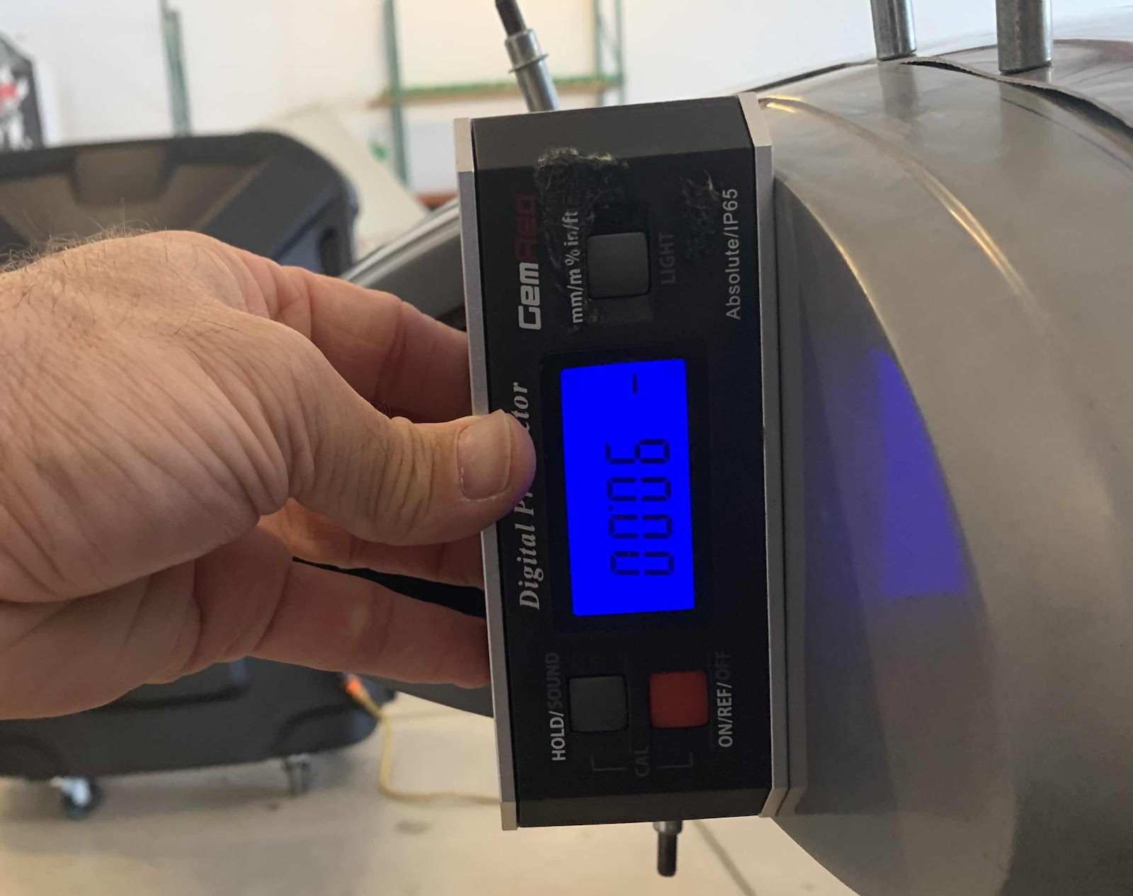
As the correct alignment and measurements were achieved, I drilled pilot holes and inserted clecos to keep everything in place.
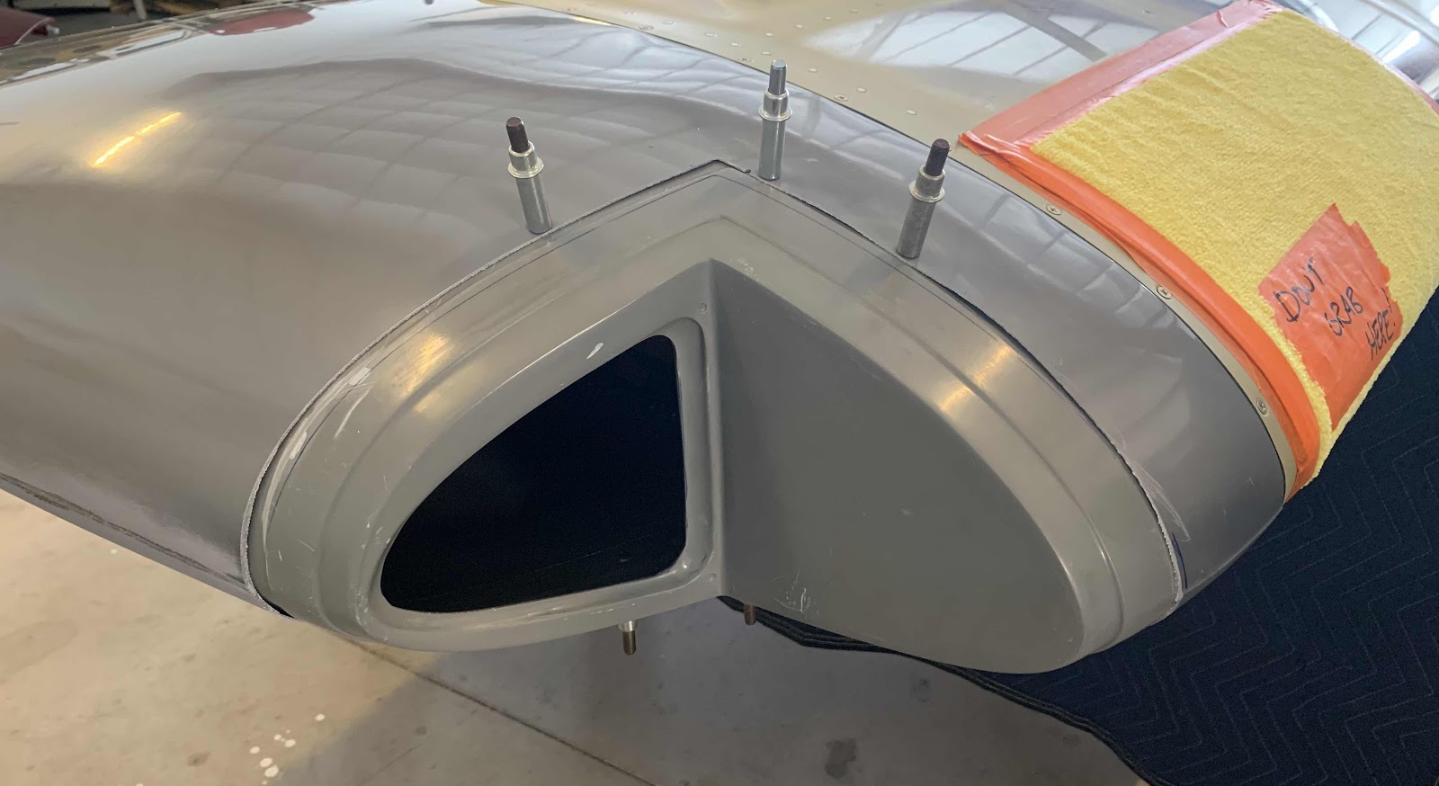
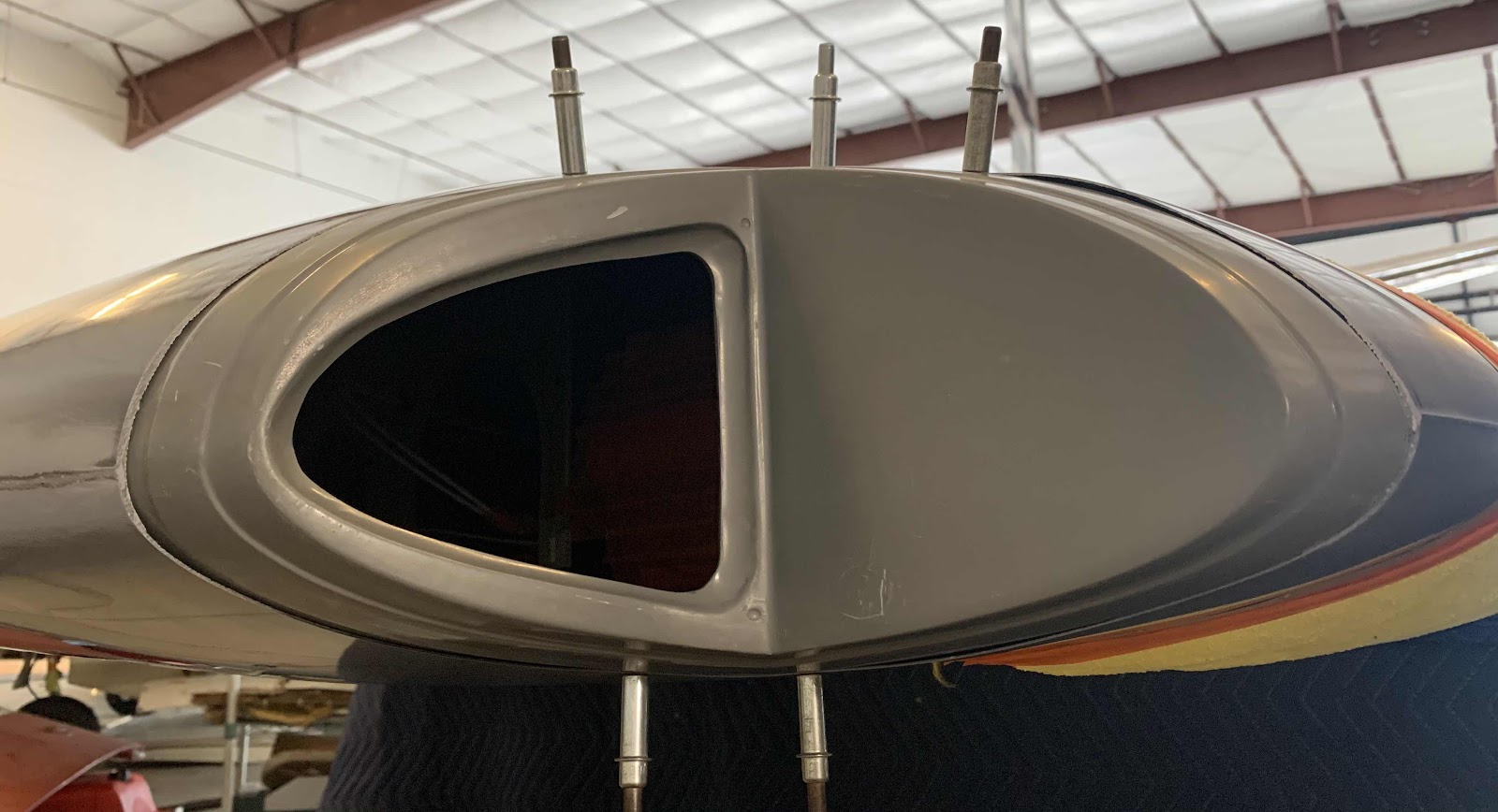
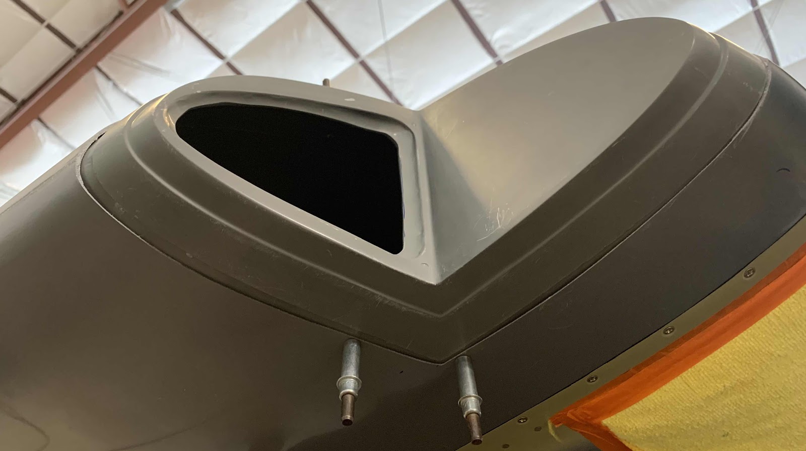


Now, a couple of things still need to be done and I’m debating how I want to do them.  First, the hole I already cut out for the AeroSun VX landing light still needs to be enlarged to accept the actual light itself.  So, I’m thinking I will remove the Insert to complete that step in the instructions (probably easier to handle from both sides of the hole).    Secondly, we need to install the mounting plate for the navigation/strobe light.  I think I will also complete this step with the Insert removed from the Fairing (since I just ensured the Insert mounting “plate” is 90° to the Spar and square to the Wing).

Here is what I’m going to use.....West System 105 epoxy resin and 206 slow hardener (forget about the milled fibers for now).  Now, I will admit, I am brand new to fiberglass work and really have no idea what I’m doing.  So, I need to do some additional research and seek additional guidance prior to doing any of this, so.......

more to follow!

Tuesday, October 13, 2020

Wings, Wing Tip (Part 12)

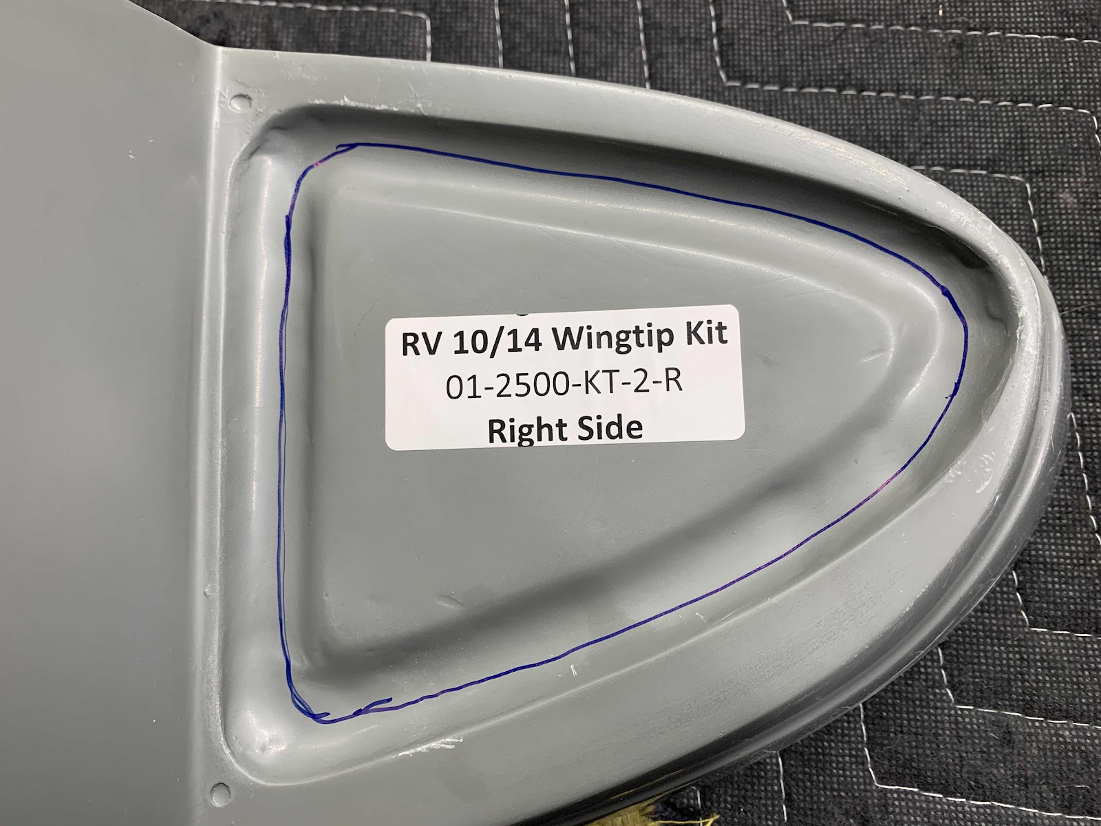
Tonight was a relatively short session, but we made forward progress on the Wing Tip Inserts.  In the previous session, we cut out and removed part of the Wing Tip Fairing to accept the new Insert. Now, there is some material is required to be removed from the Insert itself.  Here is the instructions excerpt from AEROLED:
 The area shown below inside the blue line (where the sticker is located) will need to be removed.  Out line was actually drawn approximately 1/4” below the blend-line.  I figured I could sand the remaining material to achieve the required fit around the AeroSun VX.

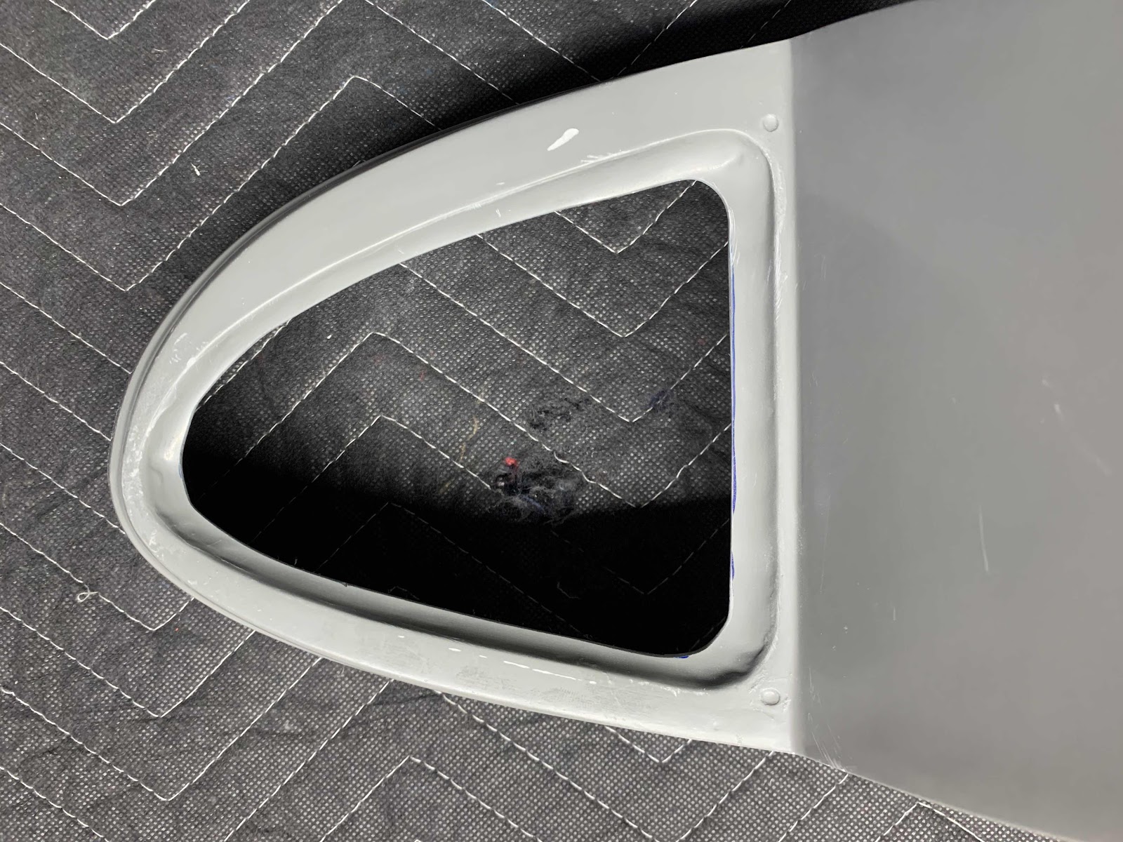
So, used my Milwaukee rotary tool and cut-off wheel to remove the material along the blue line.

Then, we used some 80 grit sandpaper to smooth the rough edges.  Again, the “hole” is slightly smaller than required.....we will enlarge the hole with sandpaper when we get there.

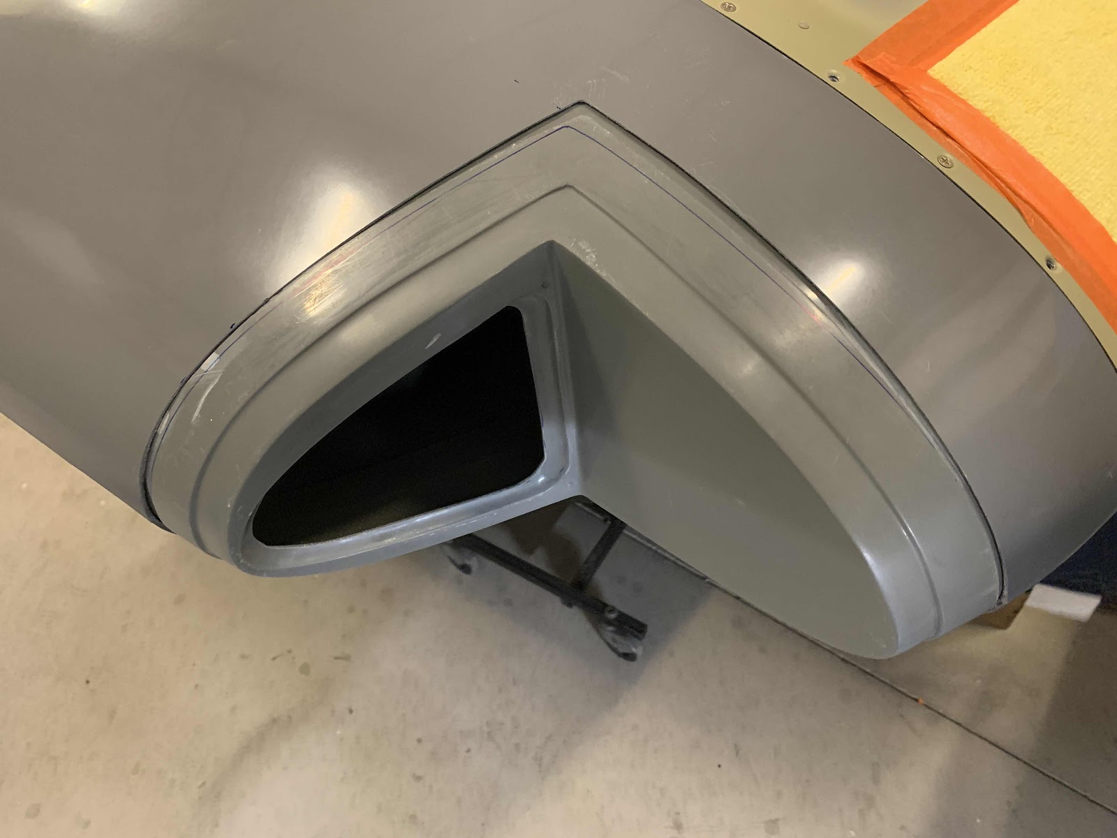
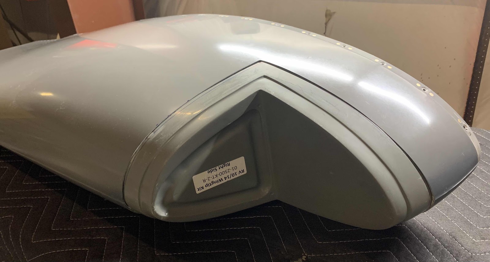
Here is the initial fit of the Insert into the Wing Tip Fairing.  Still some work to do, but making progress.  The Insert will eventually be epoxied into place and filled/blended with micro balloons.

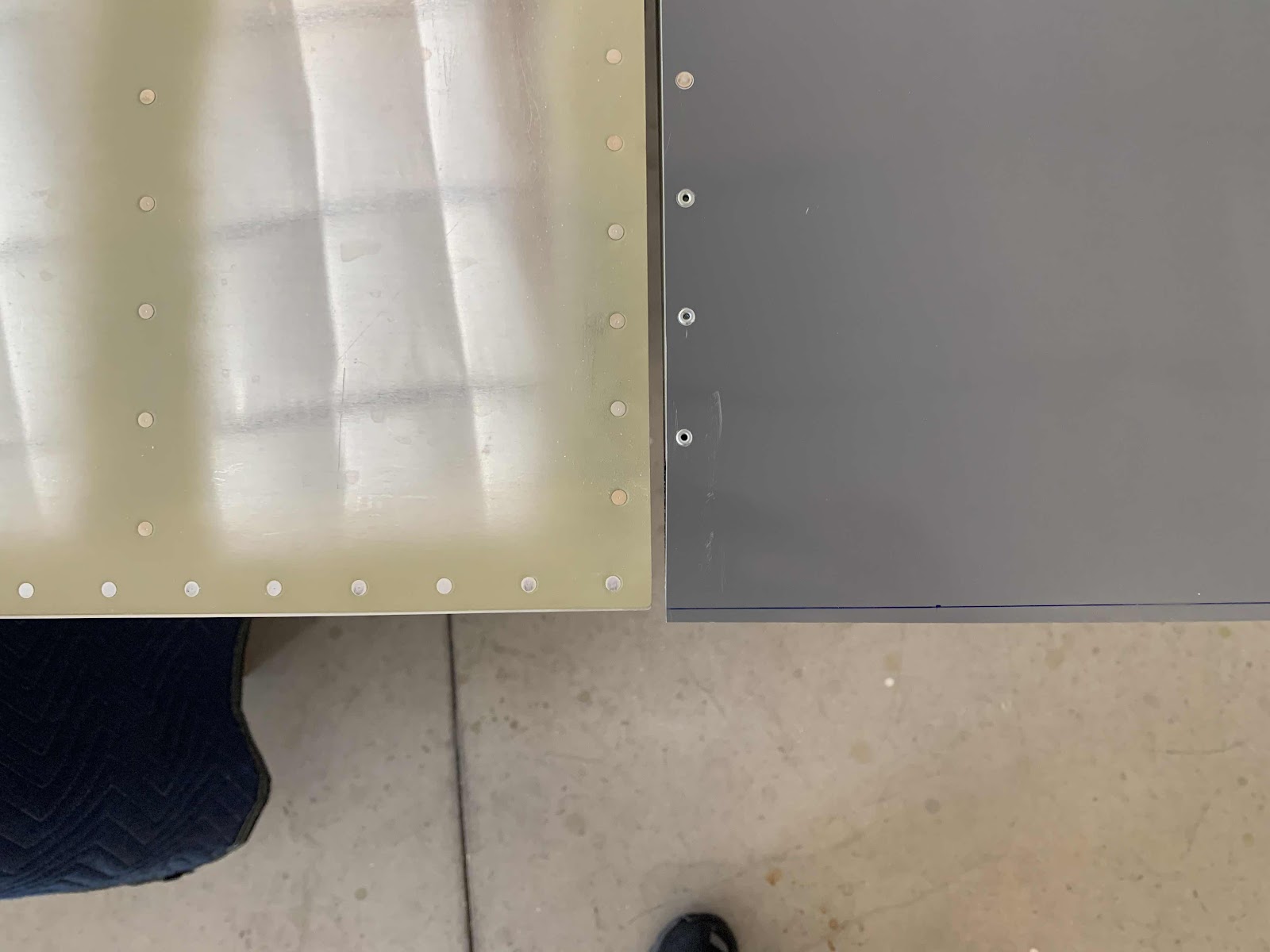
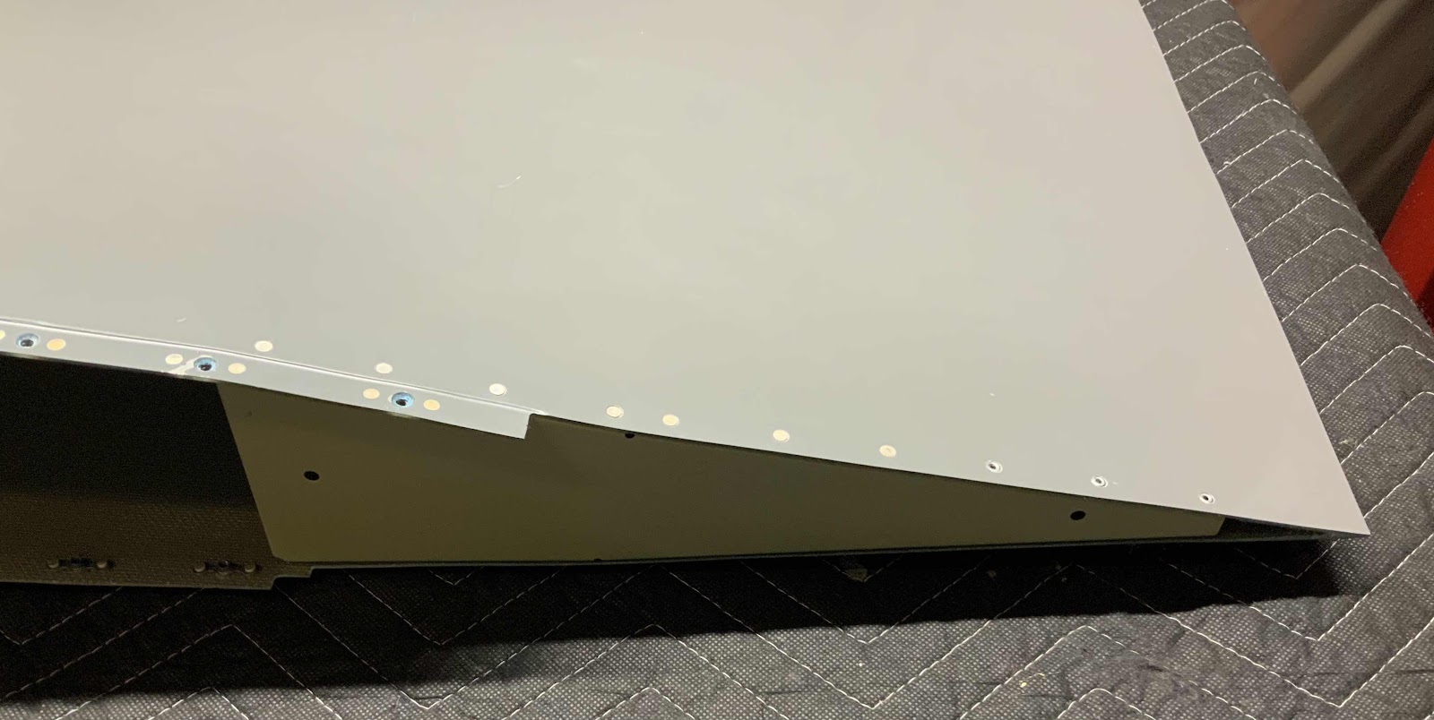
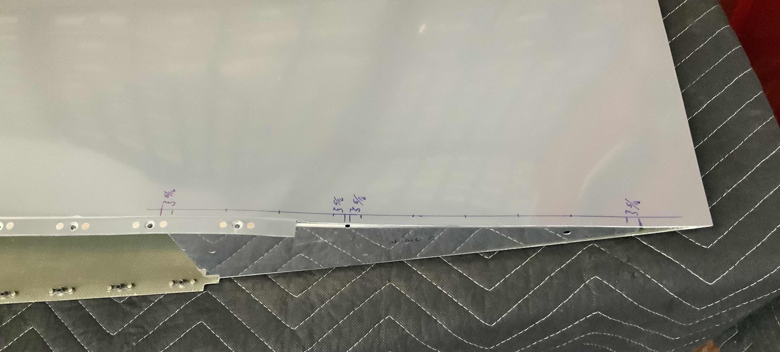
Another area that will need some sanding is the trailing edge of the Wing Tip Fairing.  The plans say to even up the the trailing edge of the Wing Tip Fairing and the trailing edge of the Aileron.  We used a ruler to make the blue line on the Fairing.  Eventually, we will be sanding the Fairing to match the Aileron.  

Here is an overall view of the whole Fairing.  Not a lot of material will need to be removed.  Van’s said if any of the area separates, just fill it and sand to the desired results.

Monday, October 12, 2020

Wings, Wing Tip (Part 11)

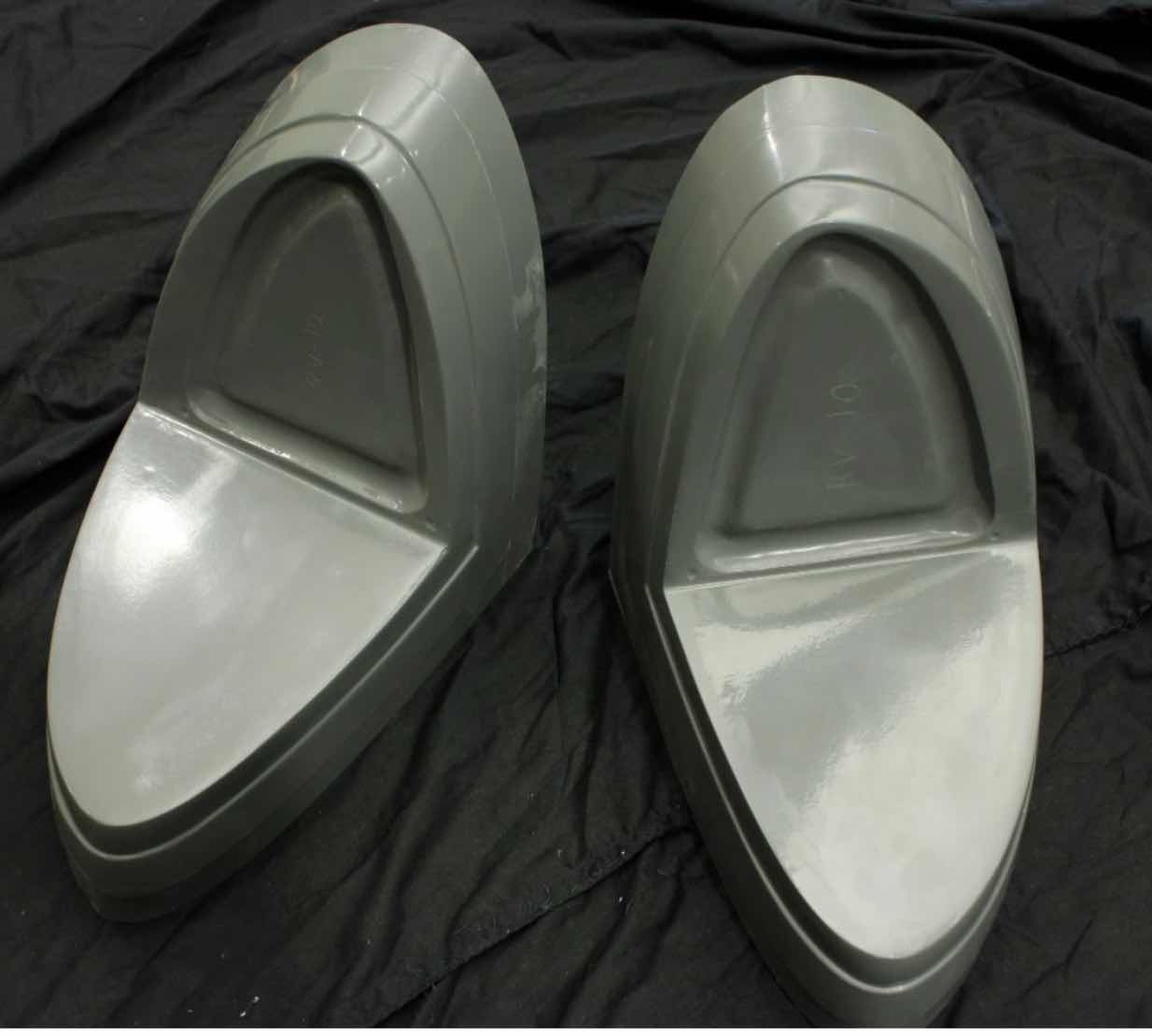
In an earlier posting, I talked about the exterior lighting we decided to use for the RV.  During this session, we started the install of the AEROLED AeroSun VX Landing Lights.  In order to install these lights, both Wing Tip Fairings will have to be modified.  (Here is a link to the instructions from the AEROLED website).  For no particular reason, we will start work on the right Wing Tip Fairing first.  The modification calls for the removal of the forward portion of the stock Fairing and replace it with these.....

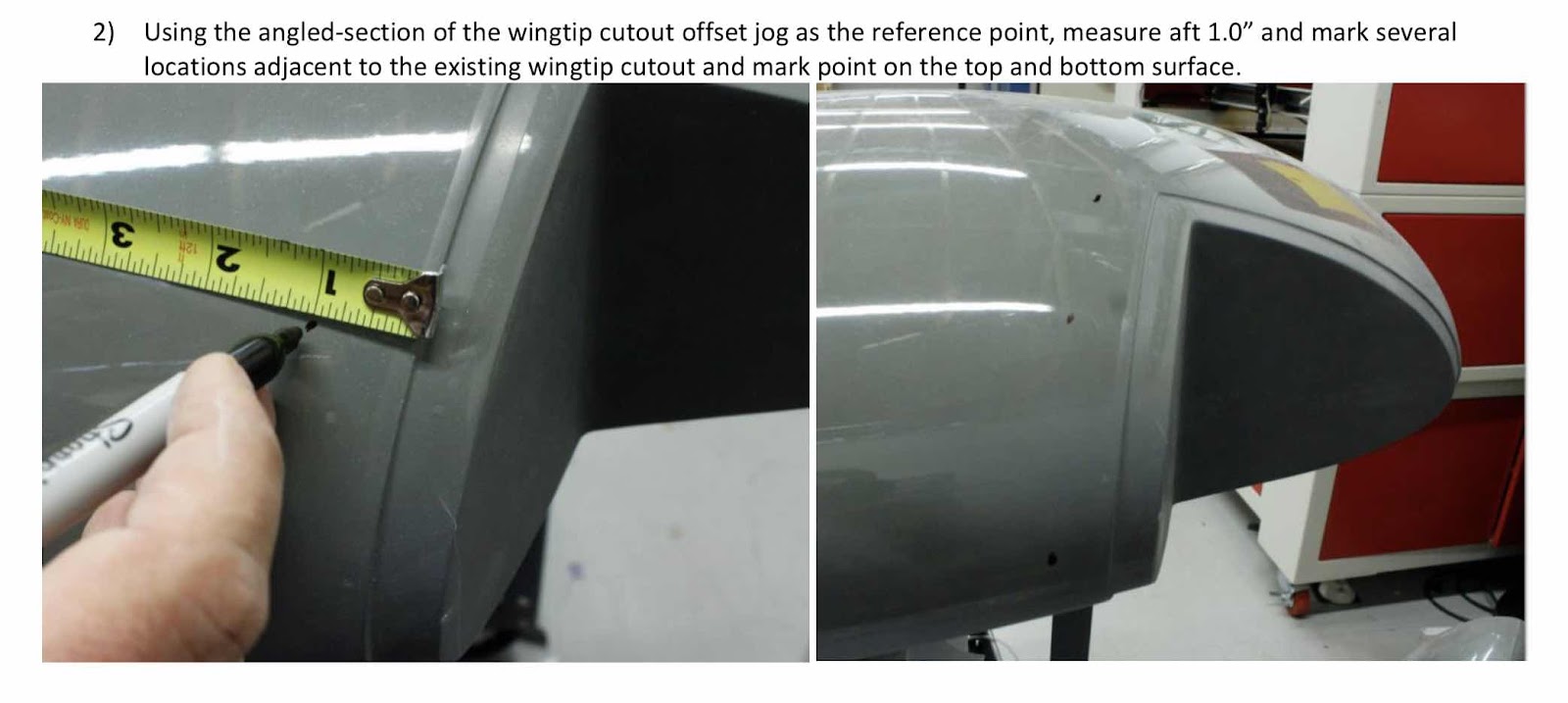
The first couple of steps (Steps 1 and 2 from the instructions) is to make reference marks at either 3.5” [88.9 mm] or 1” [25.4 mm] as shown in the plans excerpt below.


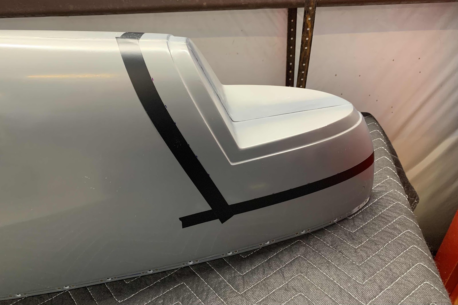
Once those reference marks were completed, we used electrical tape (or you could use fine line tape) to “connect the dots”.  Here are a couple of pictures of our Wing Tip Fairing after installing the tape.


After all the tape was applied (Step 3), a sharpie marker is used to trace the inside of the tape line.  I forgot to take a picture of our Sharpie lines, but here is an excerpt from the instructions showing what it looks like after the tape is removed. 

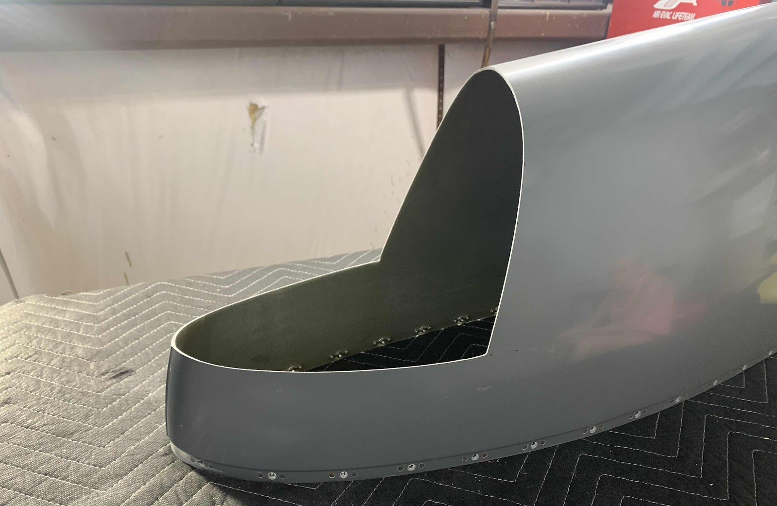
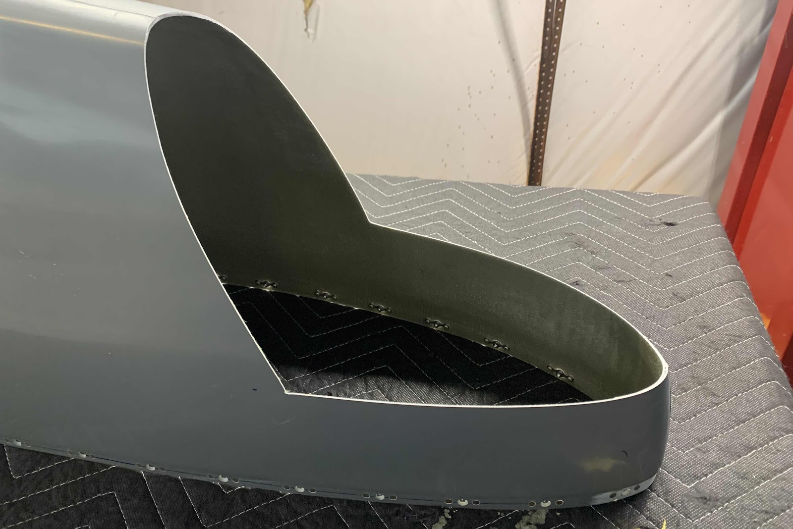
Next, I followed the instructions and used my Milwaukee rotary tool with a cutting wheel to cut just outside the sharpie lines.  After cutting out the area, here is a couple angles of what it looks like.  (I did use a sanding block with 80 grit sandpaper to smooth out the edges prior to taking these pictures)


The three pictures below show a couple of angles with the “new” inserted inside the Wing Tip Fairing.


If you look around the edges where the two pieces will join, you can tell the fit is not perfect.  Additional sanding will be required to get the desired fit between the two pieces.  (And ultimately some blending and filling to get the best possible result).  That is pretty much where we finished for the day.  We will pick it up from here during the next work session.

Thursday, October 1, 2020

Wings, Wing Tip (Part 10)

Alright, the Ribs have dried overnight and are ready to be installed in the Wing Tip Fairings.  I clecoed the Ribs into place on their respective Fairings and installed the rivets.  The aft three rivets on the top and bottom of each Fairing are MK-319’s and the rest are AN426AD3-3.5 rivets.   I used my gun and bucking bar to set the solid rivets and hand rivet puller for the MK-319’s.

The plans advise “When setting solid rivets in fiberglass composites, use soft rivets or leave normal rivets with a longer shop head (approximately 1.2 x the hole diameter)”.  I used solid rivets and followed Van’s guidance.

Here is the top of the right Fairing with all the rivets set.....

.....the bottom of the right Fairing.....

.....and the inside of the right Fairing showing all the shopheads.

Here is the top of the left Fairing with all the rivets set.....

.....the bottom of the left Fairing.....

.....and the inside of the left Fairing showing all the shopheads.


Wednesday, September 30, 2020

Wings, Wing Tip (Part 9)

In Part 6, we completed this work for the left Wing Tip Fairing.  Tonight, we will complete the work on the right Wing Tip Fairing.  We also used the same measurements from Part 6 to make our rivet patterns on this Fairing.  I marked the rivet pattern much better on this Fairing than the last, so hopefully it’s easier to understand (it was for me).  Here is the rivet pattern for the top of the Fairing.....

.....and the rivet pattern for the bottom of the Fairing.

The top of the Fairing after match-drilling.....

.....and the bottom of the Fairing after match-drilling.

After completing the match-drilling, we removed the Rib and inspected the rivet holes.....looks like our measurements also worked great for this Rib.

Lastly, the 19 holes (10 on the top and nine on the bottom) were countersunk for either an AN425AD3 or MK-319 rivet (more on the rivets during another session).  Here is the completed countersinking on the top of the Fairing......

.....and the completed countersinking on the bottom of the Fairing.

After completing the required countersinking, I treated the right and the left Rib with Alumiprep, Alodine and Akzo primer.  They are hanging up to dry and will be ready to install during the next work session.


Tuesday, September 29, 2020

Wings, Wing Tip (Part 8)

Today was a very LONG and productive day!  In previous work session(s), we completed the left Wing Tip Fairing up to the point of trimming the trailing edge of the Faring to match the trailing edge of the Aileron AND installing the “new” landing light insert (more on that in a later work session) for the AeroLED lights.  I started today by trimming the Fairing “flange” to the required 1/2” [12.7 mm]....I didn’t take any pictures after completing the trimming, but man look how fast I’m going.....
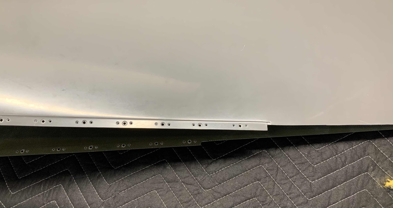


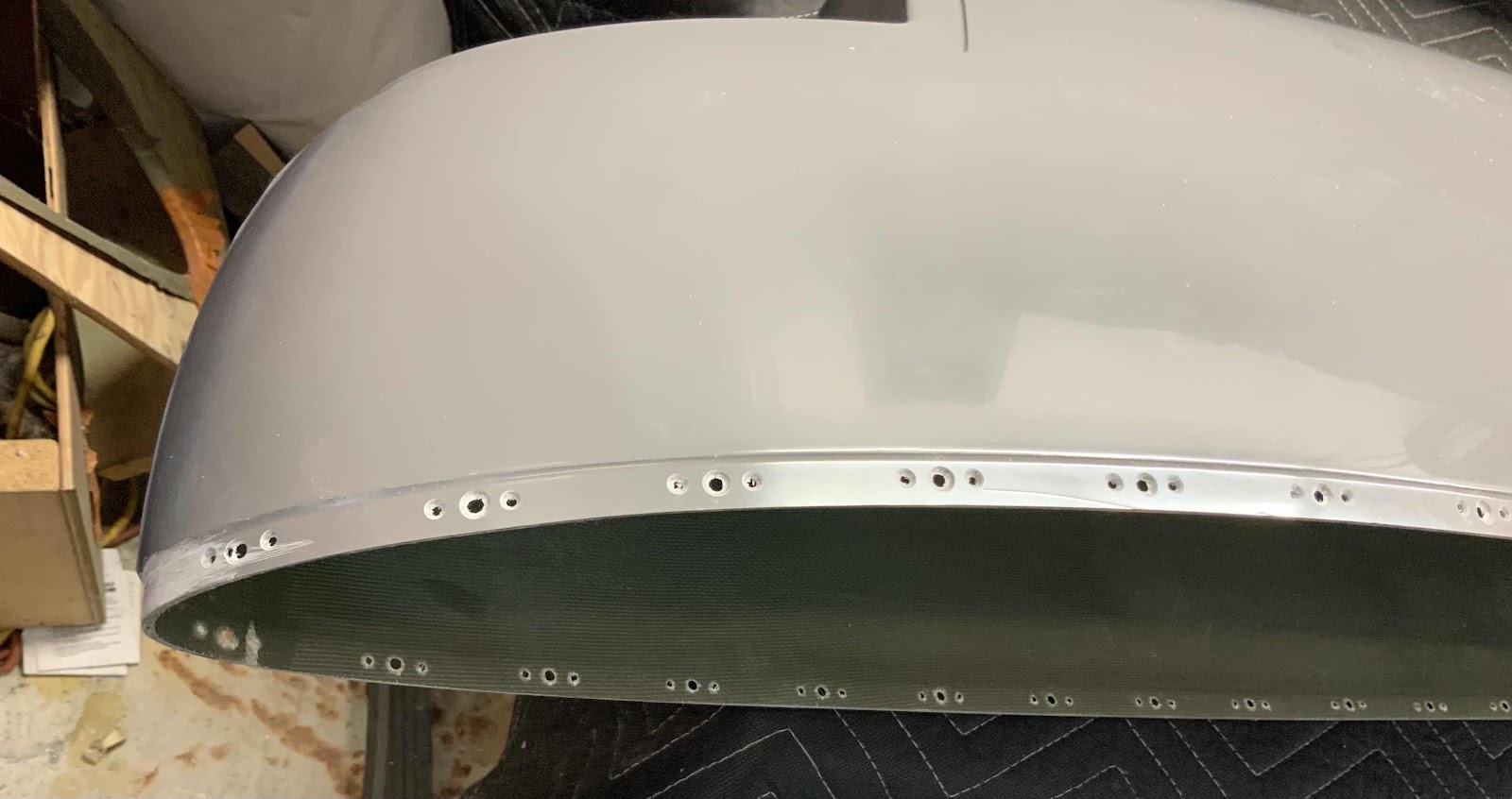
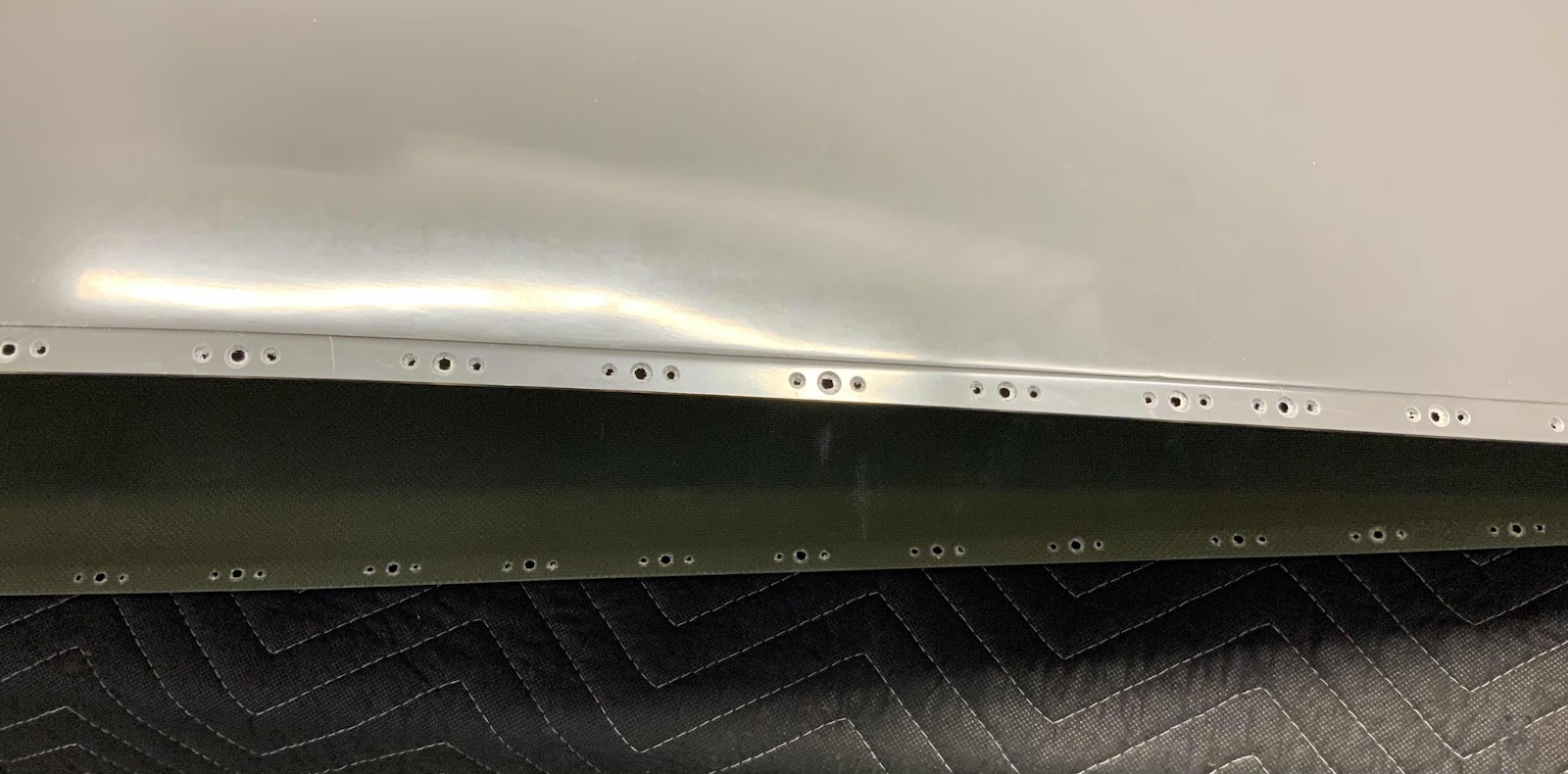
After the trimming was completed, the next step was to match-drill #40 the Wing Tip to the Wing (using the pre-punched holes).  The first picture below shows the completion of the match-drilling on the Top of the Wing.....

.....and on the bottom of the Wing.

Next, the Wing Tip was removed, the holes used as #40 drill guides were final-drilled #27, deburred and dimpled for a #6 screw.  Here’s the forward part of the Wing showing the dimples on the Top and Bottom Skins.....

.....and the aft portion showing the dimples on the Top and Bottom Skins.


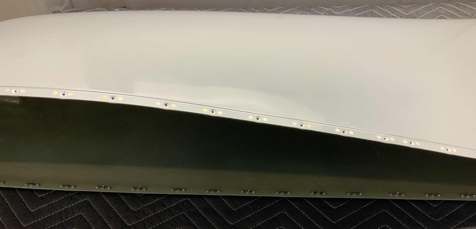
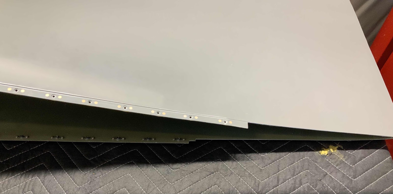
That essentially completes the preparation on the Wing itself.  Now, we’ll shift work back to the Wing Tip.  Just like with the left Tip, the right Tip also gets 42 K1000-06 nutplates installed on the Wing Tip flange.  To do this, use the center screw hole on the Flange and a K1000-06 nutplate to locate the nutplate attach holes.  The nutplate attach holes get match-drilled to #40 and countersunk to accept the head of an AN3426AD3 rivet.  The center screw hole also gets countersunk to accept the dimpled Skin from the previous step.  The following pictures show the completed process.....


All of the 42 nutplates have been installed using AN426AD3-4 rivets and the Wing Tip was temporarily screwed into place on the Wing.  Here is the right Wing tip with all the nutplates installed.


There is still a little bit of trimming required to complete the final fit.  I found it much easier to see what trimming was required with Tip actually installed on the Wing. This shows the clearance between the Tip and the Aileron in the down position.....

.....and in the neutral position.

I’ll complete the trimming during the next session.