Showing posts with label Section 40B-TD Gear/Engine Mount. Show all posts

Monday, June 14, 2021

Finishing, Tail Dragger Landing Gear and Engine Mount (Part 9)

The last part of this section was to install bolts into both the left and right sides of the F-01404 Aft Center Section Bulkhead Assembly.  Not much to show here, but there were:

(2) AN5-11A bolts (one on each side)
(6) AN6-12A bolts (three on each side)

The plans are straight forward and the bolts installed very easily, so nothing to really post about it.

SECTION COMPLETE!!!!!

Finishing, Tail Dragger Landing Gear and Engine Mount (Part 8)

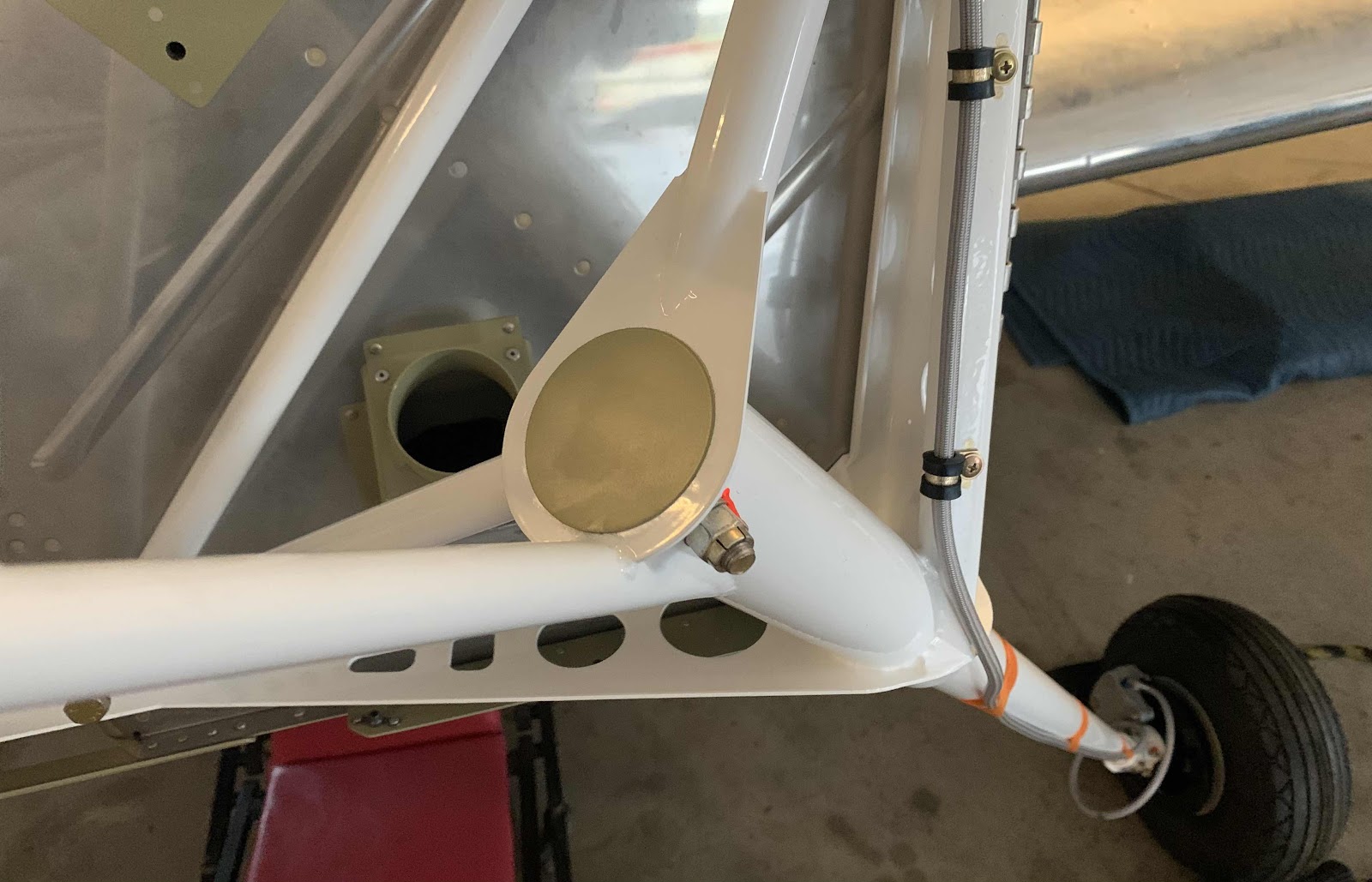
In this session, we installed the two U-01439 Gear Leg Caps.  (In Part #4, you can see what is underneath these Caps).  I prepared the two aluminum parts like all the rest.....sanded the edges, treated them with Alumiprep/Alodine and sprayed them with Akzo primer.

Once the primer on the two Caps was dry, they were installed on the Engine Mount as shown in the pictures below.  For the installation:

1.  The Caps were placed as close to the center of the hole on the Engine Mount as I could get them
2.  The perimeter of the Caps were traced onto the Engine Mount and removed
3.  Clear silicone was applied to the Engine Mount inside the traced circle (minus a small gap at the most bottom point of the hole - to allow expanding air in the Gear Leg to escape during ascent Van’s says)
4.  The Caps were then replaced and pressed into place


Finishing, Tail Dragger Landing Gear and Engine Mount (Part 7)

This work session was completed on May 3, 2021.

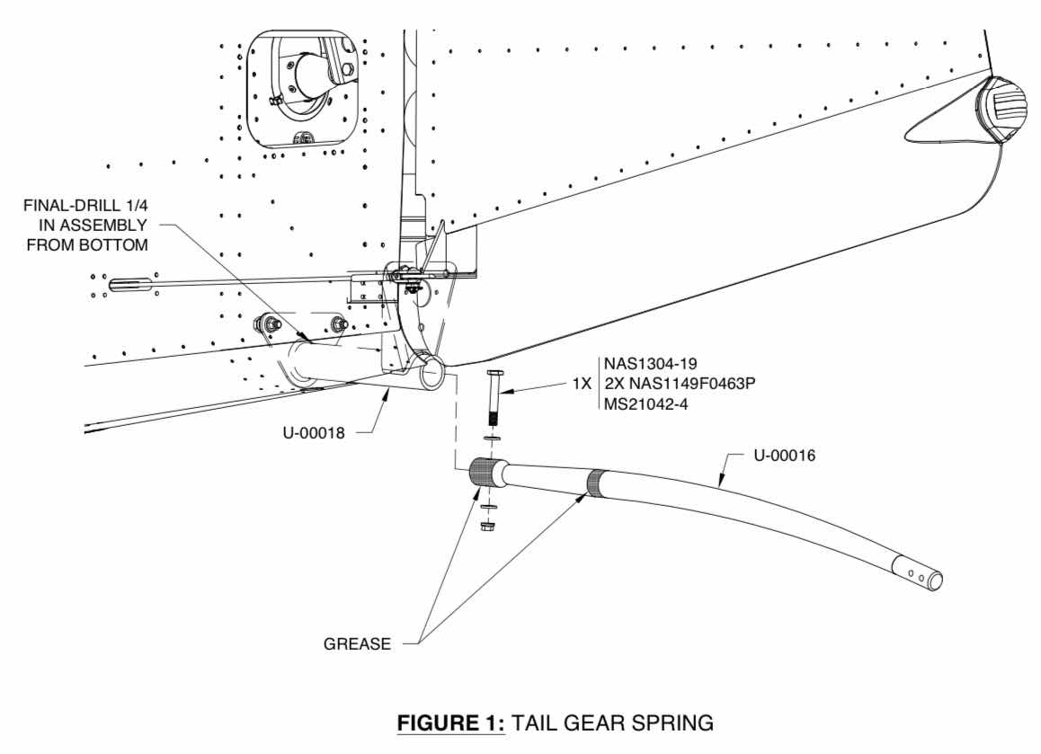
I thought I took several pictures during the fitting and installation of the Tail Gear Spring, but can’t find them if I did.  So, the only pictures I have are of the completed and installed Tail Spring.  The excerpt below shows the installation process for the Tail Gear Spring.
(Excerpt from the Van’s RV-14 Builder Plans)

The first step in the installation process was to clean the inside of the U-00018 Tail Gear Mount Tube and remove any surface rust, roughness or powder coating overspray with 400 grit sand paper.  In the excerpt above, the Tail Gear Spring needs to have grease applied in two specific areas.  In those areas, I also used 400 grit sand paper to clean those two mounting areas prior to installation.  The cleaning of Tail Gear Mount Tube and Tail Gear Spring with 400 grit sand paper was a process that took awhile.....sand, fit, sand, fit, sand, fit.....just like most everything else on the plane.  It took ALOT of sanding to get the two pieces to fit together properly.

Next, AeroShell Grease #5 was applied to the two areas on the Tail Gear Spring and it was inserted into the Tail Gear Mount Tube.  (I also applied some of the grease inside the Mount Tube).  A previously fabricated drift pin was inserted into the mounting hole (from the bottom), the assemble was clamped together with a C-clamp to prevent it from moving, the drift pin was removed and the undersized upper hole in the Tail Gear Mount was final-drilled to 1/4”.  Lastly, the NAS1304-19 close tolerance bolt and associated hardware was used to final install the Tail Gear Spring to the Fuselage.

Here is the completed and installed Tail Gear Spring and Tailwheel Assembly from the left side.....
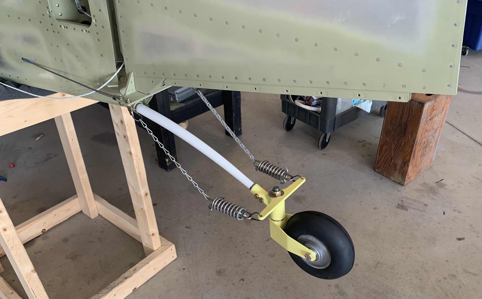
.....and the right side.

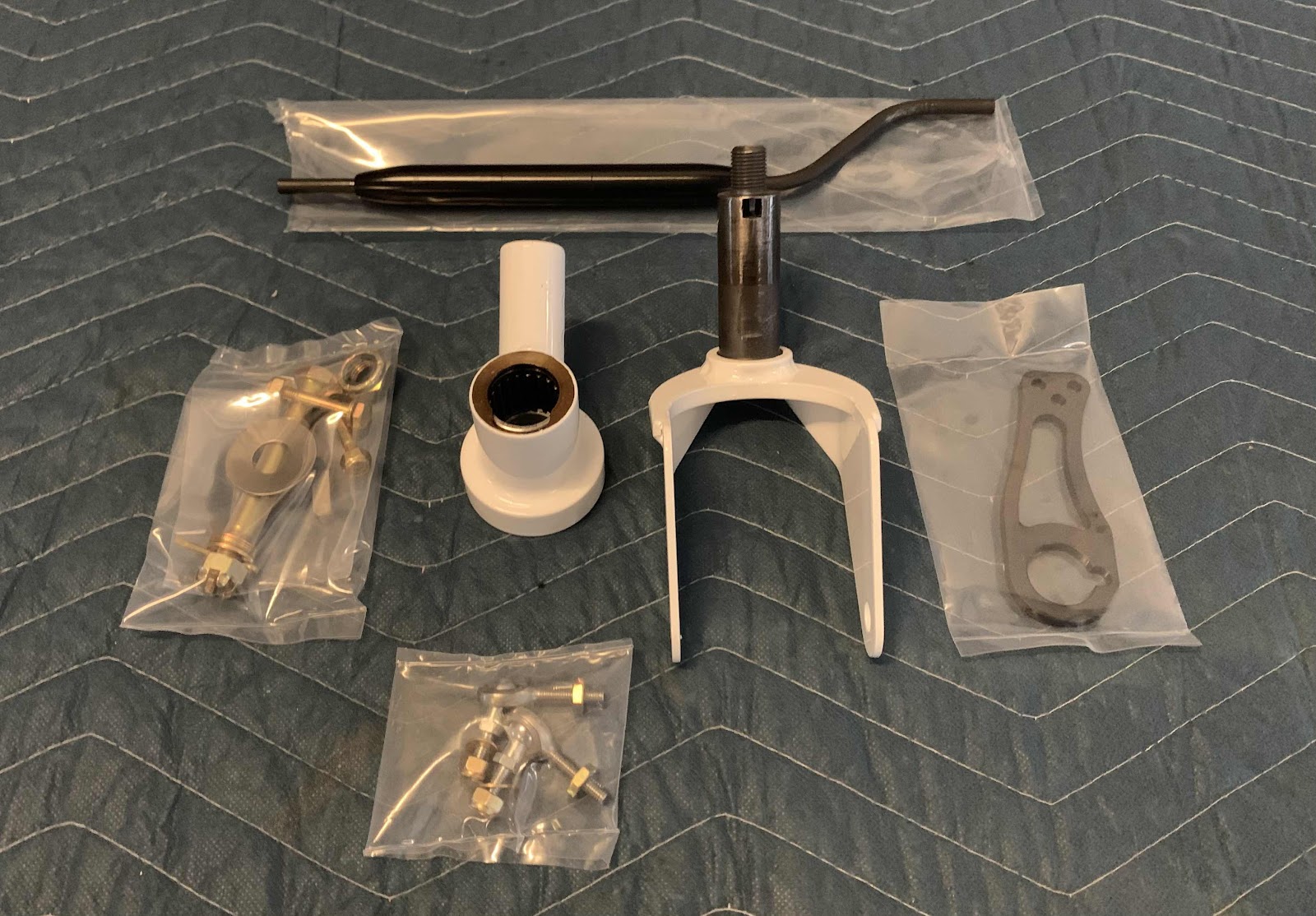
I also don’t have ANY pictures of the installation of the Tailwheel assembly, but it really doesn’t matter!  I will be removing the stock Van’s assembly and replacing it with the “RV-14 Tailwheel Assembly Including the Steering Link” (in white) from JD Air.  The picture below shows the JD Air assembly out of the box.  Just to be clear, there is absolutely NOTHING wrong with the stock Van’s assembly.....I just don’t like the springs and chains.  The JD Air version uses a steering link instead of the chains, so it’s a little cleaner installation in my view.

Please see the complete installation of this kit under Modification and Upgrades - Tail Wheel Assembly.

.....BUT FOR NOW......

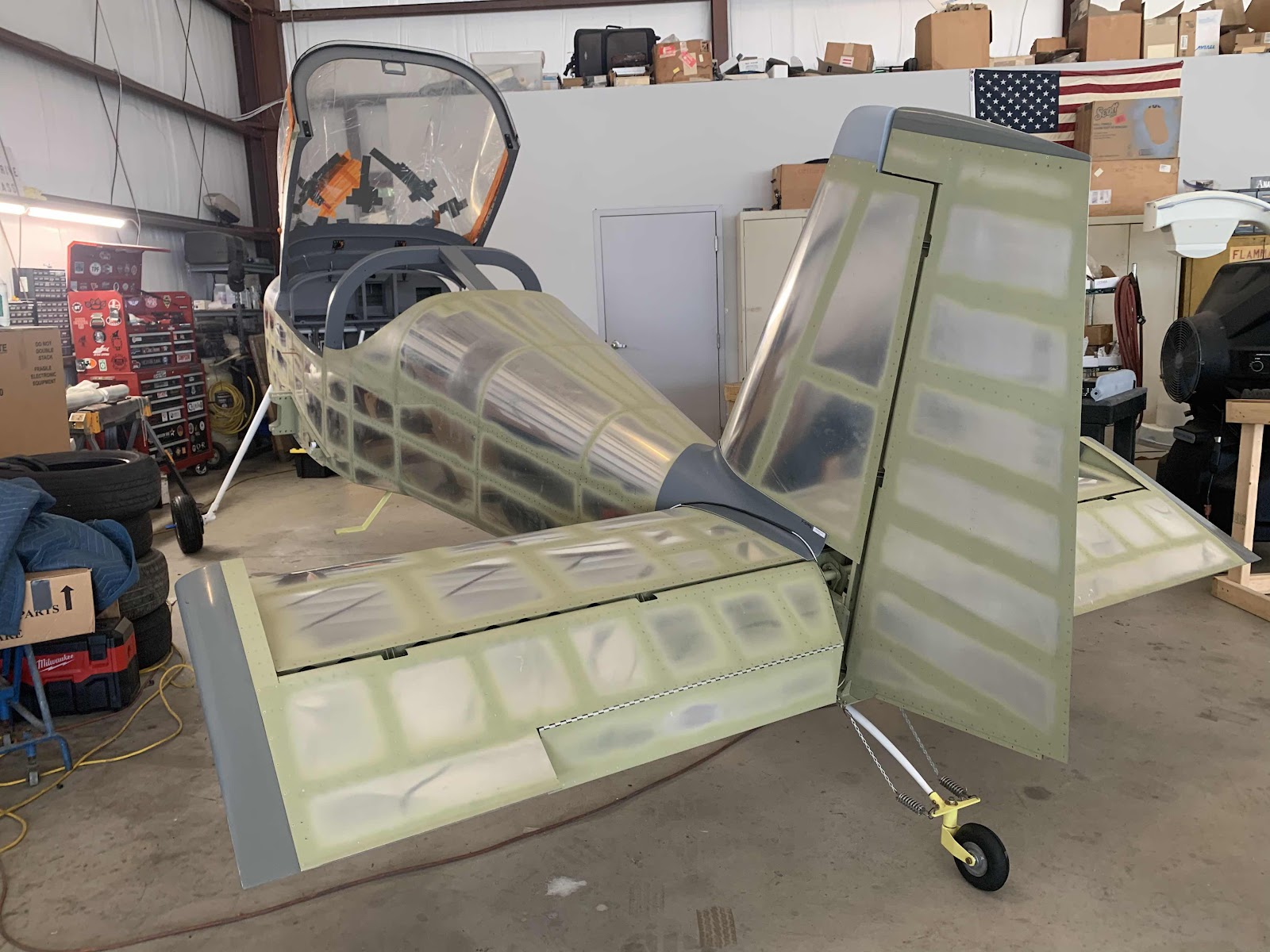
SHE IS STANDING ON HER OWN FEET FOR THE FIRST TIME!!!!!


Sunday, June 13, 2021

Finishing, Tail Dragger Landing Gear and Engine Mount (Part 6)

The work during this session was completed on May 7, 2021.

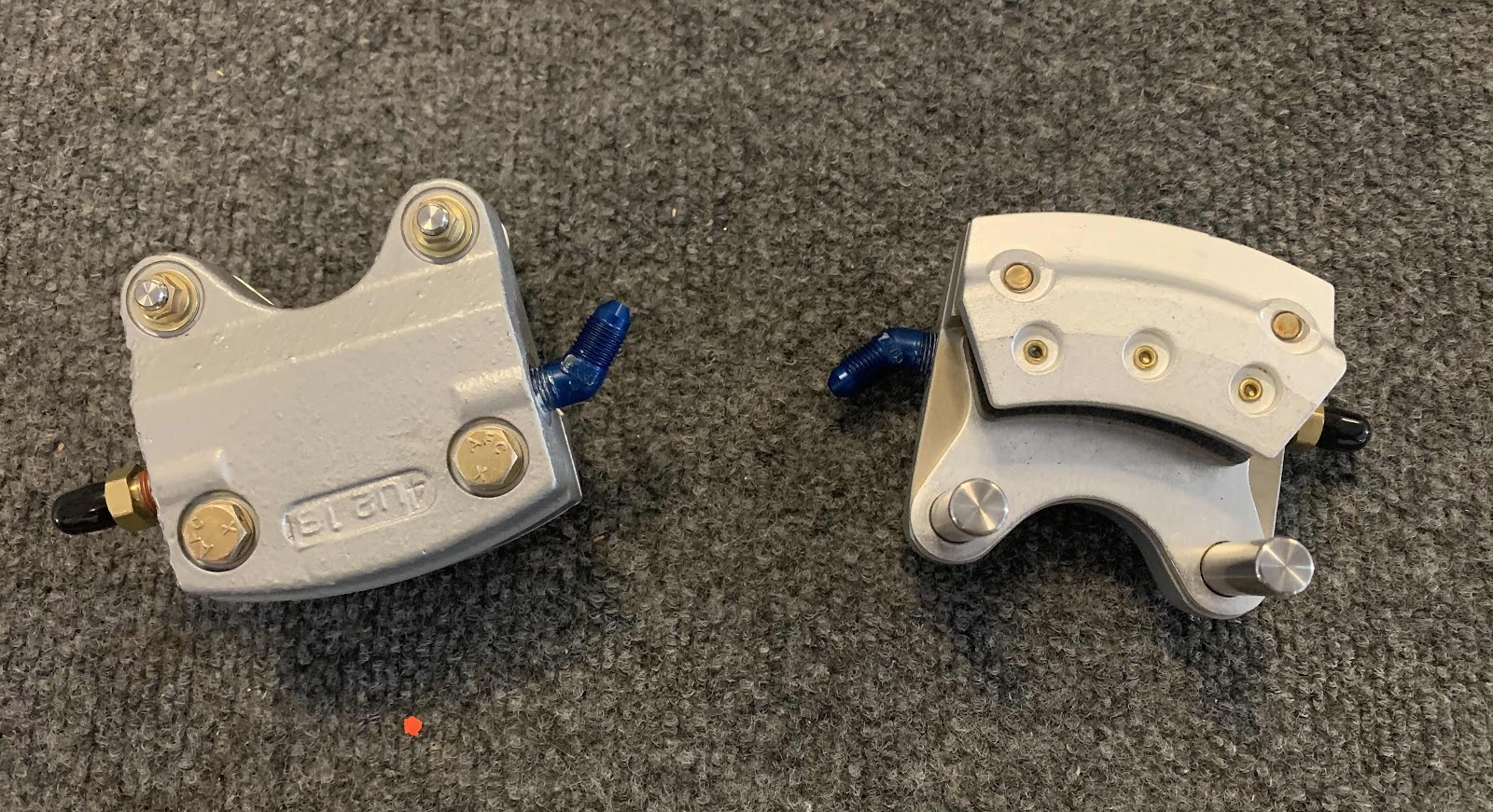
These are the U 55-204 Grove 5.00 x 5 Wheel Brake Caliper Assemblies.  Initially, we applied pipe thread sealant to the pipe threads of the blue elbows and installed them in the Brake Caliper body.  Here are the two Brake Calipers with the elbows installed.

To install the Brake Calipers, the two bolts were removed from each Caliper to allow it to be separate into two halves.....the back plate and the Brake Caliper body.  The back plate goes behind (outboard) of the brake disk, the torque pins get inserted into the brake torque plate and the bolts are reinstalled.  The process is the same for the left and right Brake Caliper Assembly installation.
(Excerpt from Van’s RV-14 Builder Plans)

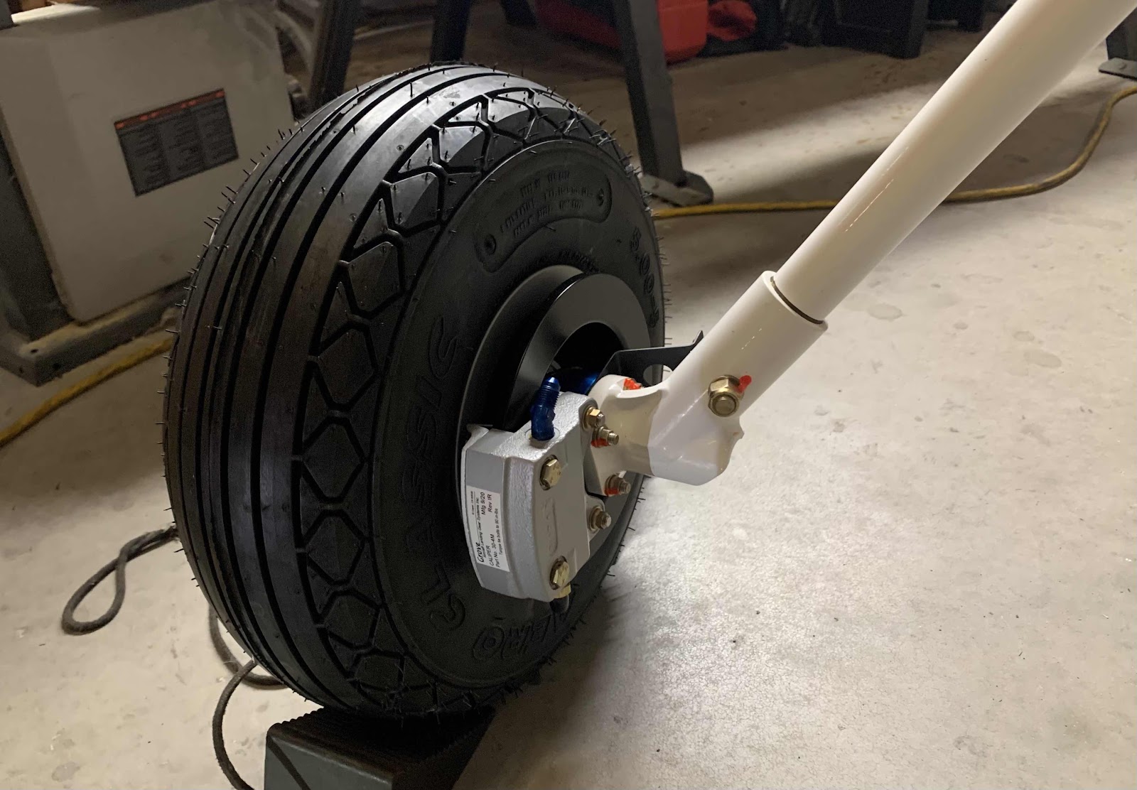
Here is the left assembly installed.....

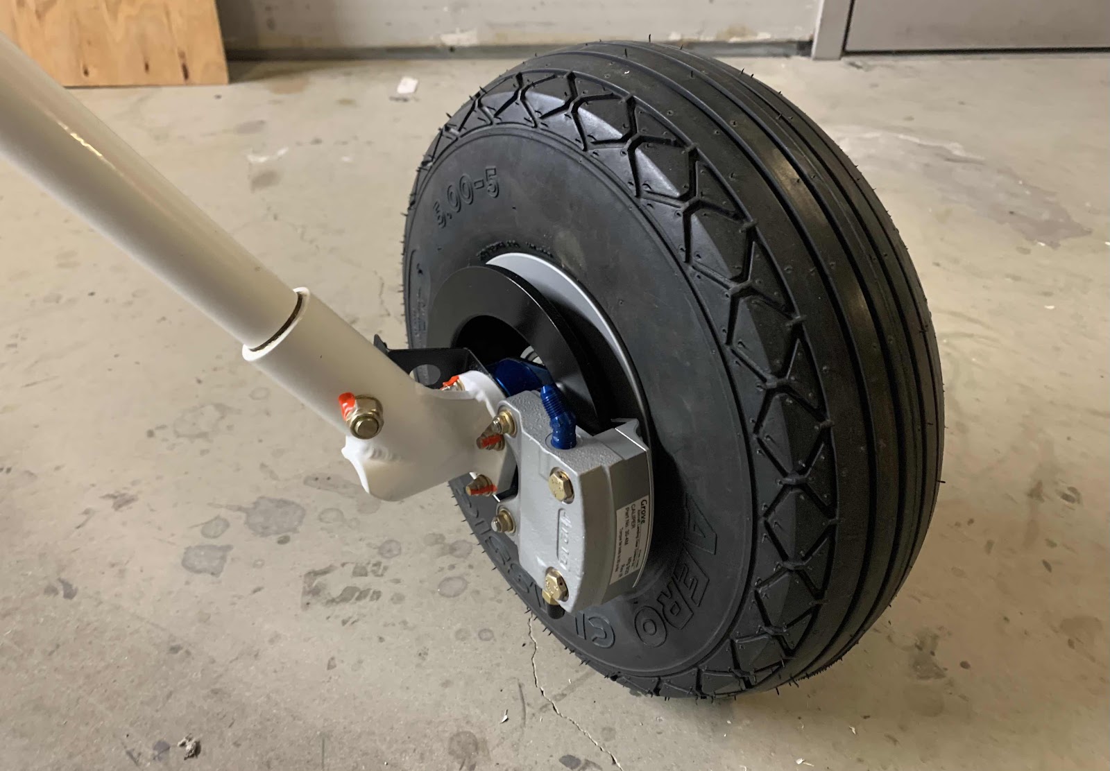
.....and the right assembly installed.

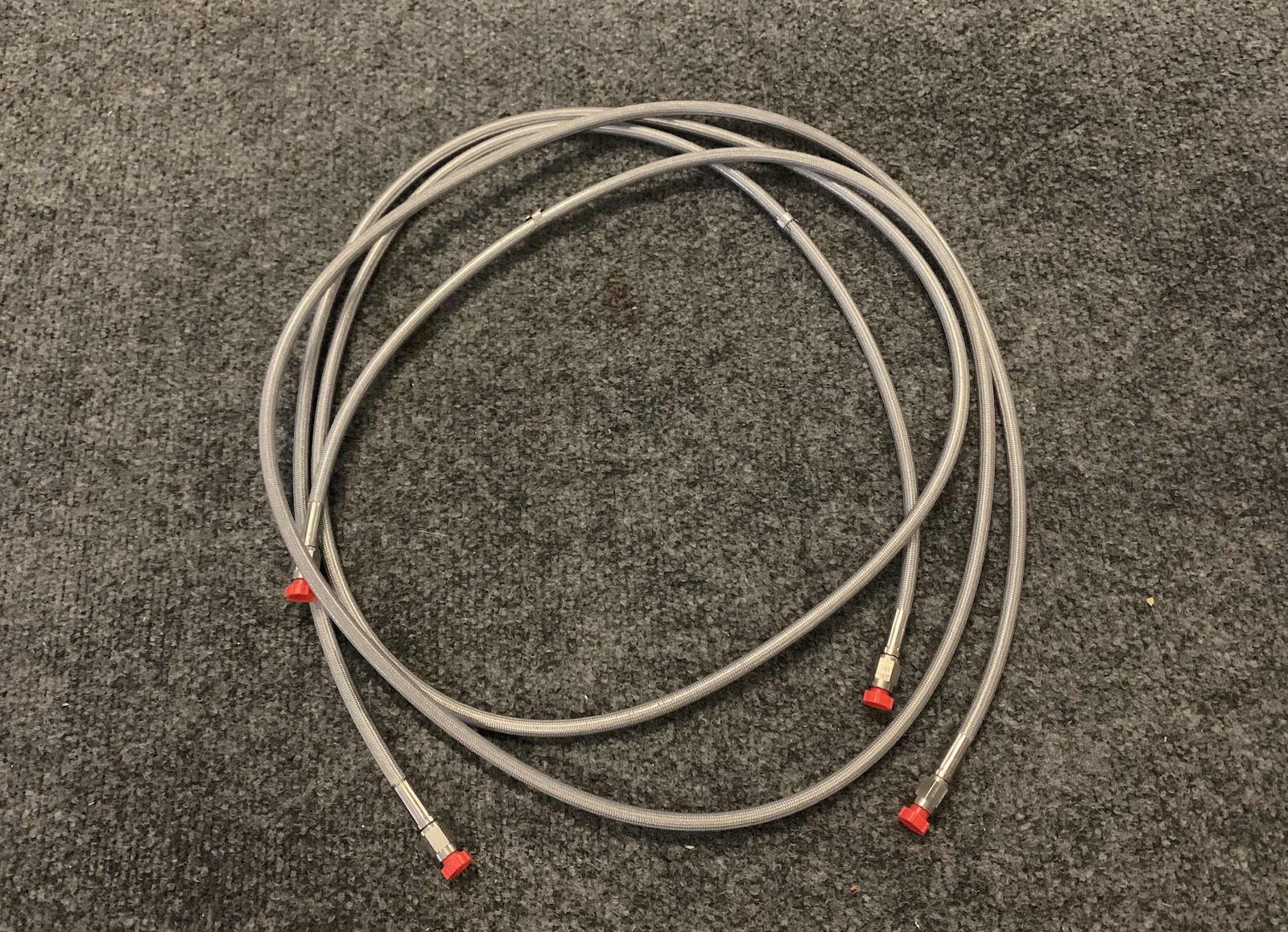
I decided to purchase aftermarket brake lines for the airplane.  I ordered the Gear Leg Hose Package from Aircraft Specialty.  (I have also previously purchased the Cabin Fuel Line and Cabin Stainless Braided Hose Kits.  Very high quality products and WAY better than anything I could make).  Pictured below is the Gear Leg Hose Package.

Here is the line installed on the right side of the Engine Mount....secured with two clamps and connected to the elbow in the Firewall.....

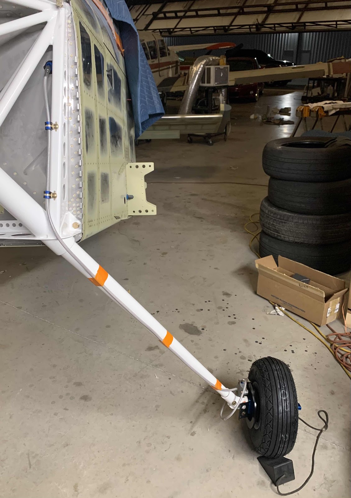
.....and “wrapped” around the Gear Leg and connected to the Brake Caliper Assembly via the previously installed elbow.

This is the left side installation on the Engine Mount.....

.....and down at the Brake Caliper Assembly.

The orange tape you see on the Gear Legs is just temporary to hold the line in position.  I will replace the orange tape with the proper “friction” tape prior to installing the Gear Leg Fairings.

Finishing, Tail Dragger Landing Gear and Engine Mount (Part 5)

This work session was completed on May 1, 2021.

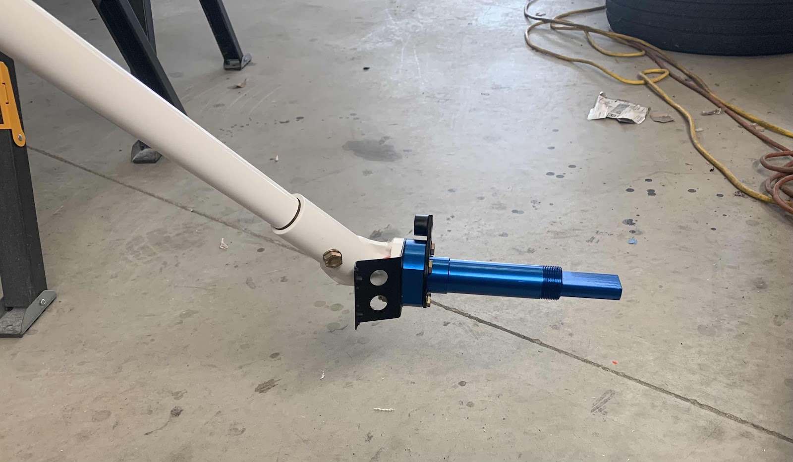
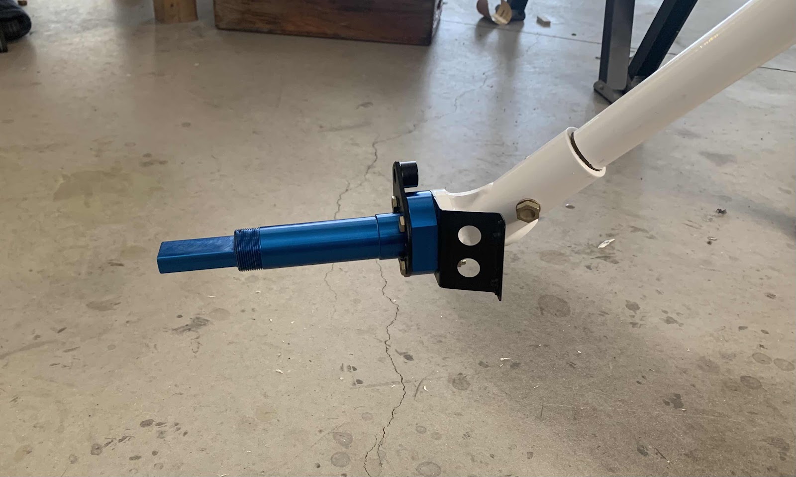
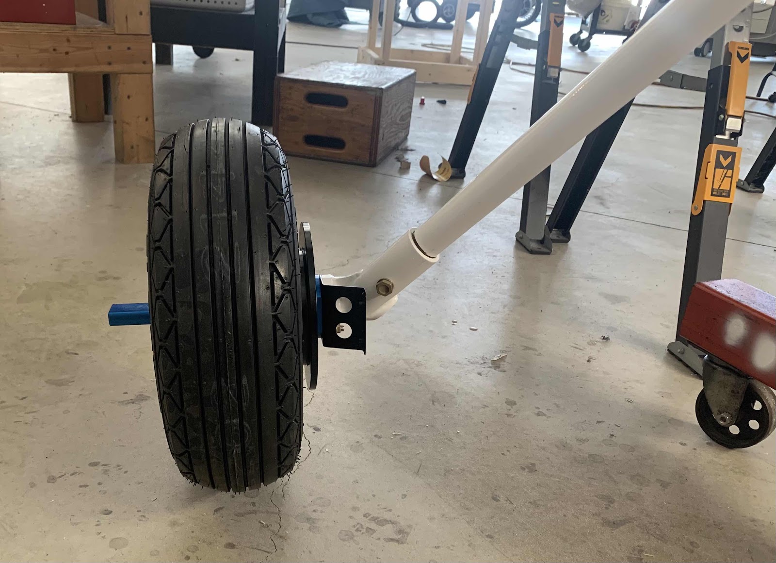
Now it’s time to install the U-00009 Axles (in blue).  There are a couple of parts that get bolted together with the Axles during this step.  The U-01418 Inboard Wheel Fairing Bracket (black piece on the left with the two holes) and the Brake Torque Plate (black piece on the right).  The whole assembly is held together using four NAS1304-21 close tolerance bolts.  This is the completed left Axle.....

.....and with the left wheel installed.

The same parts and pieces went into the assembly of the right Axle.  Here is the completed right Axle.....

.....and with the wheel installed.

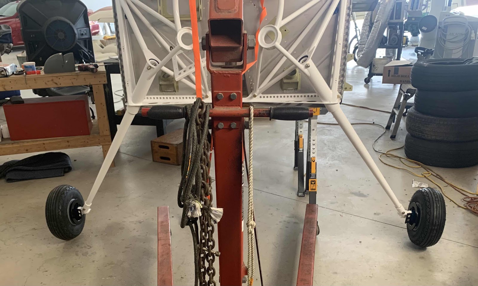
Just a head on picture with both wheels installed.  

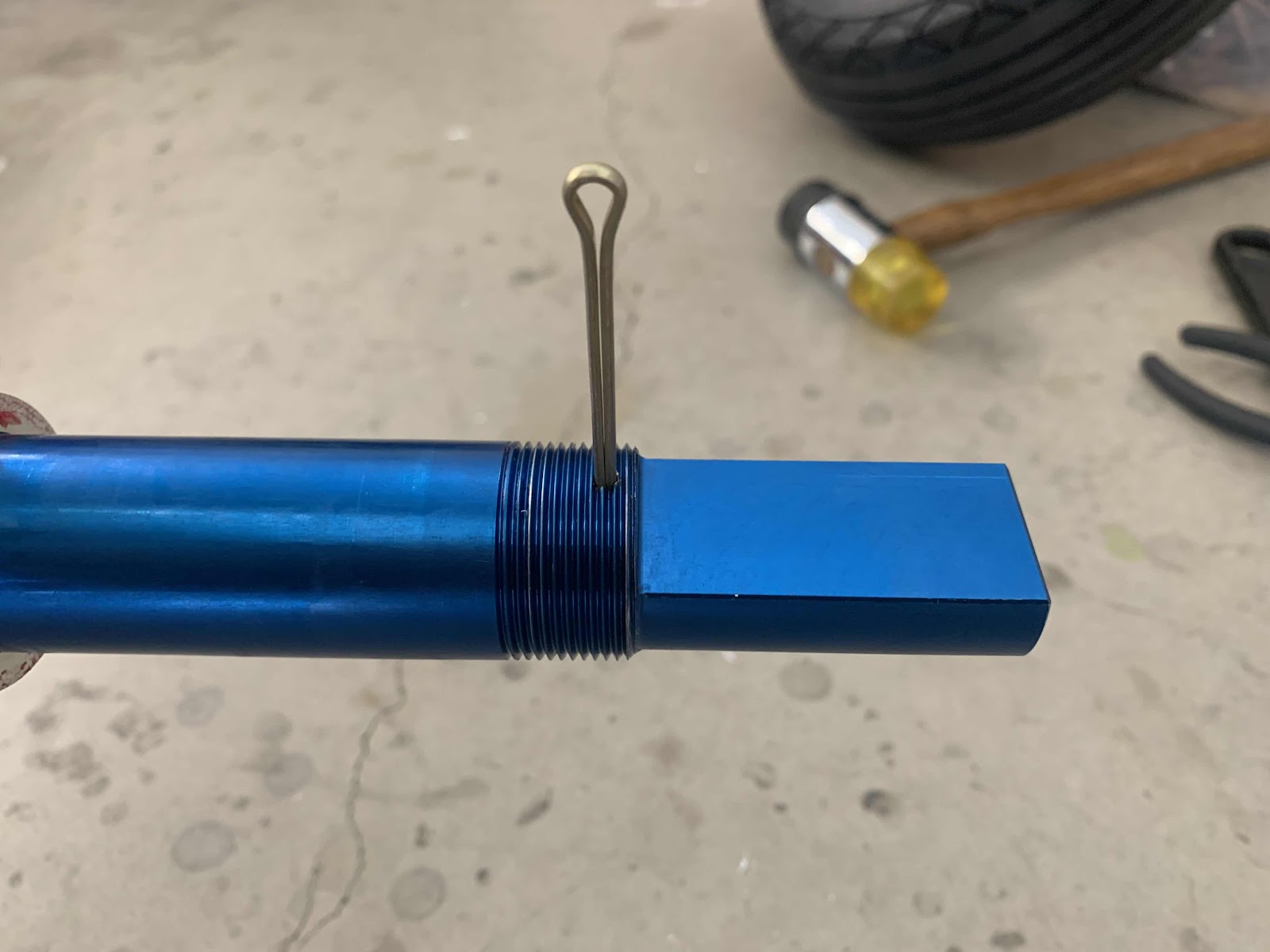
Now, I had an “issue” I had to call Van’s about.  In the picture below, the MS24665-359 cotter pin did not fit into the predrilled hole in the Axle....the cotter pin was to big or the hole was too small.  I wondered if it was the incorrect cotter pin size, mis-drilled during fabrication, etc.....so I called Van’s to inquire.  They didn’t really have any answers, as they haven’t run into this “problem” before.  One suggestion was to drill the hole out to 1/8th (correct size for the cotter pin), but I didn’t like the idea of “modifying” the Axle.  Another suggestion was to use a smaller cotter pin in the hole.  I didn’t like the idea of using a smaller piece of hardware than the plans called for during installation.  My A&P buddy Jeff said it was the right sized cotter pin.  So, what do I do?

I put a 1/8 drill bit into my drill and put the drill bit up to the hole to see the actual size difference.  I spun the bit (slowly with my hand) about a 1/2 turn and the drill bit went all the way through the hole!  Guess what?  Turns out there was a tiny burr on the hole from the manufacturing process the was stopping the cotter pin.  Once the burr was removed, the cotter pin also went right through the hole.  Much to do about nothing apparently.  So, the moral of the story here is.....check for a burr prior to installing your cotter pins!

After installing the Axles, the plans instruct you to verify the Axle alignment is correct by using a method they fully explain.  I have decided to wait until the airplane is finished (airframe, engine, prop, interior, panel, etc) to verify the toes.  The reason being.....to fix any out of alignment of the Axles, shims will have to be used to correct the error.  I would rather wait and correct any errors with the proper weight on the wheels.  I fell like I would get a truer result doing it this way.

Finishing, Tail Dragger Landing Gear and Engine Mount (Part 4)

This work session was completed on April 30, 2021.

With engine mount installed in the previous session, we can now put on some legs!!!!  

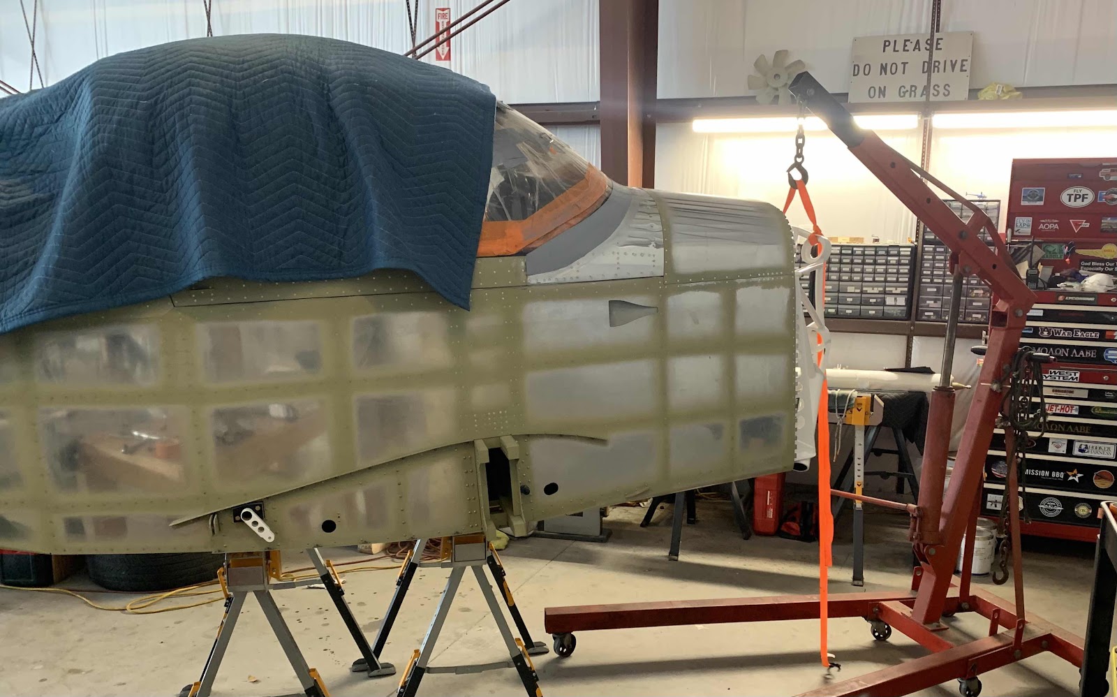
As it turned out, the sawhorses I had the Fuselage sitting on (for a long time) were to short to allow the U-01413 Main Gear Leg to be inserted into the FF-01401 Engine Mount.  So, I used and engine jack and some straps to lift it the extra height needed to clear the ground.  This picture shows what that looked like.  Even though the Fuselage was lifted by the jack and was clear of the sawhorses, I left them in place....just in case.....a six inch fall would be better than a two or three foot fall (I guess).

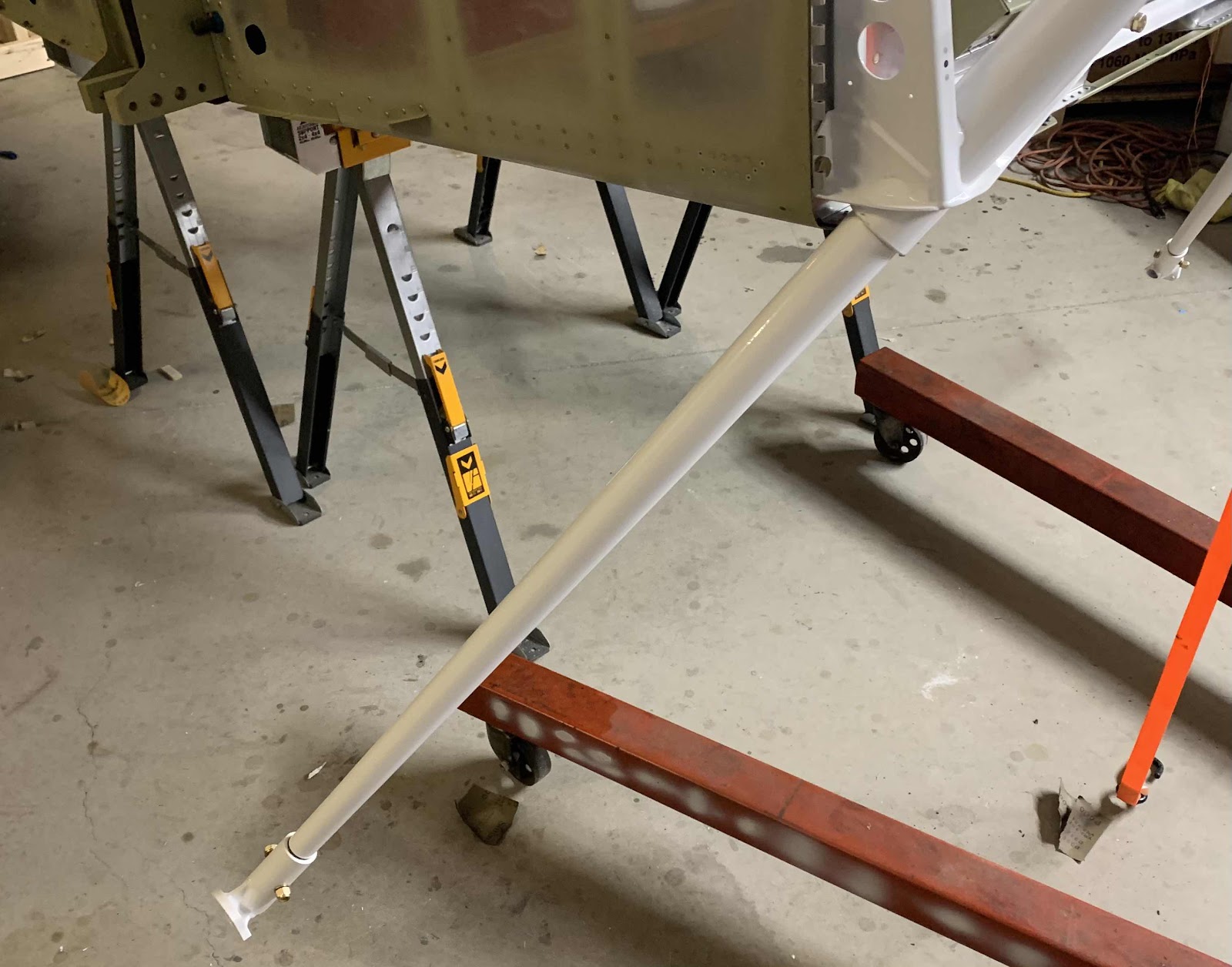
After following the instructions in the plans fabricating drift pins (to line stuff up), reaming holes (Gear Leg and Engine Mount) and applying grease (to areas not powder coated), the left Main Gear Leg is shown below final installed.  I was surprised at how easily the Main Gear Leg went into the Engine Mount.  After my “battle” with the tail spring, I guess I was expecting a harder time.  It fit perfectly.  At the end of the Gear Leg is the U-01421-L Gear Axle Fitting which is attached with only ONE (1) NAS1306-25 close tolerance bolt.  The Main Gear Leg is also only attach with ONE (1) NAS1306-38 close tolerance bolt to the Engine Mount.

Here is the right Main Gear Leg attached the same way as the left side.

This is the best shot I could get of both Main Gear Legs.  Getting closer to standing on its own two feet (or tires)!f

Finishing, Tail Dragger Landing Gear and Engine Mount (Part 3)

This work session was completed on April 30, 2021

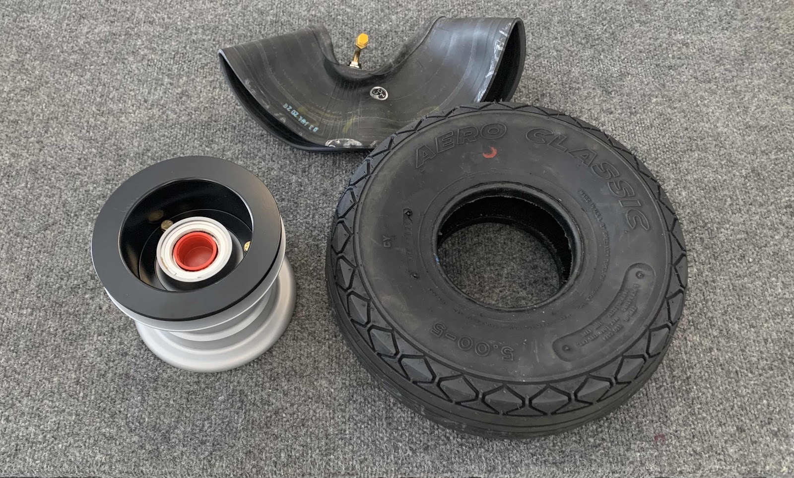
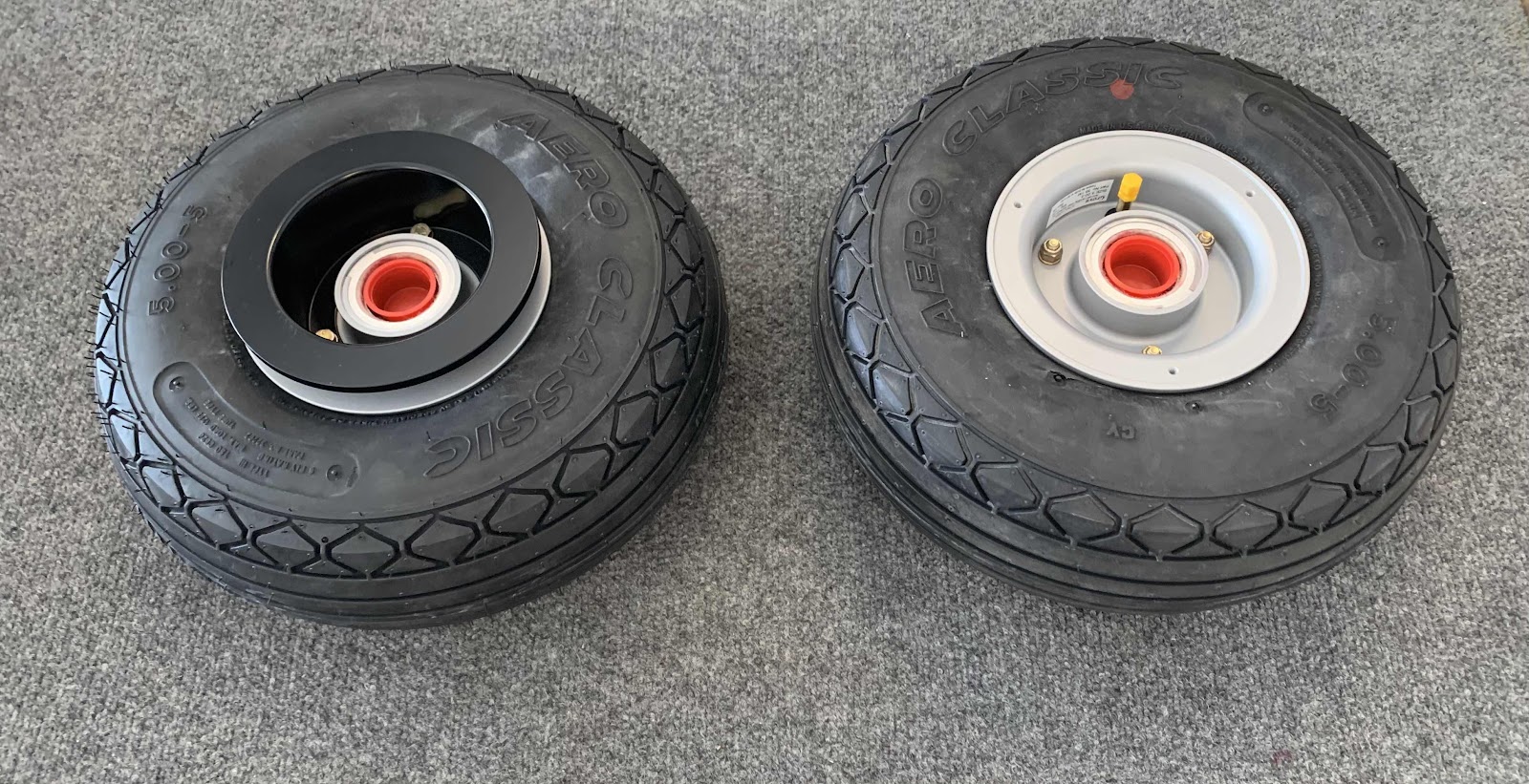
The next step in the process is the assemble the wheels and tires.  The three “pieces” for each Wheel Assembly came from Van’s in the Finishing Kit as shown below.  This was my first time doing this, so Jeff (my A&P buddy) showed me how to go it correctly.  The plans also provide VERY good instruction on how to do it also.

1.  U 55-204 Wheels from Groove Aircraft Landing Gear Systems Inc (x2)
2.  U 5.00x5-6 Aero Classic Tires (x2)
3.  U 5.00x5-6IT Inner Tubes (x2)


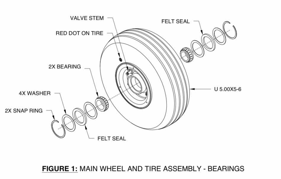
To begin, the bearings were removed from the Main Wheel Assembly as illustrated below (excerpt from the Van’s plans).  Once separated, I greased the bearings and re-installed them by reversing the step below.
(Excerpt from the Van’s RV-14 Builder Plans)

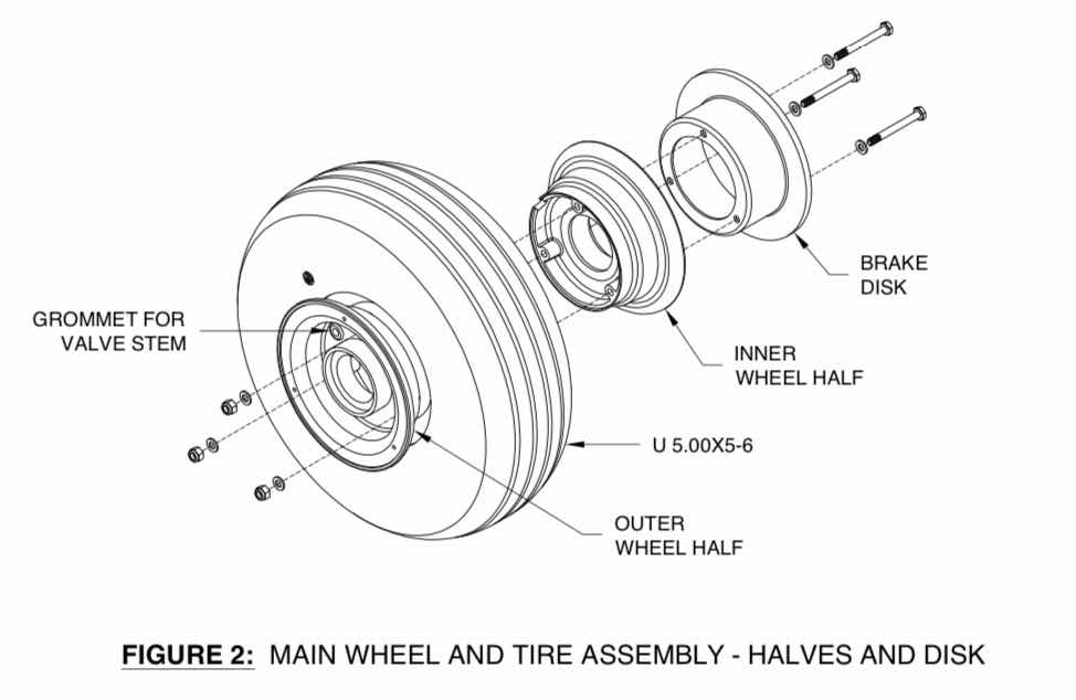
Next, the the Main Wheel Assembly was split in half by removing the three bolts holding them together as illustrated below (excerpt from the Van’s plans).
(Excerpt from the Van’s RV-14 Builder Plans)

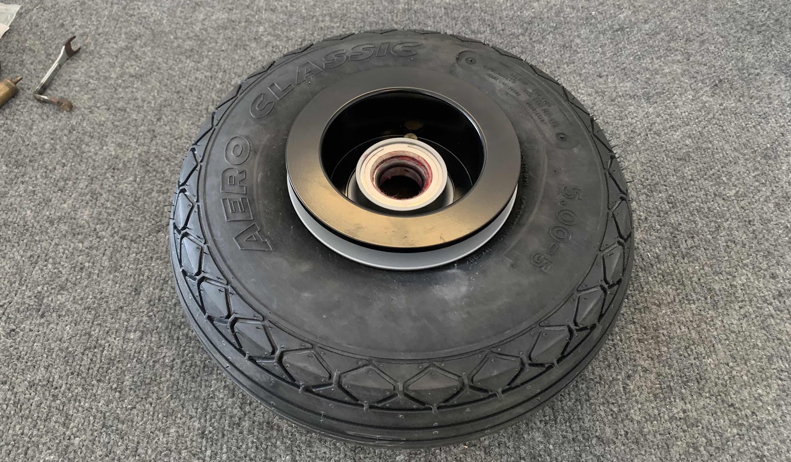
The Main Wheel Assembly was put back together with the tire and tube in place and torque to 90 in lbs (as indicated on the inside of one of the wheel halves).  The tire was inflated to 25 psi (and deflated) to make sure the tube wasn’t getting pinched and inflated to it’s final pressure of 40 psi.  Here is the “outside” of the completed Main Wheel Assembly.....

.....the “inside” of the Main Wheel Assembly.....

.....and both together.

Session Total:  1.5 / Tail Dragger Landing Gear & Engine Mount Total:  3.6

Saturday, June 12, 2021

Finishing, Tail Dragger Landing Gear and Engine Mount (Part 2)

This work session was completed on April 27, 2021.

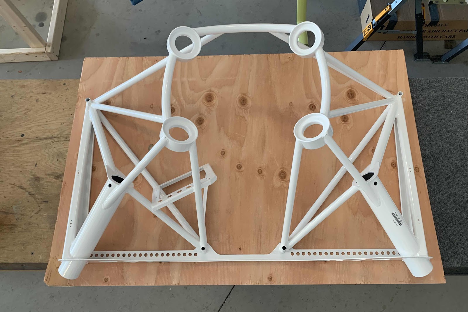
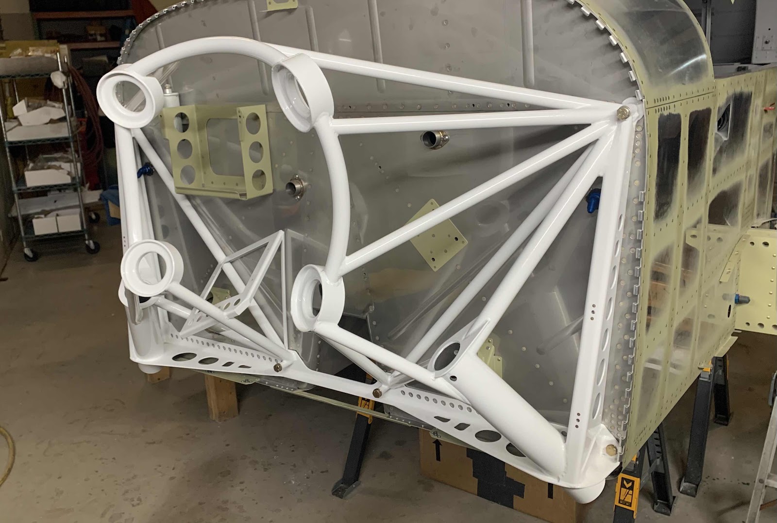
The Finishing Kit arrived on October 26, 2020; however, the engine mount was unfortunately on backorder.  On April 26, 2021, the engine mount FINALLY arrived.....ironically, it was exactly 6 months!  The engine mount arrived screwed to this sheet of plywood in a big cardboard box.
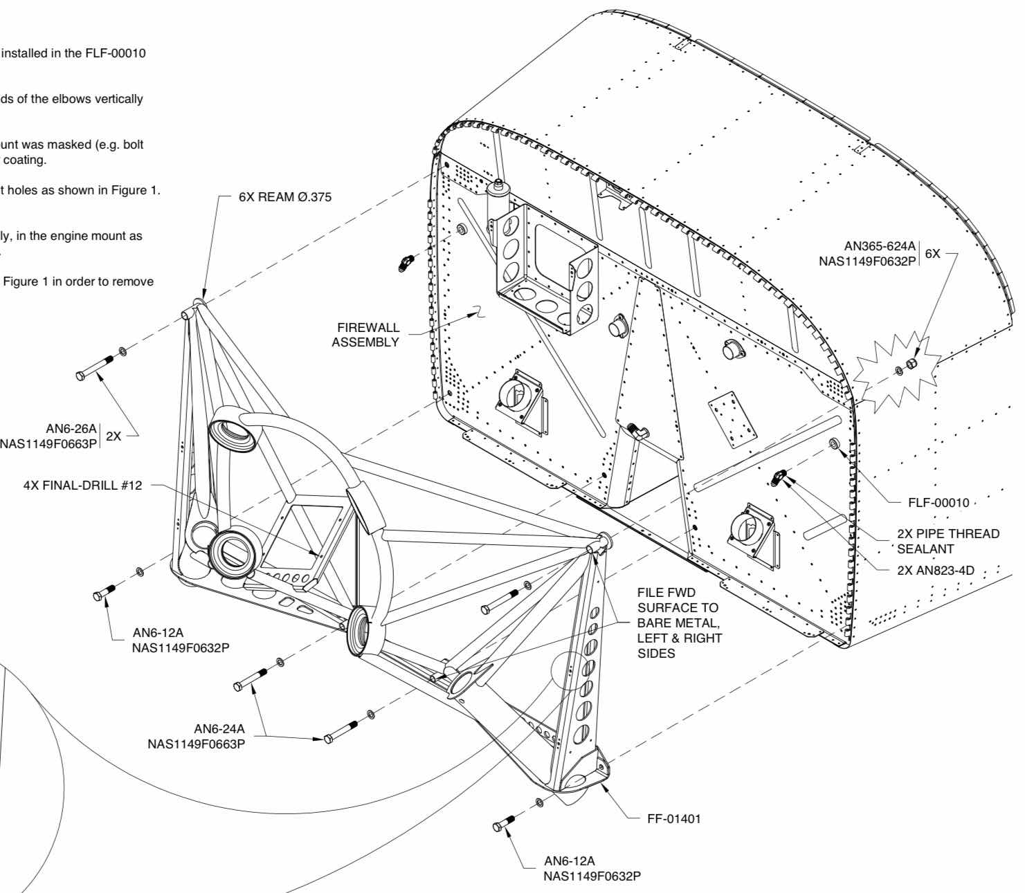
The first step was to install the two FLF-00010 Flanged Couplings on the Firewall.  These Couplings will be used for the hydraulics lines down to the wheel brakes.  After that, six AN6 bolts of various lengths will be used to attach the engine mount to the Firewall has described below.

(Excerpt from the Van’s RV-14 Builder Plans)

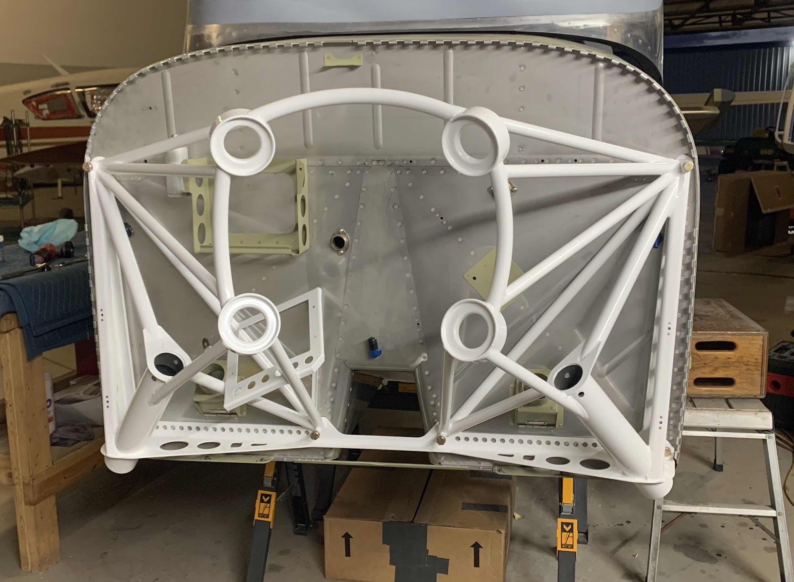
Here is the engine mount final installed to the Firewall.  This view if from the right side.....

.....straight on.....

.....and the left side.  The gear can now be installed during the next session.

Finishing, Tail Dragger Landing Gear and Engine Mount (Part 1)


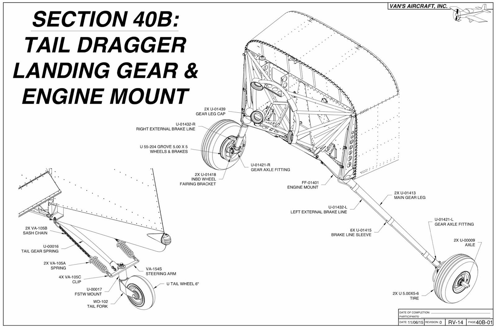
Section 40A, Tricycle Landing Gear and Engine Mount obviously covers the installation of the Landing Gear and Engine Mount on the tricycle RV-14A.  So, we will not be using this section for our tail dragger version RV-14.

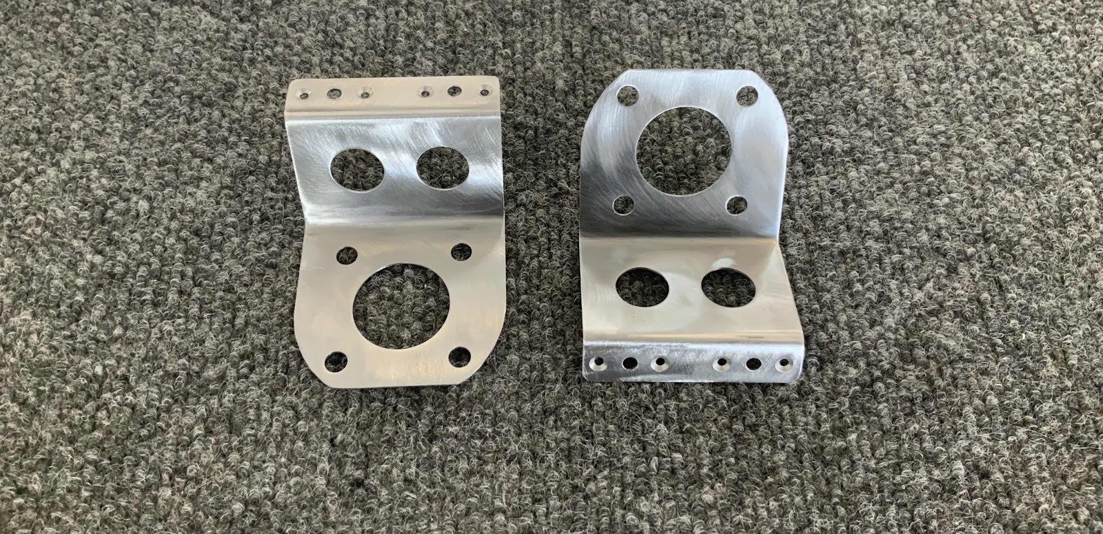
The two pictures below are the U-01418 INDB Wheel Fairing Brackets.  I had these parts for about three weeks before they started showing signs of corrosion.  So, I needed to remedy that problem.  The Bracket on the left shows the beginning of the corrosion I found and the Bracket(s) and the one on the right shows it after I cleaned it up.  I used my Angle Grinder and 2” Fiber Discs to remove the corrosion.

Here are both Brackets after being cleaned of all corrosion.  I also countersunk the four nutplate attach holes on each Bracket.  You can see the eight holes below on the Bracket flanges.