This blog was created to memorialize the building process of my Van's Aircraft RV-14 and to satisfy the requirements for certification in the Experimental Amateur Built Aircraft category. It will also serve as a central location for ME to reference in the future on processes and techniques I used during the build. Additionally, it will allow my family, friends, and other interested builders the opportunity to follow along during my build…..and might be helpful to someone along the way.
I let all the parts dry overnight following Akzo priming and now I’m ready to start riveting.
Below is an excerpt from the plans supplied with the Service Bulletin. This details the assembly steps for the Left and Right Aileron Hinge Brackets. Based on the plans, there are three different rivets used on this assembly. There are AN470AD4-11 (x3), AN470AD4-7 (x6), and AN426AD4-7 (x3) rivets used to assemble each Hinge Bracket.
These are the Left and Right Inboard Aileron Hing Brackets clecoed together.....
And after receiving the appropriate rivets.....
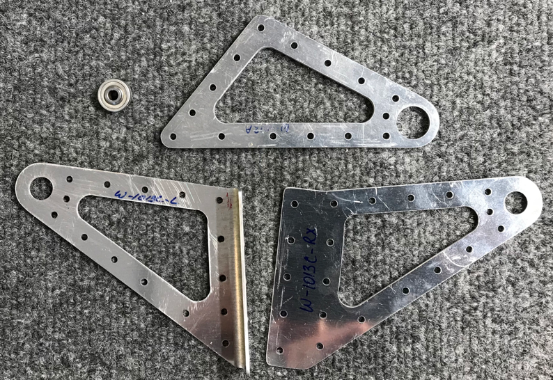
After completing the Inboard Hinge Brackets, I moved on to the Outboard Hinge Brackets. Below is the excerpt from the plans that details the assembly instructions. The first step is to “press” the COM-3-5 Bearing into the Doubler. The plans provided very good directions on how to accomplish this step. First, I used hand pressure to initially set the Bearing in the hole and make sure it’s going in straight. Then, as specified in the instructions, I used a 11mm socket (pressing directly on the bearing) and a 15 mm socket (pressing on the Doubler on the opposite side of the hole). After the Bearing and sockets were lined up, I used a bench vice to “press” the Bearing into position. This process worked out great. Once the Bearings are set correctly, they will stick out just slightly on both sides of the Doubler. The other two Brackets that complete the assembly have had a slight amount of material removed from the factory to accept the extruding Bearing. You can see this area on the W-1013C-LX piece in the diagram left of the Bearing.
This is a picture of the Doubler after the COM-3-5 Bearing was pressed into the Doubler.
And here is the Left and Right Outboard Aileron Hinge Assemblies clecoed together.
Tomorrow, I will rivets these two assemblies together with the rivets called out in the plans.
Finally.....I was able to get all the Inboard and Outboard Aileron Hinge Bracket parts and Rear Spar Doublers primed with Akzo during this session. Tomorrow I will start riveting the four brackets together.
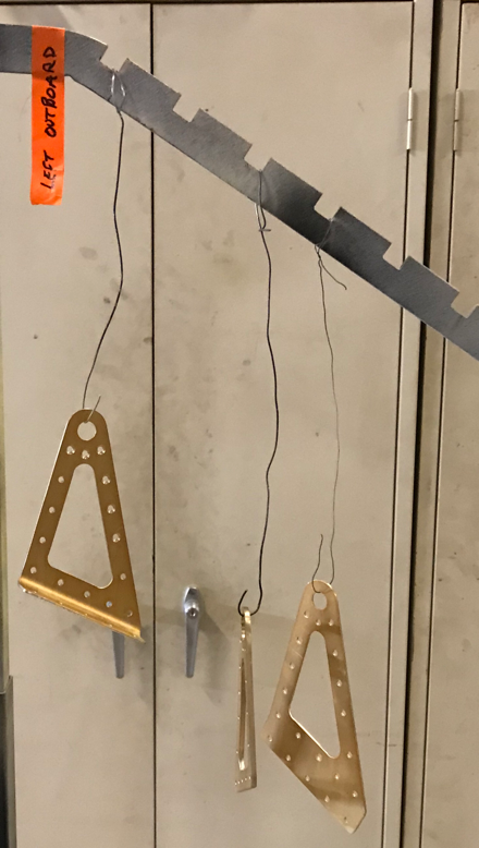
I was able to finish the Alumiprep and Alodine treatment on all the parts tonight. They are all hanging up to dry overnight and I will Akzo prime during the next work session.
Left Inboard Aileron Hinge Bracket Assembly.....
Left Outboard Aileron Hinge Bracket Assembly.....
Right Inboard Aileron Hinge Bracket Assembly.....
Right Outboard Aileron Hinge Bracket Assembly.....
I haven’t posted anything since January 3rd (Post # 4), but I’ve definitely been making small strides on the plane. I’m currently in the stage of preparing a lot of smaller parts/pieces and NOT showing any real physical progress! Lots of fitting, grinding, fitting, sanding, fitting, and sanding some more, etc. I haven’t posted those work session because there really wasn’t anything to see. However, with the work yesterday and today, I thought it was worth catching the site up.
Each of the Inboard Aileron Hinge Bracket Assemblies have seven pieces (14), each of the Outboard Aileron Hinge Brackets have 4 pieces (8), and three Rear Spar Doublers (3).....25 pieces total. Each piece needed some degree of drilling, sanding and edge work. So, I worked on these parts a little bit each of the last couple days.
These are the seven pieces that make up the Inboard Aileron Hinge Bracket Assembly. These parts were supplied as part of SB 16-03-28 for the reason discussed in a previous post.
These are the four pieces that make up the Outboard Aileron Hinge Bracket Assembly. These parts were supplied as regular Wing kit parts and are NOT associated with the SB.
I’ve shown the three Rear Spar Doublers in my previous post, but since I mentioned them again here.....here they are.
Here are the completed Left and Right Inboard Aileron Hinge Brackets. In the areas circled, both Angle Brackets had to be trimmed, filed and sanded to match the angle of the adjacent Side Brackets (Doublers). Here you can see the final product after I matched the two angles. Both of these Assemblies also needed the #30 holes to be final-drilled. The “fin” sticking up will serve as the Aileron stops once they are installed on the Rear Spar.
Additionally, the three holes in the Inboard Aileron Side Brackets were countersunk to accept the head of an AN426AD4-7 flush rivet (on the outboard side of the Bracket). In the picture below, the holes are marked 1, 2, and 3 on each piece. The remaining holes will receive AN470AD4-7 universal rivets.
As with the Inboard, the Outboard Aileron Hinge Brackets also had holes that were countersunk. You can see these holes marked below with 1, 2, 3, 4, 5, and 6. AN426AD4-7 flush rivets will also be installed these countersunk holes. AN470AD4-7 universal rivets will be installed in the remaining holes.
As I mentioned, this post encompasses work sessions over the last few days. Yesterday, I treated a few of the parts with Alumiprep and Alodine. Tomorrow, I will treat the remaining parts/pieces and they all will be ready for Akzo priming.
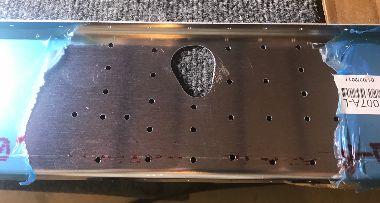
The picture below shows the “pre-punched” hole in the Left Rear Spar. This hole was used to trace the “blue line” on the Doubler during yesterday’s session.
This is the Rear Spar Doubler after I removed the material inside the “blue line”. I used a step drill to remove a large portion of the hole and a grinding bit in my angle grinder to trim right up to the “blue line”.
I re-attached the Doubler to the Rear Spar with cleco’s and used a fine hand file and 220 grit sand paper to match the Doubler hole to the hole in the Rear Spar. Here’s the final product and the two holes match up pretty well!
To finish tonight’s session, I deburred all the holes and completed the edge work on all three of the Doublers. They are now ready for Alumiprep, Alodine, and priming.
Today’s session started with drawing a parallel line at 5/16” from each edge of the four W-1007D Rear Spar Doublers (two on each Rear Spar) as shown below. I used my square to make the lines on each of the four Doublers and to keep them.....well, square!
The Rear Spar Doublers were aligned on the Rear Spar by nesting the upper flange of the Doubler underneath the upper flange of the Rear Spar and centering the line drawn above with the outboard-most row of attach holes as shown in the plans excerpt below:
The Doubler plate below (right in the excerpt above) was originally attached by aligning the 5/16” line and then clamping the Doubler to the Rear Spar. Once it was clamped in place, all the holes you see in the web were match-drilled (using the holes in the Rear Spar as drill guides) to #30. The holes in the flanges (where the silver cleco’s are installed) were match-drilled to #40. I installed clecos in each of the holes after match-drilling to aid in keeping the Doubler aligned correctly.
The Doubler plate below (left in the excerpt above) was attached using the same method as the first. However, you can see this plate is slightly different and missing several holes in the upper middle portion of the plate.
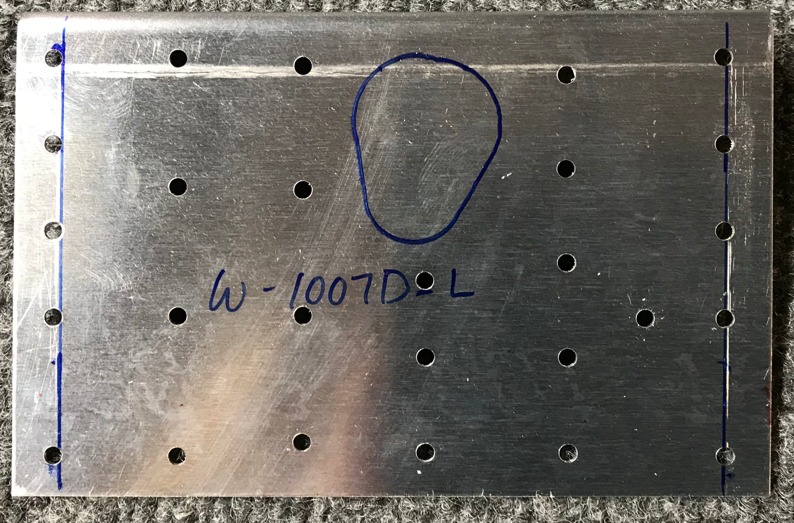
This is the opposite side of the Doubler shown above. The blue “shape” was drawn by tracing the same shaped pre-punched hole in the Rear Spar. The material inside the blue line will eventually be removed and sanded to exactly match the hole on the Rear Spar. In later steps, this hole will be used to allow the Left Aileron Pushrod to pass through the Rear Spar to Left Aileron.
This is the smaller Doubler plate of the three installed on the Left Rear Spar. This Doubler was aligned by nesting the upper flange of the Doubler underneath the Upper Flange of the Rear Spar and the Doubler with the outer edge of the Rear Spar. The web holes were match-drilled to #30 and the Flange holes were match-drilled to #40.....also, using the Rear Spar as drill guides.
I took a Christmas break to study the plans and Service Bulletin 16-03-28 to determine my next steps in the building process. Now that I understand what to do.....let’s do it!
Essentially, the assembly instructions (and parts) in the SB are to be substituted for the instructions in the plans (as they are currently written NOW).
The plans say that the manfacturing process leaves the W-1013 Aileron Hinge Bracket Spacers slightly warped or bowed and have to be straightened. My pieces were very slightly bowed, so I followed the directions and used firm hand pressure on the pieces while they were clamped in a bench vice. This process worked out fine and they are now pretty straight. The Spacers are shown below after being straightened as described above. The two Spacers on the right are for the Inboard Aileron Hinge (supplied in SB 16-03-28) and the two on the left are for the Outboard Aileron Hinge (supplied with the normal kit).
The next step was to prepare the the Aileron Attach Doublers. It came in one long piece and had to be divided into four individual pieces as described in the excerpt of the Service Bulletin below. I used my band saw to separate the four parts. These pieces will be attached on the forward side of the Rear Spar opposite the Aileron Hinge Brackets.
According to the SB, RV-14’s now skip to Step #20. Below is the figure associated with Step #20. The W-1013FG Aileron Angle Bracket also has to be separated into four pieces as shown below. The angle is separated at the three holes that are offset from the flange holes. There is a note that specifically describes the edge distance of two holes and their orientation in the assembly.
This is the raw piece of angle supplied with the SB.
You can see the offset holes described above and the blue perpendicular cut lines I have drawn using a square. The instructions say to cut perpendicular to the part and trim away any material the width of the holes across the entire part.
After cutting the pieces with my band saw, you can see where the offset holes were “cut in half” and will need to be filed and/or grinded smooth.
Here are the four finished pieces. I used a combination of a 6” Scotch-Brite wheel on a bend grinder, a fine hand file, and 220 grit sand paper. Once the pieces are all clecoed together with the Aileron Hinge Bracket, I can fine tune any edges that might need a little more sanding.
With the exception of some minor edge work, all the pieces that make up the Aileron Hinge Brackets have been prepared. Now, all the pieces are clecoed together.....keeping in mind the specific holes mentioned above requiring the appropriate edge distance.
Below are the two Inboard Aileron Hinge Brackets clecoed together. Like I said, a few of the pieces will need some additional edge work and two of the braces will need to be trimmed according to the excerpt above. After that, the pieces can be primed and riveted together.
The plans recommend that prior to assembling the Aileron Hinge Brackets, to refer to pages 15-01 and 16-01 to become familiar with the Brackets’ orientation as installed on the aircraft. Page 15-01 is shown above and page 16-01 is shown below. The two Aileron Hinge Brackets are circled in both pictures.
These are several Brackets that came in the kit. At this point, I am only using the two on the top left. The blue protective plastic has been removed and I used a blue sharpie to write on the part number.
These are the parts from the Service Bulletin (SB-16-03-28). I need to do some research to verify what needs to be done here, but I suspect the parts from the Service Bulletin will be used during this section of the build. The parts were accompanied by the documentation and assembly instructions. I’ll have to read the information contained in the packet and see where to go from here.
Since I am ending tonight’s session to research the Service Bulletin, I decided to cleco the Rear Spar onto the Wing to see how it fit. It looks pretty straight forward and fits as expected.....as usual, all the holes line up. There are several Rear Spar Doublers that need to be prepared using the Rear Spar, so it will have to come off during the next session. Like I said, I just wanted to see how it fit.
Below is the torque value chart from section 5.20 of the builders manual. The bolts used for the Wing Rib to Main Spar installation are all AN3 and use MS21042-3 Self Locking Nuts. As described below, you first need to determine the friction drag torque for the bolt/nut combination. Van’s tests showed an average friction drag torque of 14 in-lbs, but indicated results may vary. I also had a 14 in-lbs friction drag torque value, so I will use the same as Van’s. So, for the correct torque value, you take the friction drag torque value (14 in-lbs), the value shown in the chart (28 in-lbs), and add them together for a total torque value of 42 in-lbs. This bolt/nut combination will get torqued to 42 in-lbs. In Post #17, you can see an excerpt of where the bolts go and what orientation.
Wing Ribs #14, #13, and #12 do not utilize bolts (only rivets), so they are excluded for the time being. The plans state to cleco the W-1012-L & -R Outboard Wing Ribs and all W-1011-L & -R Inboard Wing Ribs (except the inboard most W-1011-R) to the Main Spar Assembly.....as shown in Step 1 below.
There is a note to NOT install the nuts and washers on the three most Inboard Wing Ribs (#1, #2, and #3) at this time. Additionally, in the second part of Step 3, it says “for the three most Inboard Wing Ribs, it will be necessary to push the bolt out of the way to set the rivets”. What rivets? It never specifically says in the plans, but it’s the small AN426AD3-3.5 rivets installed in the forward most hole in the forward tabs of the seven W-1011-L & -R Inboard Wing Ribs (Ribs #2 through #8).
The excerpt from above also shows the locations and size of rivets to install for the Wing Ribs and Main Spar. Most of today’s session was devoted to installing these rivets and I used the weapons below.....
Because of how the Wing Ribs are made , you are not able to get a straight shot on the manufactured head of the rivet. So, that is the reason I used the Offset Cup Set. I really don’t like using this rivet because it takes a few more hits to set the rivet.....because it’s offset. I personally also find it difficult to ensure the Set is square to the rivet head. I have to admit, I have a few “smiles”. I normally use my Sioux 2X rivet gun, but because all the rivets used are #4, I used my buddies 3X gun. The tungsten bucking bars are awesome! Get yourself one....or two.....you won’t regret the purchase.
There are 72 rivets that attach Wing Ribs #1 through #13 to the Main Spar Assembly. (Wing Rib #14 is only clecoed at this point and will be riveted later along with one of the Leading Edge Ribs). The vertical rows of rivets are the shop head for Wing Ribs #13, #12, and #11.
Here is where I deviated from the plans just slightly to complete Wing Ribs #1 through #4. Because they are so close together (wing walk area), it is difficult to get the rivet gun in between them. So, I removed Ribs #1 through #3 and riveted Rib #4. Then, clecoed Rib #3 and riveted, then #2, and then #1. This gave me plenty of room for the rivet gun and kept the Ribs out of the way.
Additionally, I previously did not rivet the Torque Tube Support Bracket Assembly to the most Inboard Wing Rib. If you follow this step in the plans and rivet the Assembly to the Wing Rib, you will not be able to get your rivet gun on the manufactured heads of the rivets from the Rib to Spar. So, I riveted Rib #1 to the Main Spar FIRST and then riveted the Assembly to the Rib.
The picture below shows the #1 Wing Rib riveted to the Main Spar and the Torque Tube Assembly riveted to the Wing Rib. You may notice that one of the rivets from the Assembly to the Rib #1 doesn’t look like the others. Ideally, you want the manufactured head of the rivet on the thinnest of the two pieces of aluminum. Again, because Ribs #1 through #4 are close together, you can’t get a rivet gun in there.
I used my pneumatic squeezer to set the very top and three middle rivets (pictured above and below), my had squeezer to set the very bottom rivet (pictured below.....assembly was flipped upside down), and the rivet gun/bucking bar to set the rivet in the opposite direction. Because of the Flange Bearing, I couldn’t get either squeezer on that rivet and had no choice but to set it the opposite way.
Anyway, Section 14 is now complete. Section 15 will be the Rear Spar and I will start there next time.