Wednesday, March 27, 2019

Fuselage, FWD/MID Bulkheads (Part 2)

*****Work during this session was completed on Friday, March 22, 2019*****

Today’s session was spent working on the F-01404 Aft Center Section Bulkhead.  To start, the #30 and #40 holes in the bottom flange had to be machined countersunk to fit a dimpled .032 Skin.  I used my .032 thick template with a dimpled #40 hole as a guide for the correct countersink depth. To hold the Bulkhead in place while I countersunk the holes, I clamped the Upper Flange to my workbench as shown below.  This allowed a somewhat steady base to complete the countersinking.

Here are examples of the #30 and #40 holes after being countersunk.  I put the orange tape on the Bulkhead to prevent pieces of aluminum shavings from getting in the seam.  I learned this lesson earlier when working on the Wing Spar.  Some of the little shavings are very difficult to remove once they are in the seam.  The tape keeps this from happening.

The next step was to countersink the #40 holes in the Upper Flange of the Bulkhead to fit the head of an AN426AD3 rivet.  These rivets will be attaching nutplates to the flange.  Here are three of the nutplates locations with the countersunk #40 holes.

The last step for today’s session, was to countersink the two #40 holes in the F-01404D-L & -R Side Angles.  Here are both of the Angles (-L on top and -R on the bottom).....

.....and a close up of the two countersunk holes on the -R Side Angle.


Wings, Wing Tip (Part 1)


As with all the other fiberglass pieces, I plan on completing them all at once near the end of the build.  More to follow.....

Wings, Aileron Actuation (Part 1)


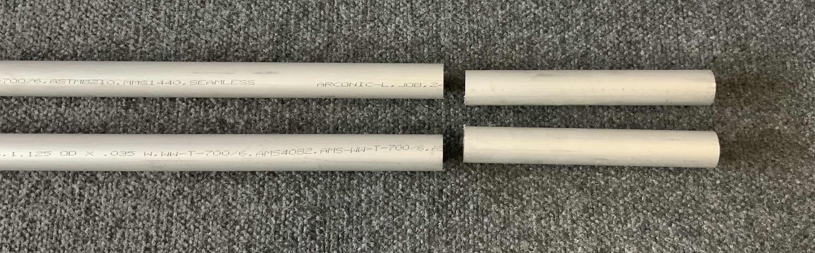
During today’s session, I started work on Section 23, Aileron Actuation.  To start, the two CS-00012 Torque Tube to Bellcrank Pushrods had to be fabricated from AT6-035 x 1 1/8 to a length of 64 1/4”.  Each Pushrod had to have a little cut off the end as shown below.  I was able to use my bandsaw the make these cuts.

Each end of the Pushrods will get Threaded Rod Ends installed, so each end had to have rivet holes drilled in them.  The template supplied by Van’s is shown below.....in several pieces.  I found that the template didn’t fit completely right.  Maybe it was something I did, but I couldn’t get the alignment holes on the template to....well, align with each other.  

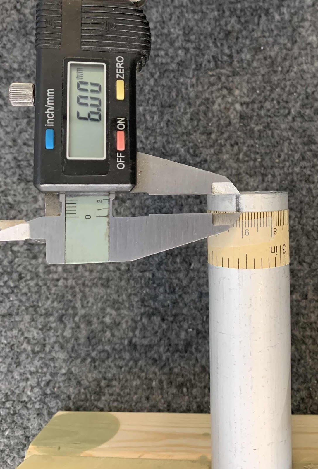
So, I decided to try something different.  I got a paper tape measure and wrapped it around the Pushrod.  I found the length to be 90mm.  According to the template, six rivets will be used on each end to attach the Threaded Rod Ends.  So, I divided 90mm by 6 and got each rivet location of 15mm.  I then measured the distance of 6mm from the rivet locations to the end of the Pushrods.  

Here is my template measred at 6mm from the end of the Pushrod.....


.....and here are three of the rivet locations marked at the 15mm spacing.

Next, all six of the marked rivet locations had #40 pilot holes drilled.  Here are a couple of the holes after being drilled.

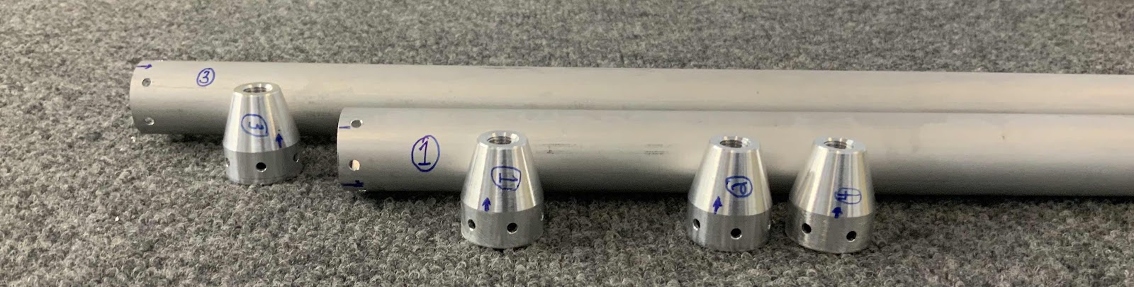
These are the four Threaded Rod Ends that will go in each end of the Pushrods.

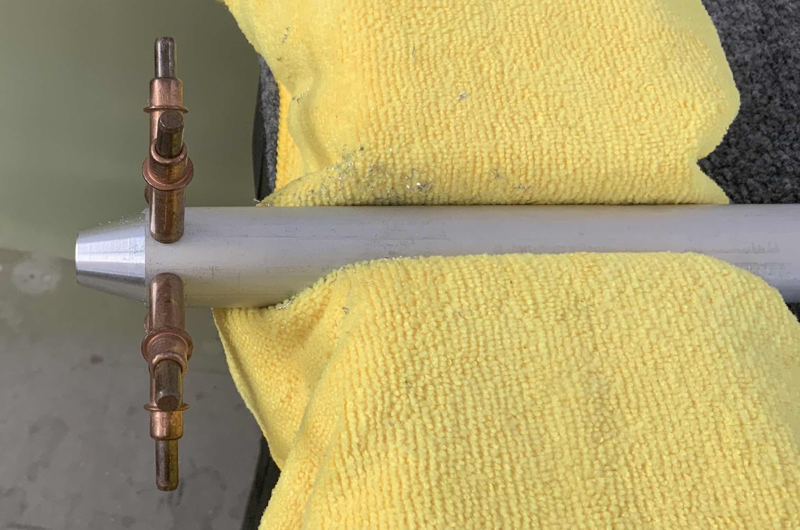
Next, the Threaded Rod End was then inserted into the Pushrod.  “Proper alignment of the Threaded Rod End in the Torque Tube to Bellcrank Pushrod is when the end of the Tube coincides with the edge of the taper in the Threaded Rod End”.  (If you look at the picture above, you can almost see a “line” where the taper starts).  Once the proper alignment was achieved, the Threaded Rod Ends were match-drilled #30 using the #40 pilot holes and a cleco was installed in each hole as it was match-drilled.  In the picture below, all six holes are show match-drilled with clecos installed.

Here is another angle.  You can kinda see the tapered portion of the Threaded Rod End from this angle.

This process was completed for all four ends of the Pushrods.  Prior to disassembly, each end of the Pushrods and the corresponding Threaded Rod Ends were numbers and one hole was marked on each to assure the same parts went back together in the same orientation.


Tuesday, March 26, 2019

Fuselage, FWD/MID Bulkheads (Part 1)


*****Work during this session was completed on Thursday, March 21, 2019*****

I still have some work to complete on the Left and Right Ailerons, but decided to make a change of pace and start on Section 25-FWD MID FUSE Bulkheads.  I’ll go back to the Ailerons after this section, but needed a break from them!  Anyone who has ever built an RV, will know what I’m talking about.

Anyway, this section starts with separating the F-01405B Bulkhead Bars.   Here is what they plans excerpt look like.....

.....and there is what the final product looks like.  I used my Milwaukee Rotary Tool to separate the four Bulkhead Bars.  Next, I used the 6” Scotchbrite Wheel to remove the excess material and make the edges as smooth as possible.  Lastly, I used 220 grit sand paper to complete edge work.

Moving on.....the next step was to dimple the #30 and #40 holes in the F-01405D-L & -R Bulkhead Side Channel flanges (with a few exceptions).  Pictured below are the two pieces with the appropriate holes dimpled.  Kind of hard to see the dimples in this picture, but they are there.  I also completed the edge work after all the holes were dimpled.

Lastly, for today’s session, the #40 holes were dimpled in the bottom flange of the F-01405A Bulkhead Bottom Channel.  Here is the Bottom Channel after all the holes were dimpled.  I also completed all the edge work after the holes were dimpled.

That’s it for the first session on the 3rd Kit (Fuselage).   I’ll pick it up from here tomorrow.

Monday, March 25, 2019

Kit Inventory (Fuselage)

*****I usually update my blog with my iPad using BlogTouch Pro.  After a recent app update, I have been unable to login to the***** app.  So, in order to keep from getting any further behind with new posts, I'm going to update the blog via the website unit it's fixed.

Saturday, March 16, 2019

Today, I started/completed the inventory on the fuselage kit.  Here is what it looks like with the top of the crate removed......tightly packed with all the parts and pieces.  The kit was only missing one Frame Side, a couple of bolts (one was actually bent), and a few nutplates.  There was, however, six parts that were on backorder.  

About halfway through the inventory.....

....and inventory complete (at least they stuff in the shipping crate).


Now on to the hardware.....this damn bag of hardware had to of weighed 15 pounds!

All of the parts are now put away and waiting.....


Sunday, March 24, 2019

Kit Delivery (Fuselage)

*****I usually update the my blog with my iPad using BlogTouch Pro.  After a recent app update, I have been unable to login to the***** app.  So, in order to keep from getting any further behind with new posts, I’m going to update the blog via the website until it’s fixed.

Friday, March 15, 2019

Today, my fuselage kit was delivered by Saia LTL Freight.  This was my first experience with this freight company and I was very happy with their service.

There was no visible damage to the shipping crate itself; however, some of the staples were pulled away from the top of the crate as shown below.  The banding straps held the top on with no problem.  


Monday, March 4, 2019

Wings, Ailerons (Part 19)

Yesterday, I treated the Nose Skin, Spar, and Outboard/Inboard Hinge Brackets with Alumiprep and Alodine.  Today, I primed them with Akzo.  The Nose Skin and Spar are shown below after being primed.  The Inboard and Outboard Hinge Brackets will be discussed along with the second picture below.


In Part 16, I discussed how I messed up the Inboard/Outboard Hinge Brackets by countersinking them on the wrong side.  As I mentioned, I ordered the new Brackets from Van’s and completed the prep work on them by priming them today.  In the picture below, I have identified the newly completed Inboard and Outboard Hinge Brackets after being riveted to the their respective Main Ribs.  Additionally, you can see the Doubler that was riveted to the Spar.

Sunday, March 3, 2019

Wings, Ailerons (Part 18)

Today’s session was spent preparing the Spar, Nose Skin, and Inboard/Outboard Brackets (the one’s I re-ordered from Van’s last week) for the Right Aileron.  I decided to start on the Spar by deburring all the #30 holes (webs) and #40 holes (flanges) and then dimpling the #40 holes in the flanges with my pneumatic squeezer.

The next order of business was to cleaned the Spar edges.  My buddy got a new tool from Aircraft Tool Supply Company (ATS), so I decided to try it out.  The tool is a Detail Sander/Polisher and uses these 1-1/4” Sanding Disc (220 grit) and 1-1/4 Sanding Disc (180 grit) to sand your material.  I was very impressed with the results.....this little dude saved a lot of time.  I wasn’t able to use the tool with the lightening holes, so those had to be handsanded like I always do.

Once the Spar was completed, I moved on to the Nose Skin.  I deburred all the holes (all were #40) and dimpled them with my pneumatic squeezers.  I did not used the tool I mentioned above on the Nose Skin edges because it was so thin and I didn’t want to slip and mess it up.  So, I just hand sanded the edges.


Saturday, March 2, 2019

Wings, Ailerons (Part 17)

In Part 9, I identified a mistake I made while installing the Counterbalance for the Right Aileron.  As a result, and to easy my mind, I ordered and received the replacement parts from Van’s.  The three picures below show the “new” completed install of the Counterbalance on the Right Aileron.

The picture shows the Nose Skin with all the clecoes in place after preparation....including the 10 #30 clecos in the leading edge.

The two pictures below show a couple angles of the counterbalance install.  The second time around, it came out perfect and just like the Left Aileron.  Very happy with this work.....

Friday, March 1, 2019

Wings, Ailerons (Part 16)

I started today’s session by prepping the Nose Skin for the Left Aileron.  I cleaned the edges, deburred the holes, and dimpled the holes with my pneumatic squeezer.  Once the Nose Skin was completed, the entire Left Aileron was clecoed together for.....

Step 1:  Lay the assembly flat on the table top hanging the clecoes which are holding the A-1001A-1L Nose Skin to the A-1002-1 Bottom Skin and A-1003-1L Spar over the edge.  Use a straight board to distribute weight over the main ribs to keep the skin firmly against the table with no twist.”

Step 2:  Check the A-1001A-1 Nose Skin for bowing with a straight edge held spanwise midway between the leading edge and spar.  About 1/16 [1.6 mm] of rise is acceptable.  If necessary, squeeze the skin down by hand to minimize the bow.”

In the picture below, I have complied with the instructions of Step #1.  The Aileron is hanging off the edge of table as described above with my 6’ backriveting plates laying across the Main Ribs.

I complied with Step #2 as shown in the picture below.  I used a three foot steel ruler as described above to check for bowing.  The ruler was almost completed flush across the whole span of the Aileron.  So, I’m going to call this step complete.

Previously, I discovered that I countersunk the Inboard and Outboard Hinge Brackets for the Right Aileron on the wrong side.  Because of this mistake, the Inboard and Outboard Hinge Brackets for the Left and Right Ailerons were dimpled on the same side....and should have been mirrors of each other.  As a result, I had to place a parts order with Van’s.  The parts arrived today, so I verified SEVERAL times I had the correct side (this time) and countersunk the Brackets as directed in the plans.  Here are the “new” Brackets.


Wednesday, February 27, 2019

Wings, Ailerons (Part 15)

I worked on preparing the Spar and Nose Skin tonight for the Left Aileron.

The Spar:  deburred all the holes, dimpled all the #40 holes in the flanges, and cleaned all the edges with 220 grit sandpaper

The Nose Skin:  Deburred all the holes and cleaned the edges with 220 grit sandpaper.


Tomorrow, I will dimple the Nose Skin and then both pieces will be ready to be treated with Alumiprep, Alodine, and Akzo Primer.


Tuesday, February 26, 2019

Wings, Ailerons (Part 14)

I spent tonight’s session backriveting the last four Main Ribs and 24 Stiffeners to the three remaining Skins.  I used a 3.5” Back Rivet Set and 12” Back Rivet Set to set all the rivets.  Just like in yesterday’s session, the plans called for AN426AD3-3 rivets, but I felt they were a little short.  According to my guage, the AN426AD3-3.5 were a perfect length.....so, I used them again tonight.  

I could use the 3.5 Set on all the rivets for the Stiffeners, but the 12” Set had to be used for a couple of the rivets on the Main Ribs.


The results look similar to Part 13, so not any pictures for tonight.  However, here is a sweet video.....wish I could work this fast for real!!!

Monday, February 25, 2019

Wings, Ailerons (Part 13)

During the previous session, I treated the 32 Stiffeners and four Skins with Alumiprep and Alodine.  To start today’s session, I Akzo Primed the same pieces.  Here are all the pieces after getting primed.

After the Akzo Primer has dried, I started backriveting the Stiffeners to the Skins.  Below, is one of the two Bottom Skins with the rivets installed and held into place with the orange tape.

Kind of hard to see here, but this is the opposite side of the picture above.  If you look closely, you can see rivets installed in the holes prior to being set.  The plans call for AN426AD3-3 rivets to be used to attach the Stiffeners, but they looked short to me.  After checking them with he gauge, they were a little short and the AN426AD3-3.5 measured out perfectly.....so, I used them here.  

Here are the manufactured heads after being set.....

.....and the shop heads with the Stiffeners in place.

Here is a close up of the eight rivets attaching the A-1005B-1L Main Rib to the Bottom Skin.

Here is an example of one of the eight Stiffeners attached to the Bottom Skin.

I was able to complete the riveting of the eight Stiffeners and two Main Ribs for the Left Aileron Bottom Skin.  I will pick it up here during the next session and complete the remaining three Skins.

Sunday, February 24, 2019

Wings, Ailerons (Part 12)

Fairly short, but necessary session today.  I treated the 32 Stiffeners, two Top Skins, and two Bottom Skins with Alumiprep and Alodine.  I’ll let them hang up overnight to dry and Akzo prime them during the next session.

Here are the four Skins.....


.....and the 32 Stiffeners.

Saturday, February 23, 2019

Wings, Ailerons (Part 11)

No exciting work during this session.  I cleaned the edges of the Top and Bottom Skins of the Left and Right Ailerons (Skins shown in the previous post that were dimpled).

Wings, Ailerons (Part 10)

The work during this session was completed on Friday, February 22, 2019.

Pretty straight forward night at the shop.....I deburred and dimpled the holes in the Top and Bottom Skins for both the Left and Right Ailerons.

Thursday, February 21, 2019

Wings, Ailerons (Part 9)

In Part 6, I prepared the Counterbalance for the Left Aileron.  During today’s session, I completed the same steps for the Counterbalance on the Right Aileron.  Here are the completed leading edges for the Left and Right Ailerons. 

After I completed the work on the right Counterbalance today, I wasn’t completely happy with it.  The plans want the Counterbalance to be flush with the outboard edge of the Nose Skin.  The picture below shows the Left Aileron (completed in Part 6).  You can see the Counterbalance is perfectly flush with the Nose Skin in the area circled.


Here is the Right Aileron.....not really happy with the result.   In the circled area of the picture below, you can see that the Counterbalance is NOT exactly flush with the Nose Skin.  How did this happen?  


When I originally fit the Counterbalance to the Nose Skin, two #40 holes were match-drilled on either end of the Counterbalance with the Nose Skin.  Eventually, the Counterbalance was removed from the Nose Skin for addition preparation steps.  Then, the Counterbalance was reinstalled to make the remaining eight #40 match-drilled holes in the leading edge of the Nose Skin.  My guess is I swapped ends on the Counterbalance when I reinstalled it for this step.  So, the end of the Counterbalance you see in the picture above, should have been on the other end (or the outboard end).

I haven’t called Van’s regarding this mistake and I’m sure I could leave it this way and it wouldn’t cause any problems.  However, it’s not right.  I’ve said it before and I’ll say it again....I’m not going to build a PERFECT airplane, but I can get it as close to RIGHT as possible.  So, following that philosophy, I ordered a new Counterbalance and Nose Skin from Van’s.