Wednesday, January 24, 2024

Panel Build (Part 4)

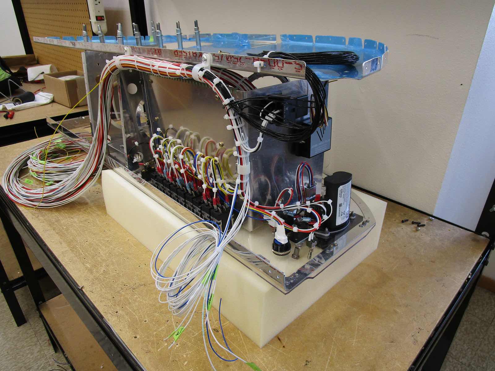
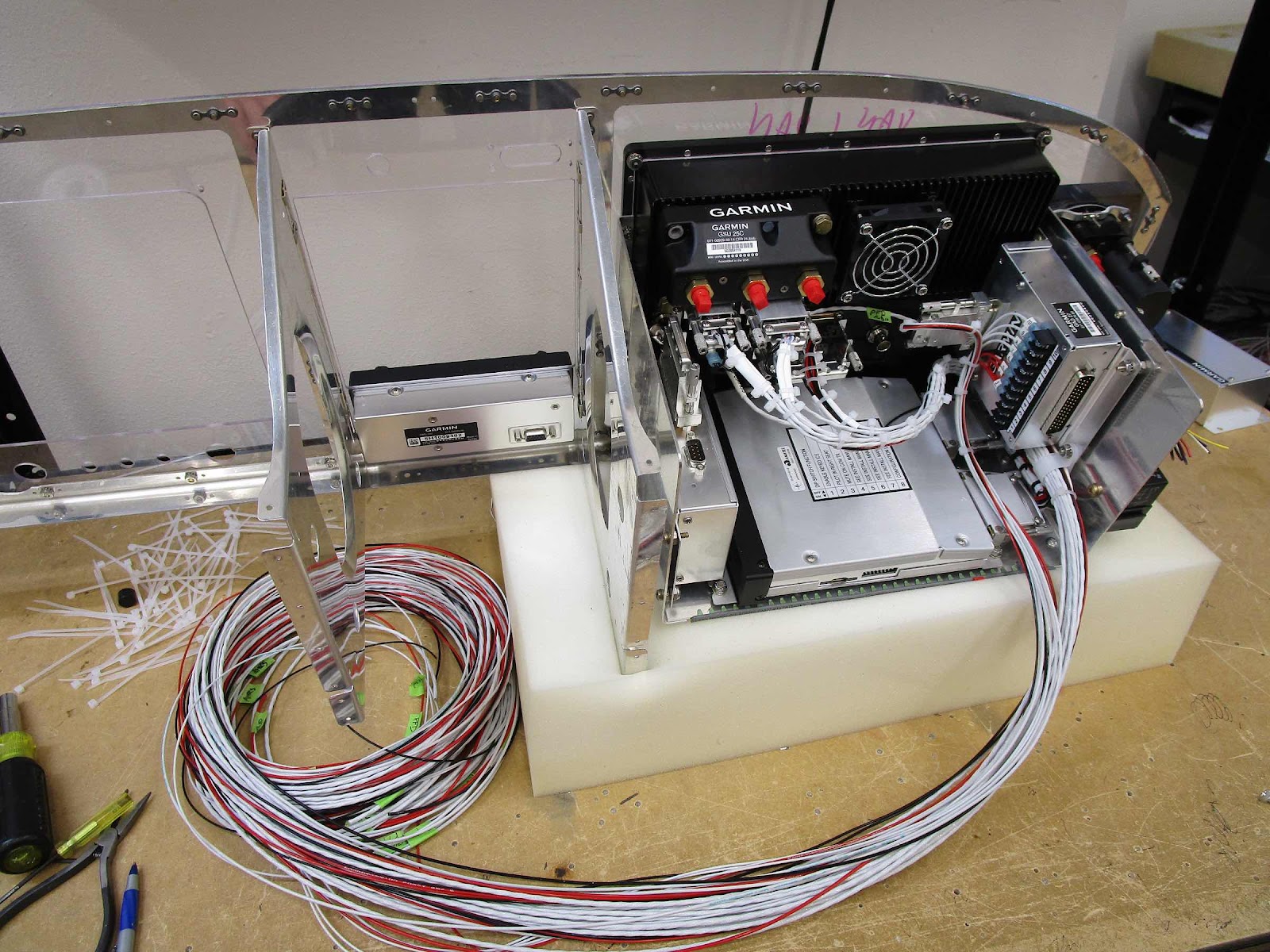
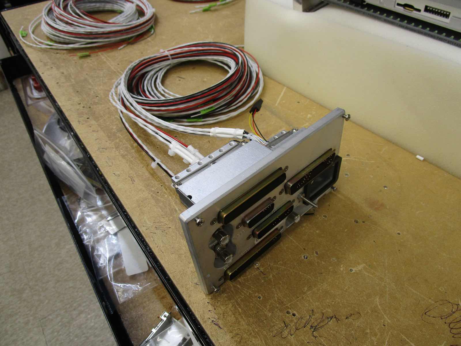
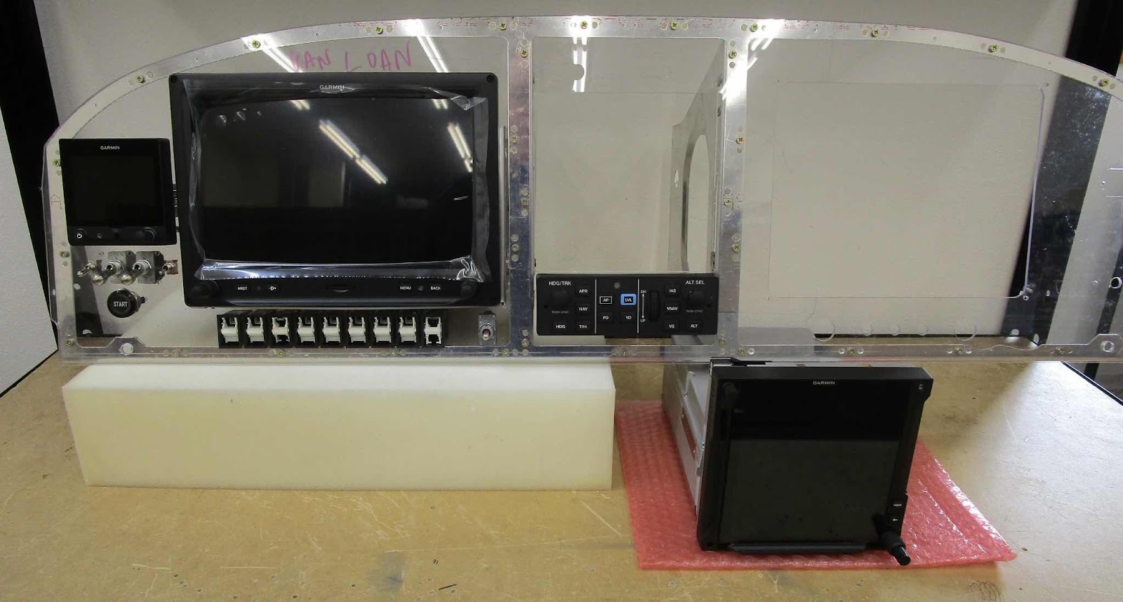
The four pictures attached to this post are from February 22, 2022.  Lots of wires…..lots of them.  The panel is starting to come together.  Jason said almost everything on the panel is wired.  He will have that completed in the next couple of days and move on to the mating connectors for everything that will be off the panel.


*****Picures from Jason at Aerotronics*****

Panel Build (Part 3)

This picture is from February 2, 2022 and show the ADAHRS and Audio Panel fully wired, the PFD and GAD 27 partially wired and the various wire runs.

*****Pictures from Jason at Aerotronics*****

Panel Build (Part 2)

The two pictures are from January 20, 2022.  This shows most of the wiring for the GTN750Xi.


*****Pictures from Jason at Aerotronics*****

Monday, January 22, 2024

Panel Build (Part 1)

Now that the panel design has been finished/approved in Part #7, its build was assigned to Jason Springstead at Aerotronics.

First of all, I must lead this post by saying Jason was awesome to work with during the process.  To say that his customer service was good is an understatement!  He responded to all my questions (which he has probably heard the same questions a million times), on the phone and via email, within a day (usually within hours).  He was always honest with the answers to my questions and gave great advice on things that worked well together and things that did not (in terms of avionics).  During the build, if he had a question for me regarding the panel, he contacted me to see what I wanted…..instead of just guessing.  

I also asked him to occasionally send me some pictures of the panel build to post in this blog (finally getting around to doing that).  Jason sent me all of the panel pictures that you will see in the next several posts that will be published.

*****These pictures are from January 12, 2022*****

Jason said he tries to get as many items on the mounting tray as he can (second picture below)…..which leaves less items for me to have to mount somewhere off panel.  This is the front view of the panel with most of the items mounted in the panel templete:

G3X Touch 10.6” GDU 460 Display Unit
G5 EFIS
GMC 507 A/P Control Panel
GTN 750Xi GPS/Nav/Com/Map (I will have to install it when the panel is delivered)

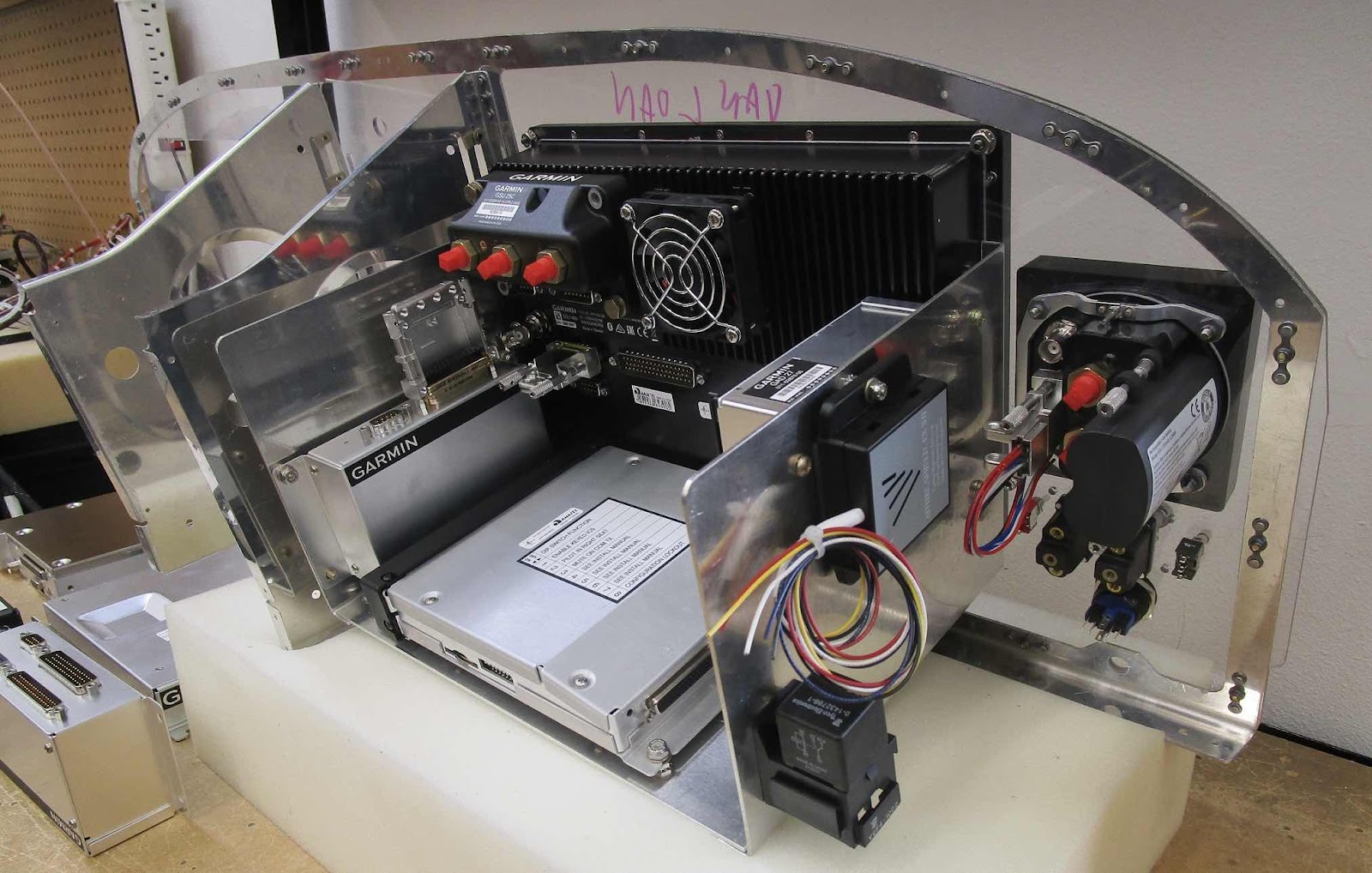
This is the backside of the panel showing the “mounting tray” he uses for a majority of the equipment.  In this picture, you can see the:

GAD 27 Integrated Controller
GMA 245R Remote Audio Panel
GSU 25C ADAHRS
GAD 29 ARINC 429 Interface
Aithre Shield 3.0 CO Detector

Lastly, shown below are the items I will have mount off panel somewhere when I receive the finished product:

GEA 24 EIS Interface Module
GTR 20 Remote Comm
GTX 45 Remote Transponder ADS-B In & Out
TCW Intergrated Back-up Battery System 6 amp-hour

More to follow…..

Sunday, February 19, 2023

Exhaust System (Part 4)

The following work was completed on Saturday, February 4, 2023.

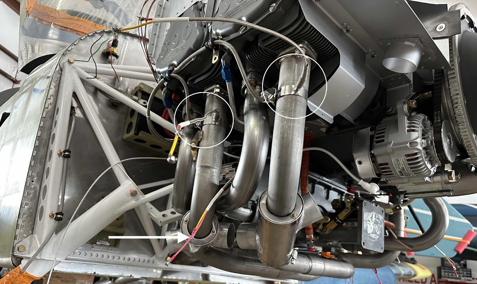
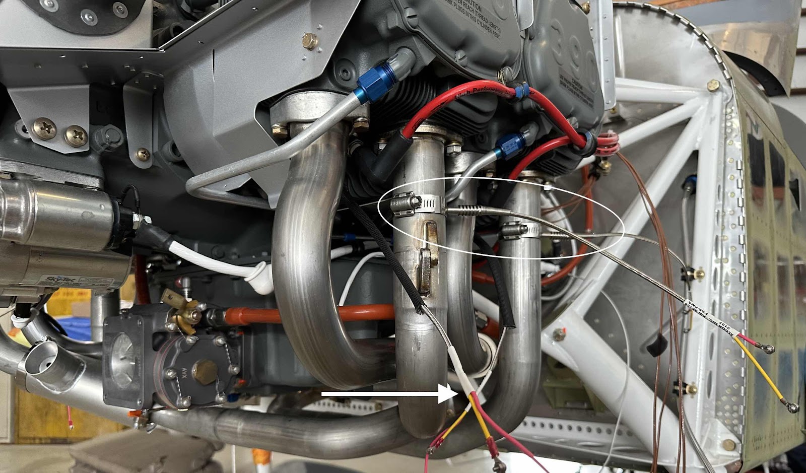
Now that the exhaust has been installed, I started installing the Exhaust Gas Temperature (EGT) and Cylinder Heat Temperature (CHT) probes.  In the “Avionics and Panel” section of the blog, I talked about my decision to use Garmin Avionics and to have our panel built by Aerotronics.  When Aerotronics shipped me the panel, the EGT and CHT probes were supplied with the panel.  The probes they supplied were from the Thermocouple and Probe company Alcor.  This link specifically discusses the EGT probes and this link discusses the CHT probes.

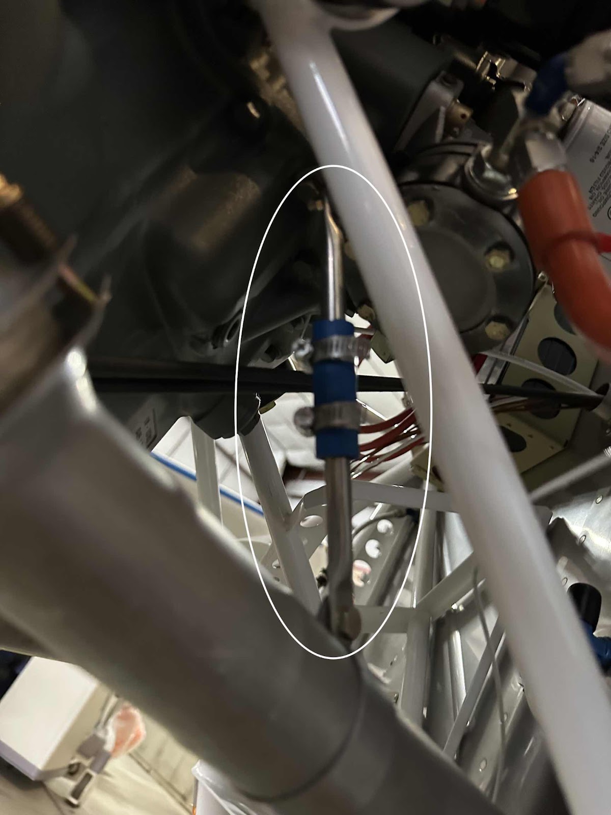
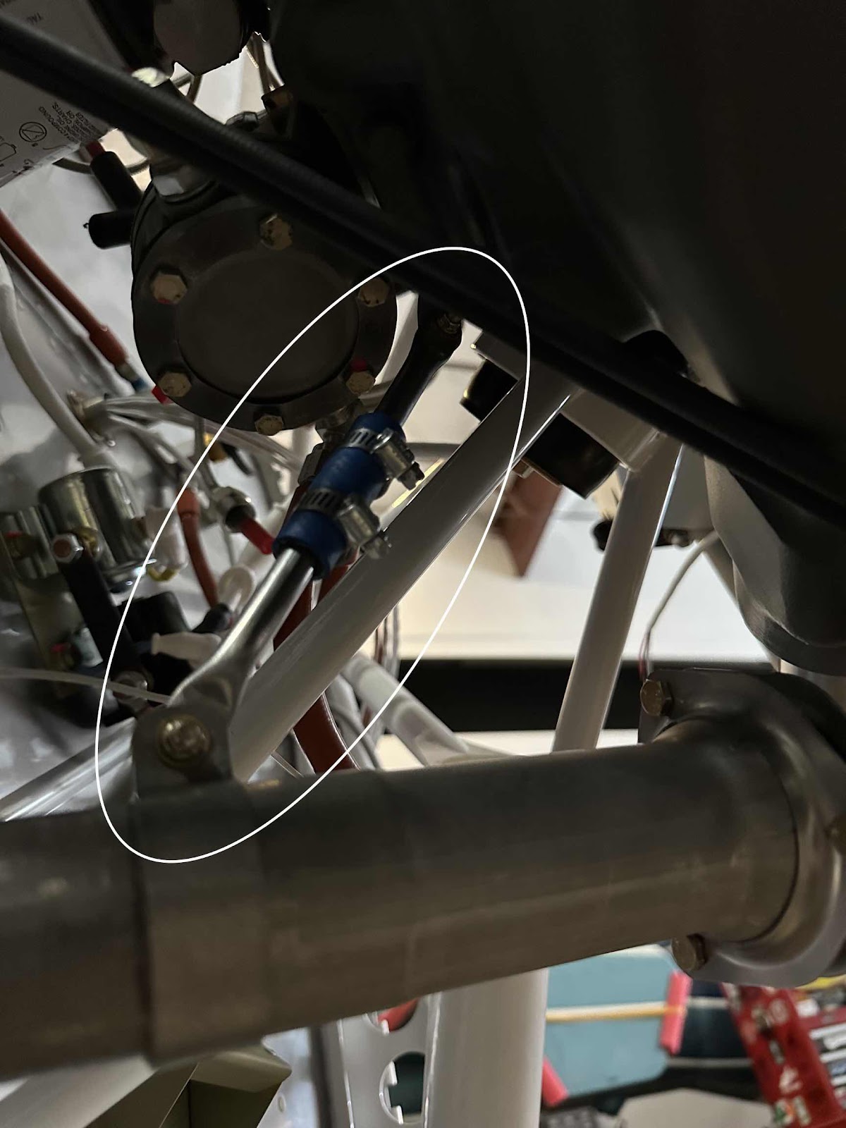
I followed the instructions provided with the probes (same as directed to in the links) and installed the EGT and CHT probes.  In the two pictures below, I circled the four EGT probes and used arrows to point to three of the four CHT probes.


During the next work session on the Exhaust System, I will connect the EGT and CHT probe leads to their correct instruction leads from the Garmin GEA24 (Engine Indication System).  This step will also require wire runs to be figured out, connections covered with heat shrink and wire runs secured properly with adel clamps where necessary.  Still a fair amount of work to compete the probes install.

Wednesday, February 15, 2023

Exhaust System (Part 3)

The following work was completed on Friday, February 3, 2023.  

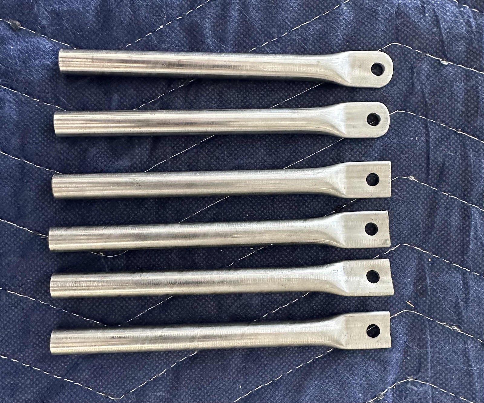
I started this work session by making the Forward Exhaust Hanger Brackets.  The first step was to modify two of the Exhaust Support Tubes.  Each tube had to be be cut to a length of 3 1/4 inches, have the corners of the bolt end rounded and the opposite end flared.  This picture only shows the rounded bolt ends of the two tubes.  Next, I used a band saw to cut the tubes to the appropriate length and flared the opposite end. (More on that below).

 One of the tubes is bolted to the Oil Sump and the other tube is bolted to an Exhaust Hanger Bracket.  The tubes are then joined together by using a length of rubber hose secured by two stainless steel hose clamps.  As mentioned earlier, the idea behind flaring the opposite end of the support tube is to create a lip preventing the rubber hose and hose clamp from sliding off the tubes.  

**Regarding the flared end of the tube:  the instructions say to use a vice to compress the end of the tube (to values shown in the plans), thus making the lip.  I’m sure the process works fine, but I didn’t really like it.  So, since all that is needed is a lip, I used a tube flaring tool to create a perfectly round lip all the way around the tube.  (Be careful not to make the flare to large or it will be difficult to insert it into the hose).  I liked the outcome this process produced on the tube.  The pictures below show a couple views of the completed and installed Forward Exhaust Hanger Assembly.


Next, I installed the Heat Muff Assemblies.  The assemblies are installed by first connecting the two stainless steel rods to the four Heat Muff Ends (two separate pieces make up each end).  The plans specify the length from the outside edges of the Ends should be approximately 7 3/8”.  The assembly is held in place by friction resulting from bending the inner “teeth” of Heat Muff Ends inward to create a tighter clamping force when the rods are installed.  This is the forward assembly….the rear assembly is installed in the same manner.

The Heat Muff Skin is now installed around the assembly and secured with stainless steel clamps around the Heat Muff Ends.  This is also the Forward Heat Muff.

This picture shows the forward and aft Heat Muffs completely installed.  There are six sections of Scat Hoses that now need to be installed.  I will wait until I finish running all the control cables, wires, etc before I install them to allow space to work.

Exhaust System (Part 2)

I was able to install most of the exhaust system from February 2 - 5, 2023.  This post is from the first session on Thursday, February 2nd.

Previously, I had explored other options for the exhaust system due to the backordered status of the Van’s supplied exhaust (at one point I was told 6-8 months).  Lucky for me, that time frame was greatly reduce and I received the Van’s supplied exhaust in a couple of months.  I had always wanted to use the Van’s supplied exhaust in the first place…..it was “designed” around the IO-390, Van’s used it on their prototype, it fit in the cowling, the install should be easier, etc.

I can say, the install of the exhaust system up to this point, has been very straight forward and has required NO modifications to anything.  It went together according to the plans and bolted to the engine perfectly…..couldn’t have been any easier!  (I know, famous last words)

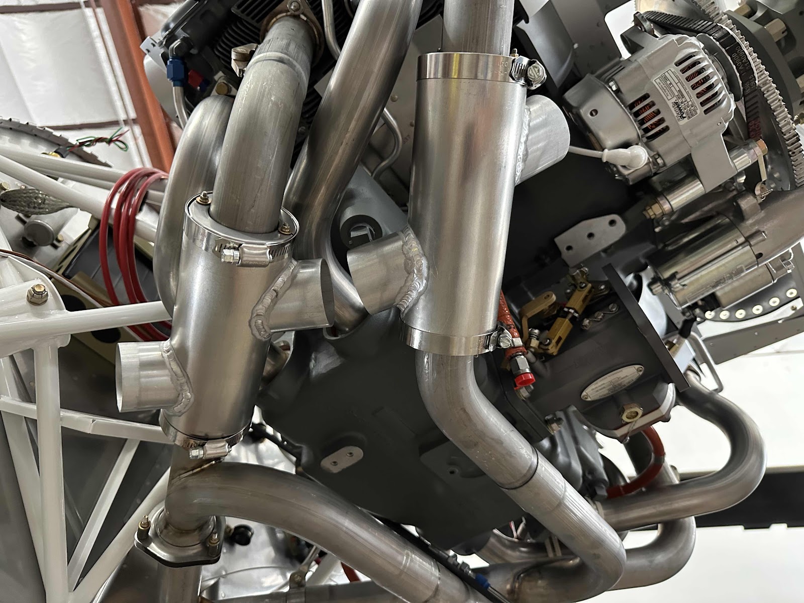
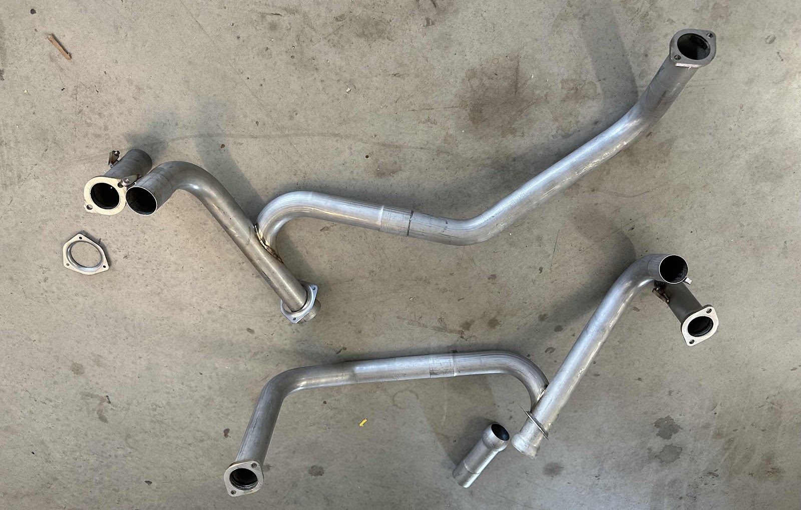
Here is the exhaust (minus the heat shrouds) “connected” and ready to be lifted to the engine.  It did, however, take me SEVERAL minutes of spinning and flipping the plans around and holding up exhaust sections to make the picture in the plans make sense.  But, I eventually figured it out.


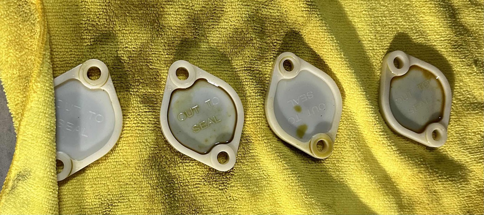
To begin the install, I had to remove the four blanks installed by Lycoming when they shipped me the engine.  (One for each cylinder).


When I ordered the engine from Lycoming, they sent it to me with preservative oil in it (which I requested) for long term storage…..the sticker on the side of box translated that to six months under “ideal conditions”.  When I took the blanks off the cylinders, about an ounce or so of the preservative oil also came out.

Here is where the blanks were installed for cylinders #1 & #3 (on the right side)…..

…..and cylinders #2 & #4 (on the left side).

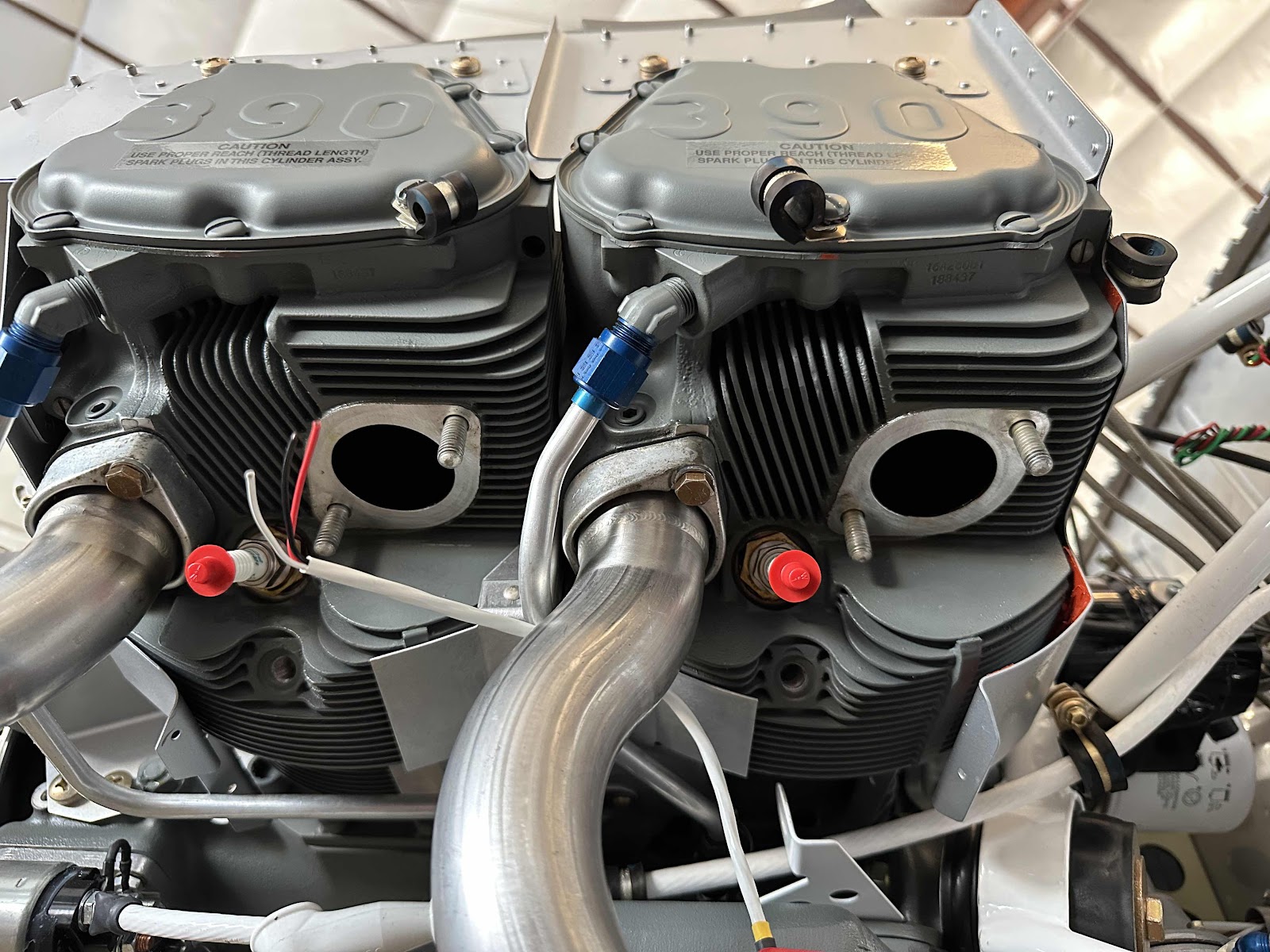
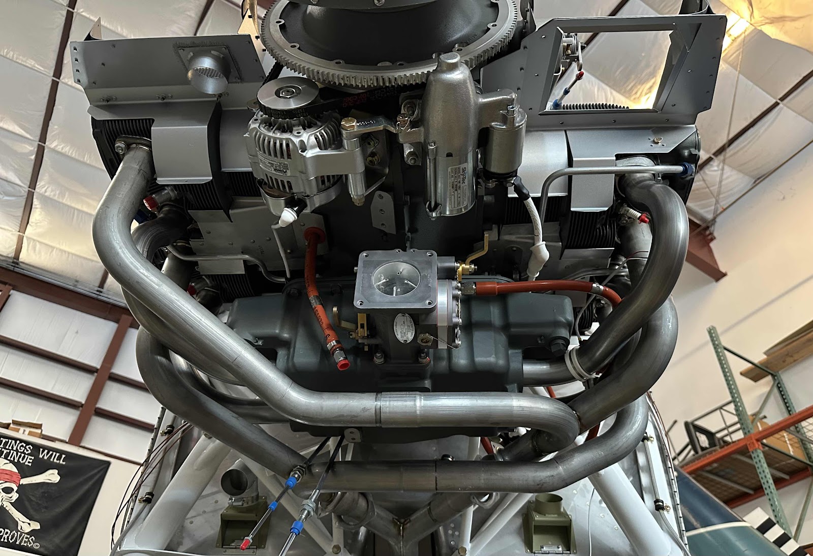
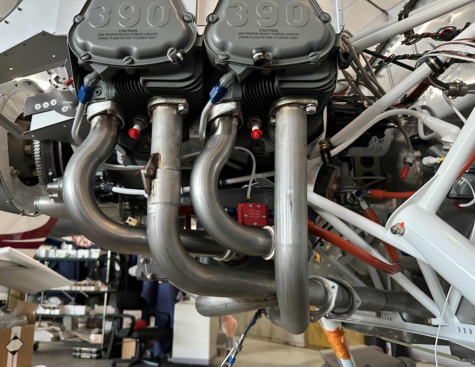
Here is three angles showing the exhaust initially installed in place on the engine.


Wednesday, January 12, 2022

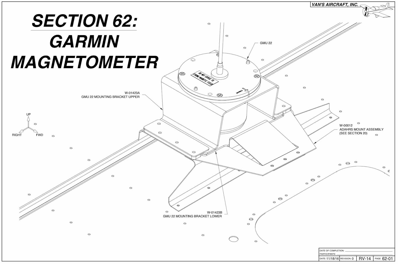
Garmin Magnetometer (Part 1)


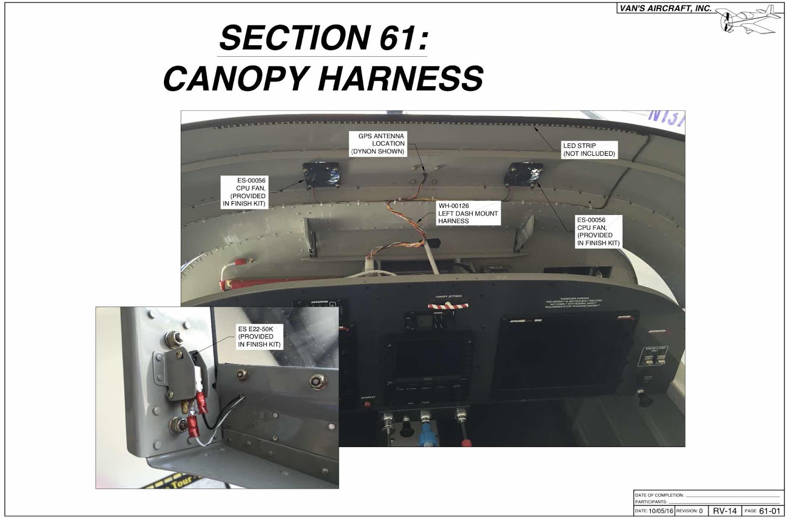
Canopy Harness (Part 1)


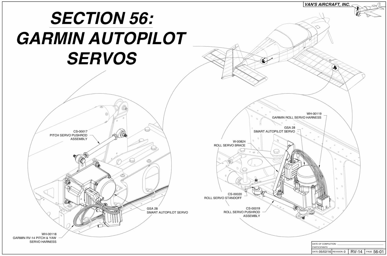
Garmin Autopilot Servos (Part 1)


Common Fuselage Harness (Part 1)


Flap Position Sensor (Part 1)


The ES MSTS POS-12 Flap Position Sensor from The Ray Allen Company is the position sensor used for flap position input to EFIS displays on the RV-14.

After doing some research and looking at the plans for this section, I decided I wasn’t the biggest fan of this system.  The installation seemed easy enough and works for many other builders, but I wanted to research other options for the flap motor/position sensor setup.

During my search, and with a recommendation from Aerotronics, I was turned onto the RV Max Flap Actuator from PH Aviation Services, Inc.  

This is ultimately the setup I decided to go with, so I won’t be completing this section of the plans.

Please see the RV Max Flap Actuator installation under the Modifications & Upgrades section on the right.

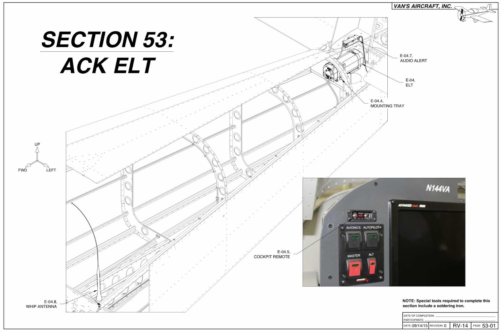
ACK ELT (Part 1)


Firewall Forward Miscellanea (Part 1)


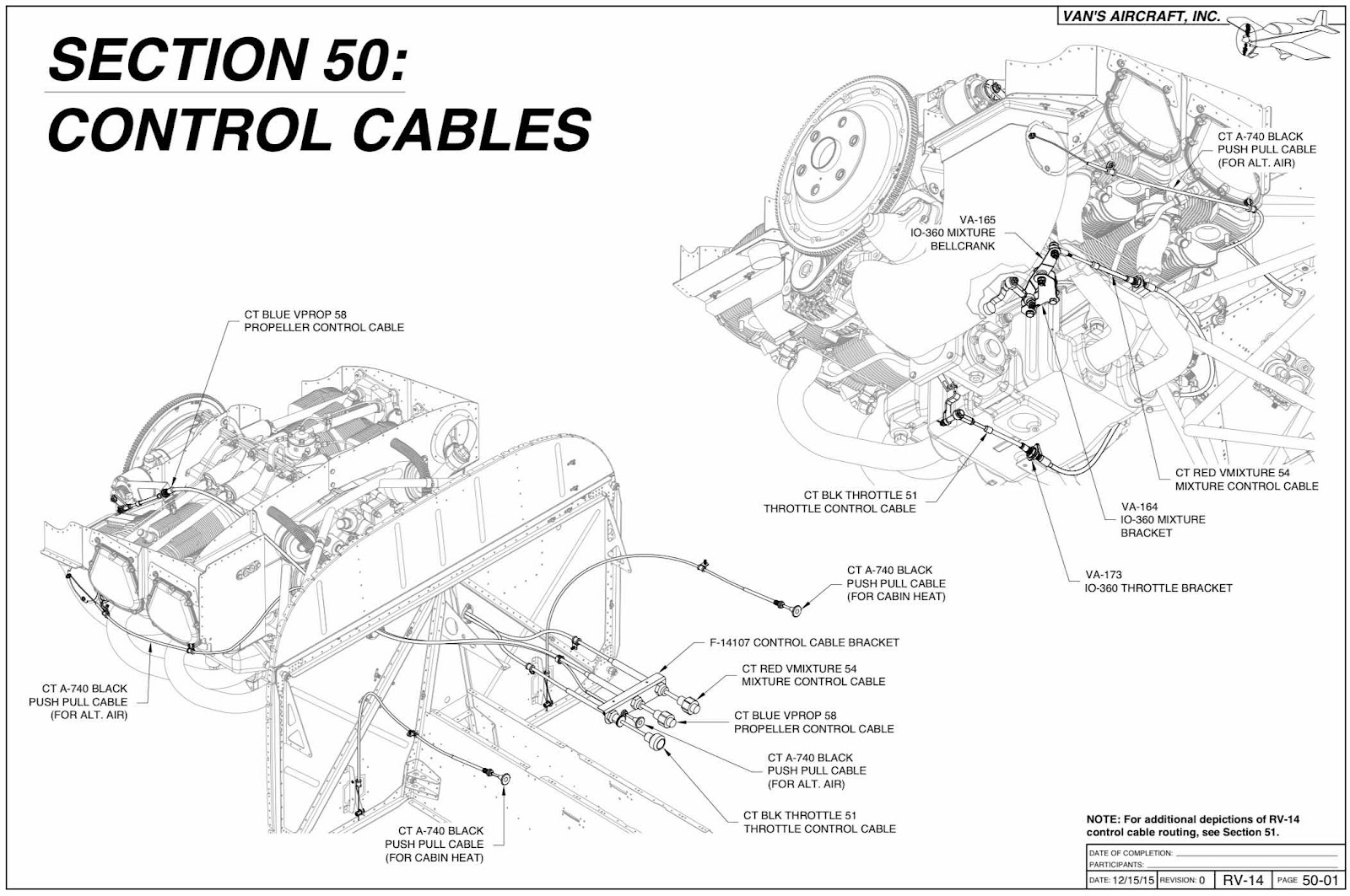
Control Cables (Part 1)


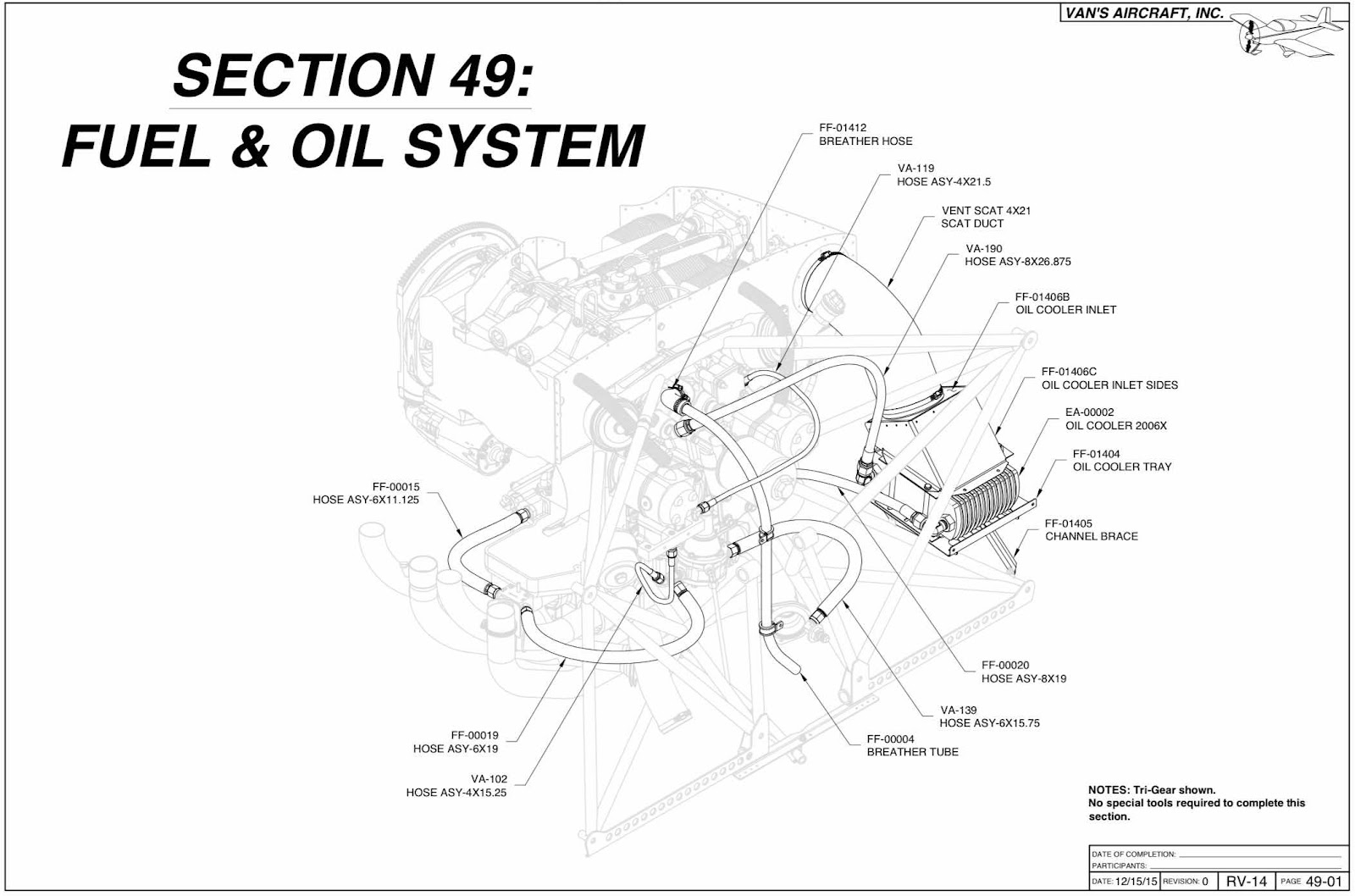
Fuel and Oil System (Part 1)


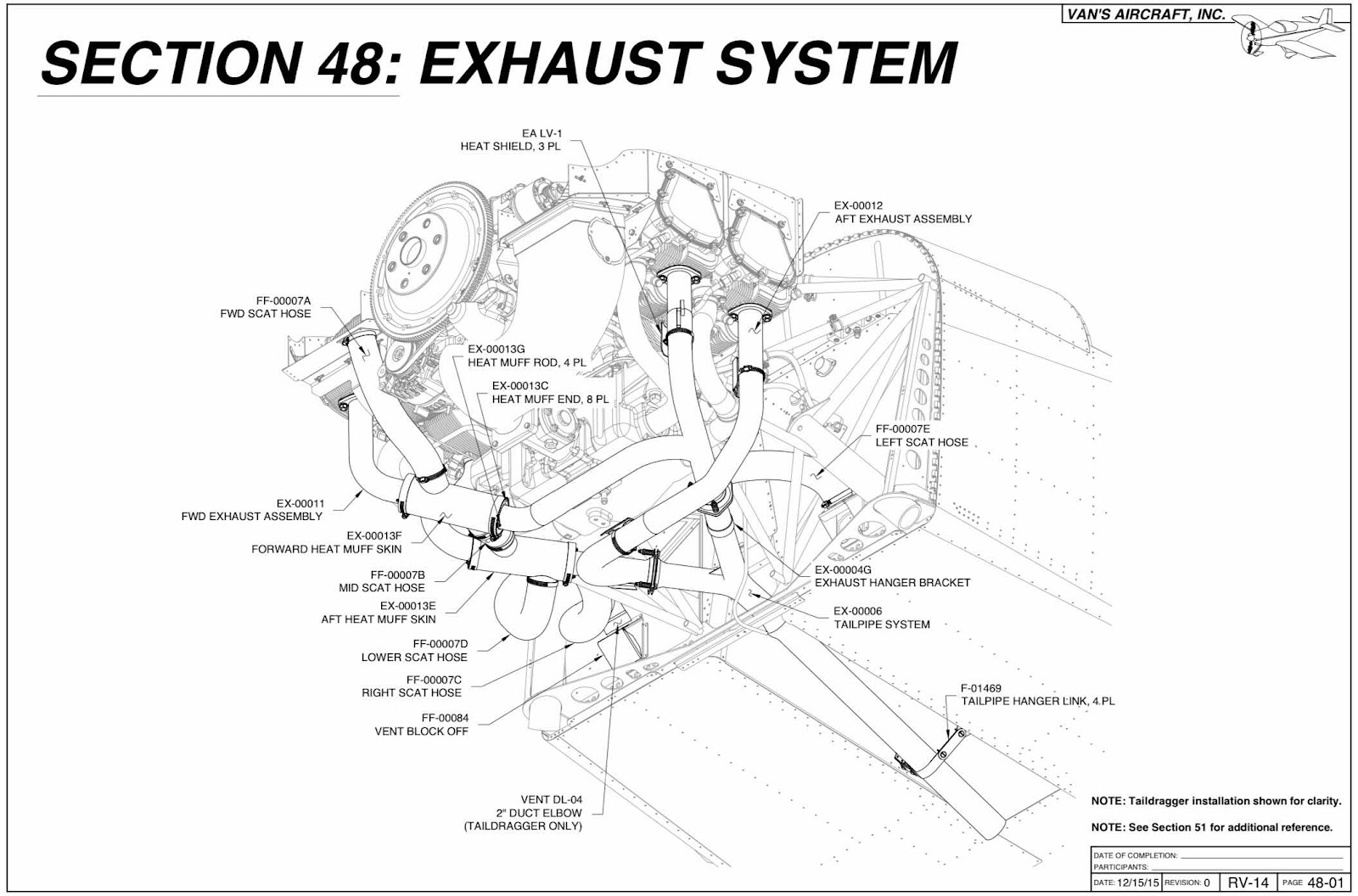
Exhaust System (Part 1)


Engine Installation (Part 1)


Panel Design (Part 7)

Well, we have finished our panel design process with Aerotronics.  The whole process with them has been great!  From initially working with Andre for the panel design….to now working with Jason for the actual panel build.  Both of those guys have been awesome to work with.  When it’s time to build your panel, I would definitely recommend Aerotronics.  I’m kicking around the idea of build an RV-10 after the 14 is complete.  If I do, I will definitely use Aerotronics again for the panel.

So, here is the 7th and final iteration of our panel design…..
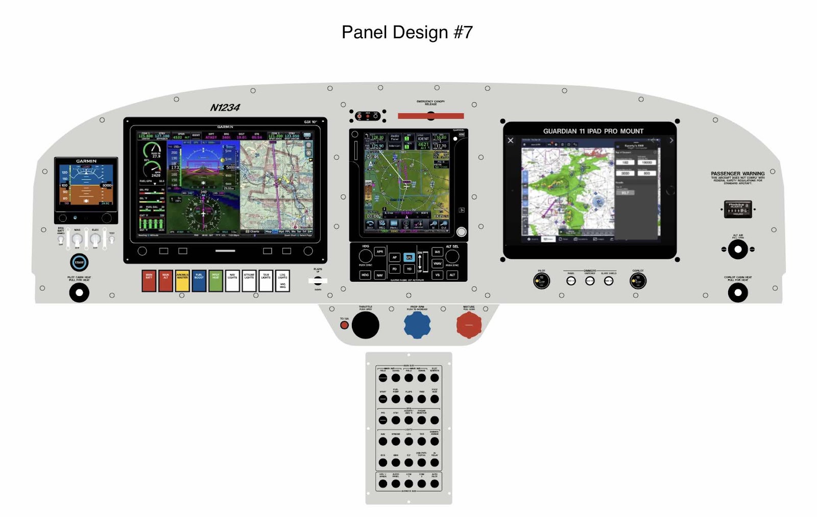
There were only a few changes from the previous #6 design.  We decided to swap the location of the HOBBS meter and Passenger Warning.  My wife is going to design a personalized Passenger Warning and this gives her more room to work with.  We are working on a design and I will post it on the blog when we get it finalized.  It won’t be to elaborate, but we just didn’t want the standard warning and something personalized.
We also decided to incorporate a switch for the “Wig Wag” function into a multi-positional switch for the “wig wag’s” and “landing light”.  I’m still planning on using the airspeed function on the GAD27 to control the wig wag’s via airspeed, but I still wanted a switch option for any reason I decided to operate the wig wag’s outside of the airspeed parameters.

Lastly, we are going to use the third GAD27 dimmer switch (far right) for the glareshield light.

That’s it.  The panel design is complete to our liking and Aerotronics has begun the building it…….

I will update this section as I get pictures/progress updates from Aerotronics.