This blog was created to memorialize the building process of my Van's Aircraft RV-14 and to satisfy the requirements for certification in the Experimental Amateur Built Aircraft category. It will also serve as a central location for ME to reference in the future on processes and techniques I used during the build. Additionally, it will allow my family, friends, and other interested builders the opportunity to follow along during my build…..and might be helpful to someone along the way.
Wednesday, June 10, 2020
Wednesday, June 3, 2020
Saturday, April 25, 2020
Fuselage, FWD/MID Side Structure (Part 41)
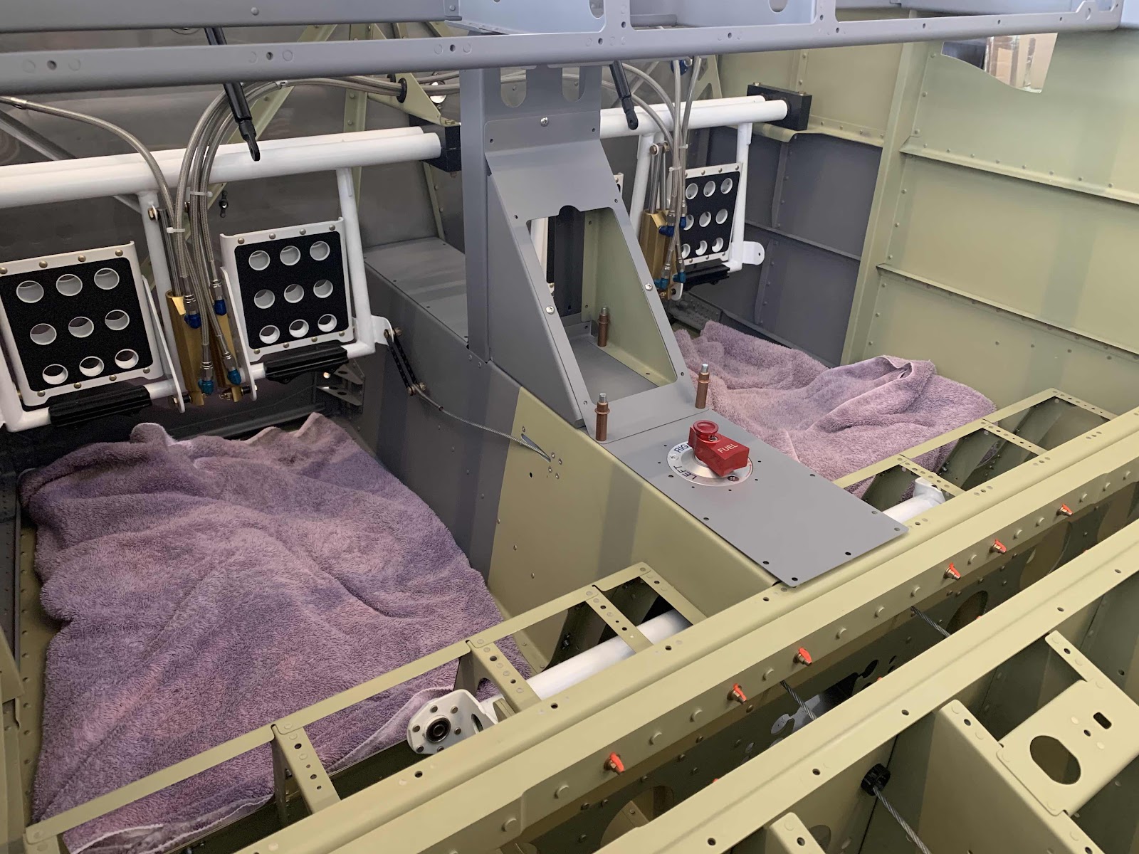
I previously delayed the next few steps from when I was working on Section 29 in early January (reason for the gap in this and the previous Part) for a couple reasons. One: I ordered, and was waiting on, the black aluminum vents from Van’s to replace the plastic ones from the kit. Two: There is a note in the plans that says, “Delay the following steps until after the completion of Section 35 to eliminate the possibility of interference with the bottom of the instrument panel”.
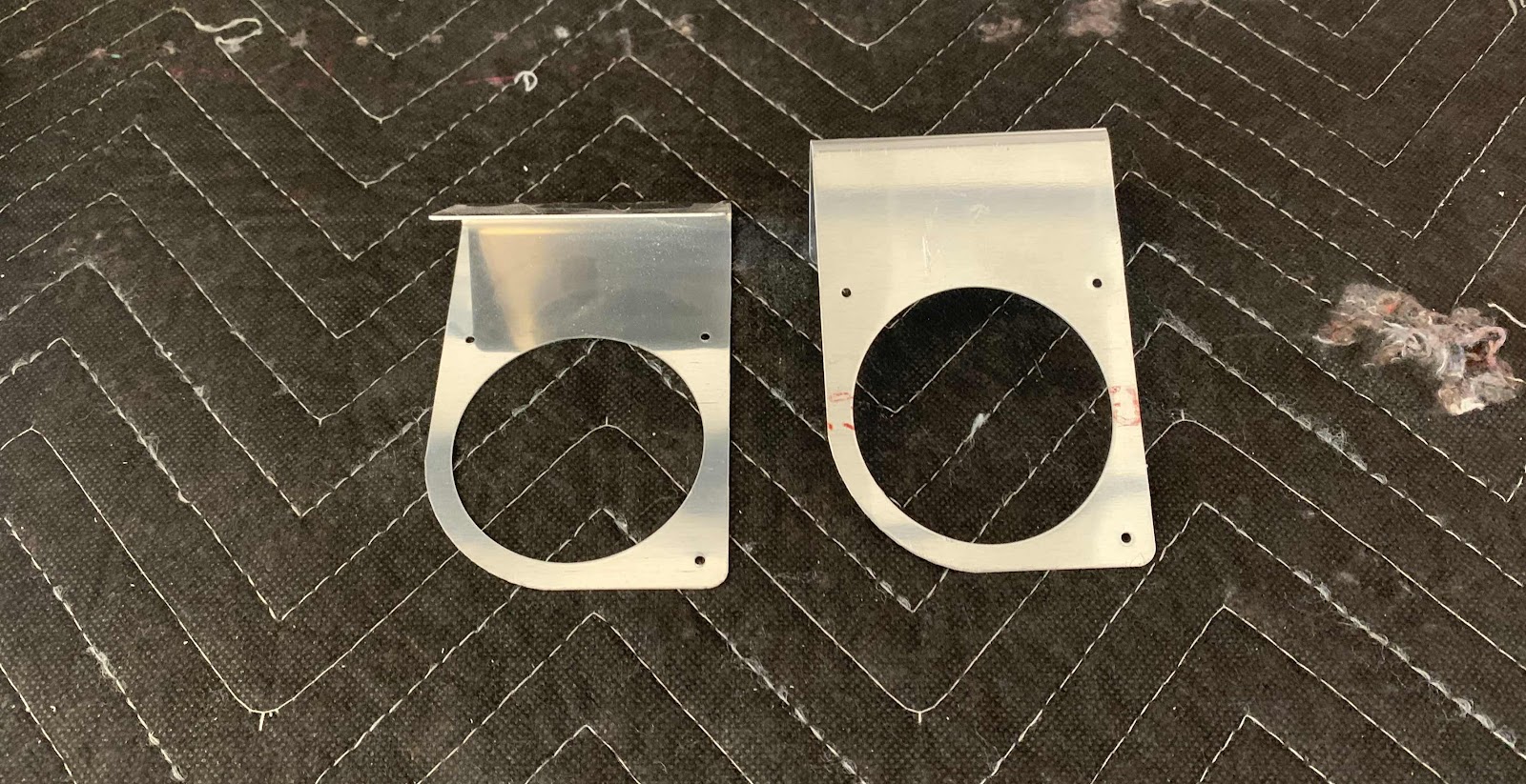
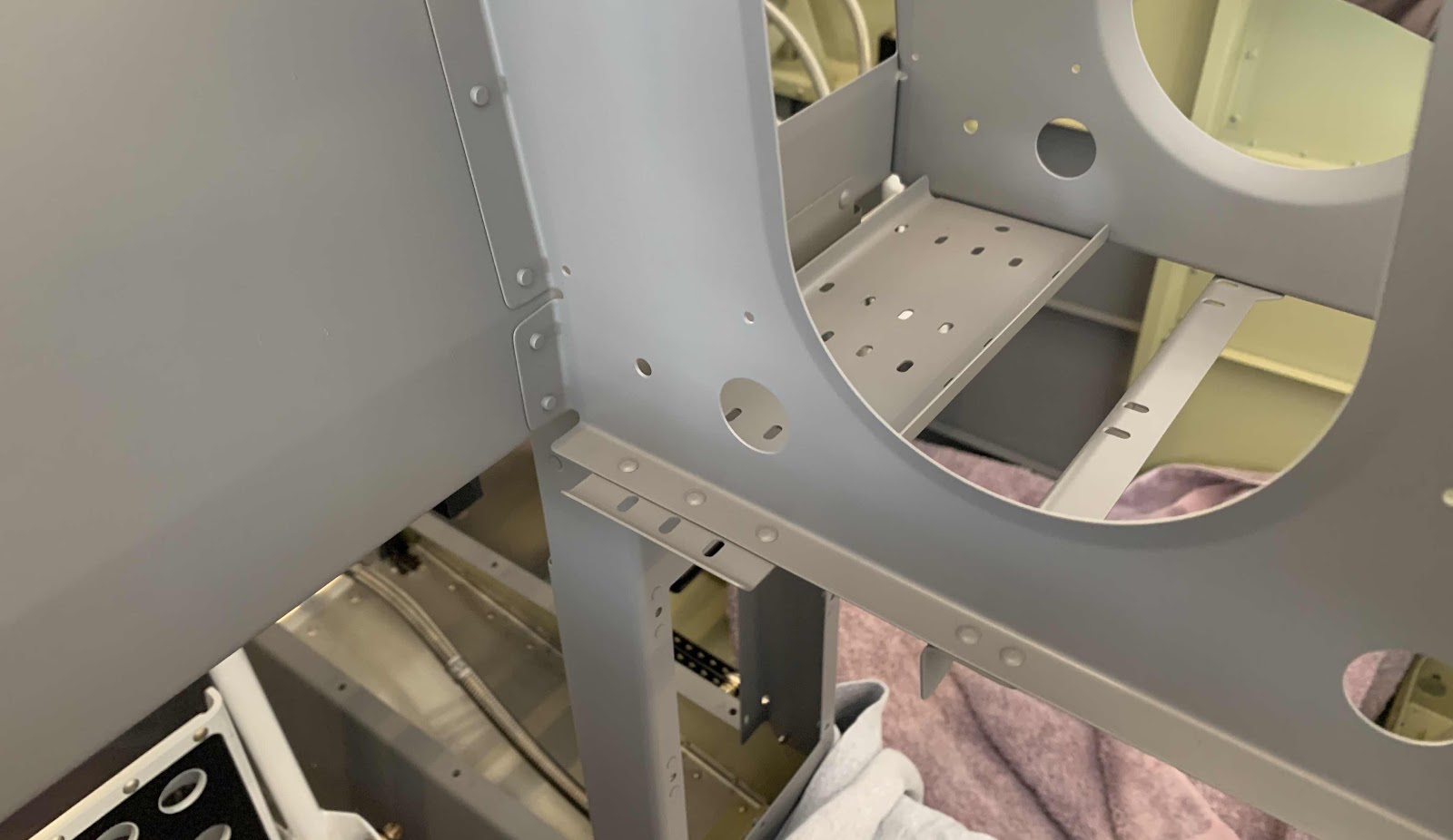
So, now that the instrument panel was installed, I came back to this Section to complete these few steps. First, I separated the F-14186-L & -R NACA Vent Brackets. Here are the Brackets after I separated them, deburred the holes and cleaned the edges. They are now awaiting treatment with Alumiprep, Alodine and Akzo primer.
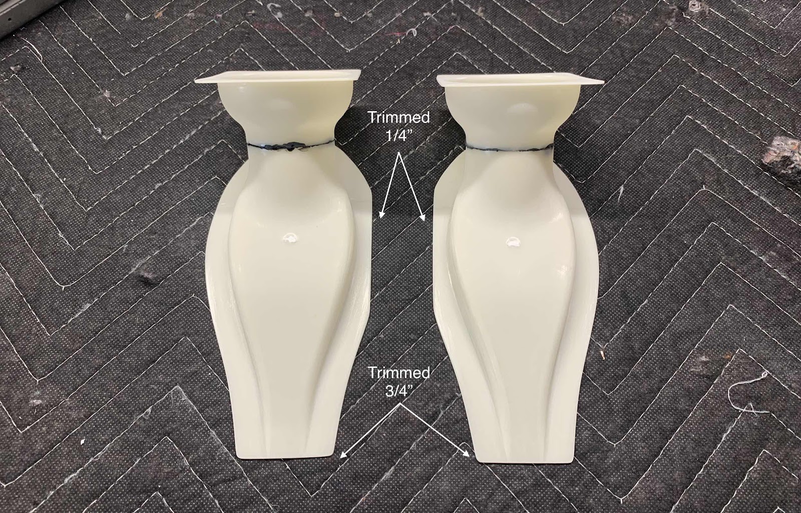
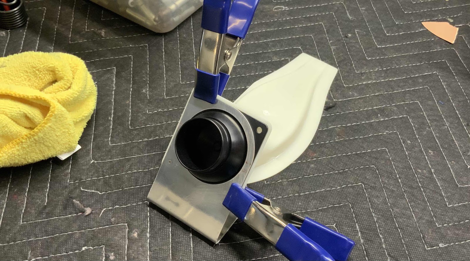
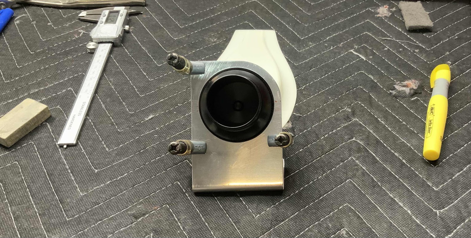
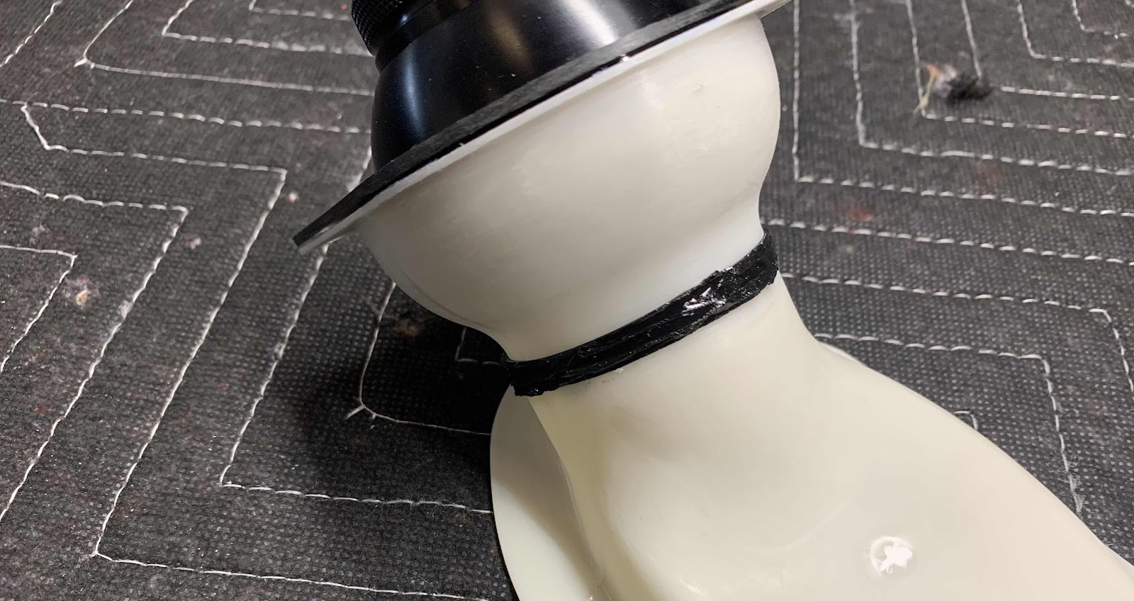
The note didn’t necessarily apply to separating the NACA Vent Brackets, but will definitely apply to the VENT SV-10 Fresh Air Vents. First, the Fresh Air Vents had to be trimmed as indicated in the picture below. I measured the correct trim lines and marked them with a Sharpie. I used a belt sander to remove a majority of the material and 320 grit sand paper for the final trim
I’m sure this wasn’t completely necessary, but I clamped the two Fresh Air Vents together to make sure they were the same.
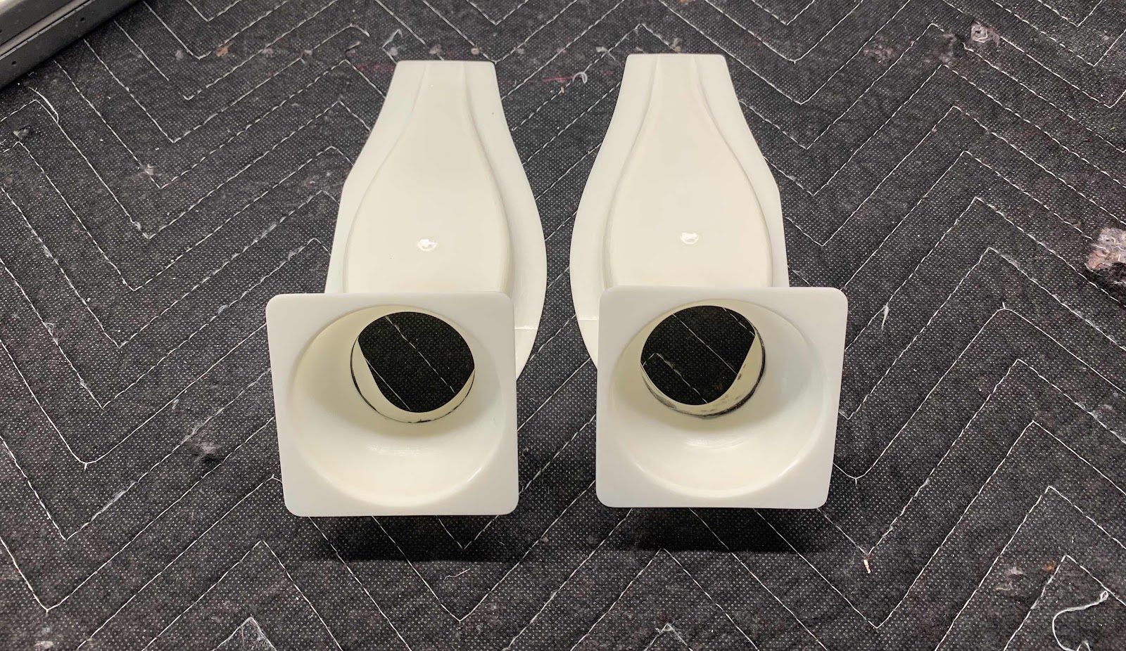
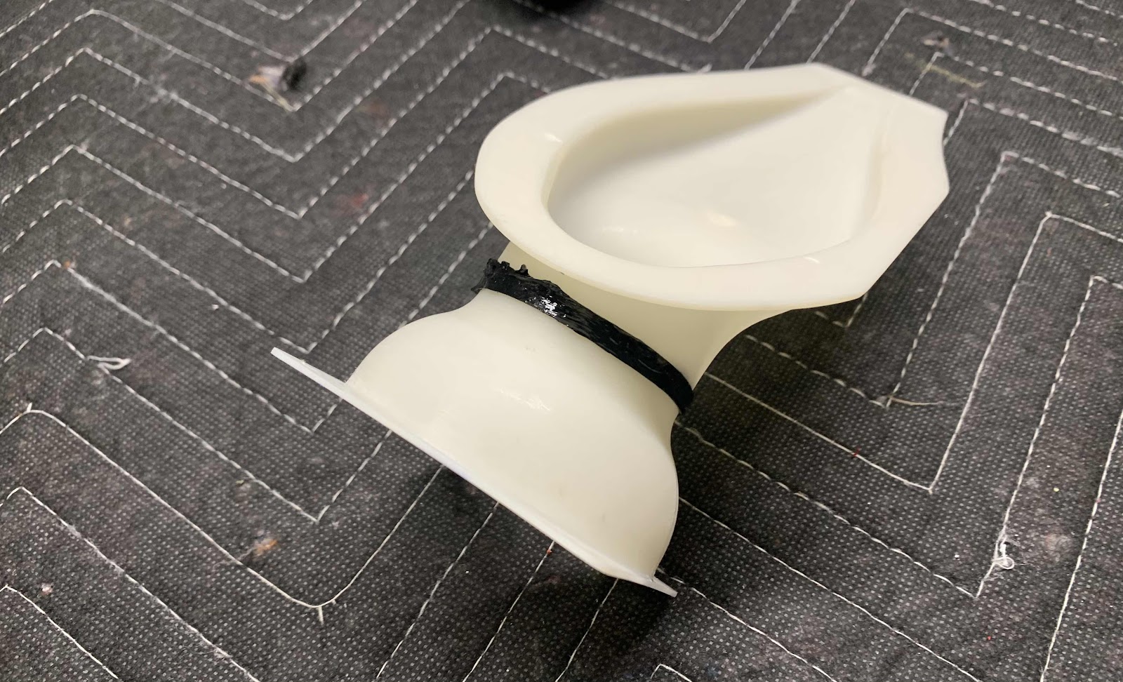
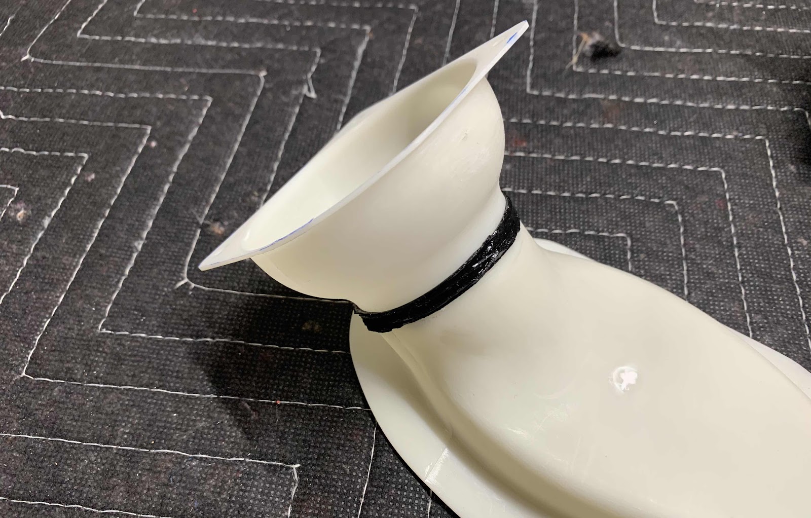
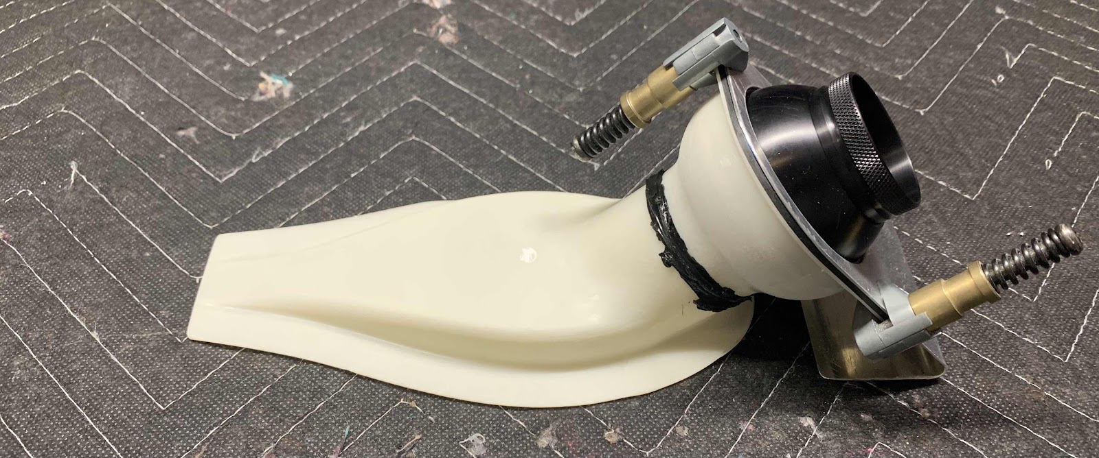
Now, in preparation of applying silicone adhesive and paint, all the surfaces of the two Vents were sanded until there were no shiny areas remaining. Here they are. I still need to apply additional silicone around the black “rings” to fill in some gaps from when the parts were manufactured. After that, they will be ready for assembly and installation on the airplane.
Sunday, April 19, 2020
Saturday, April 18, 2020
Fuselage, Upper FWD Fuselage, (Part 21)
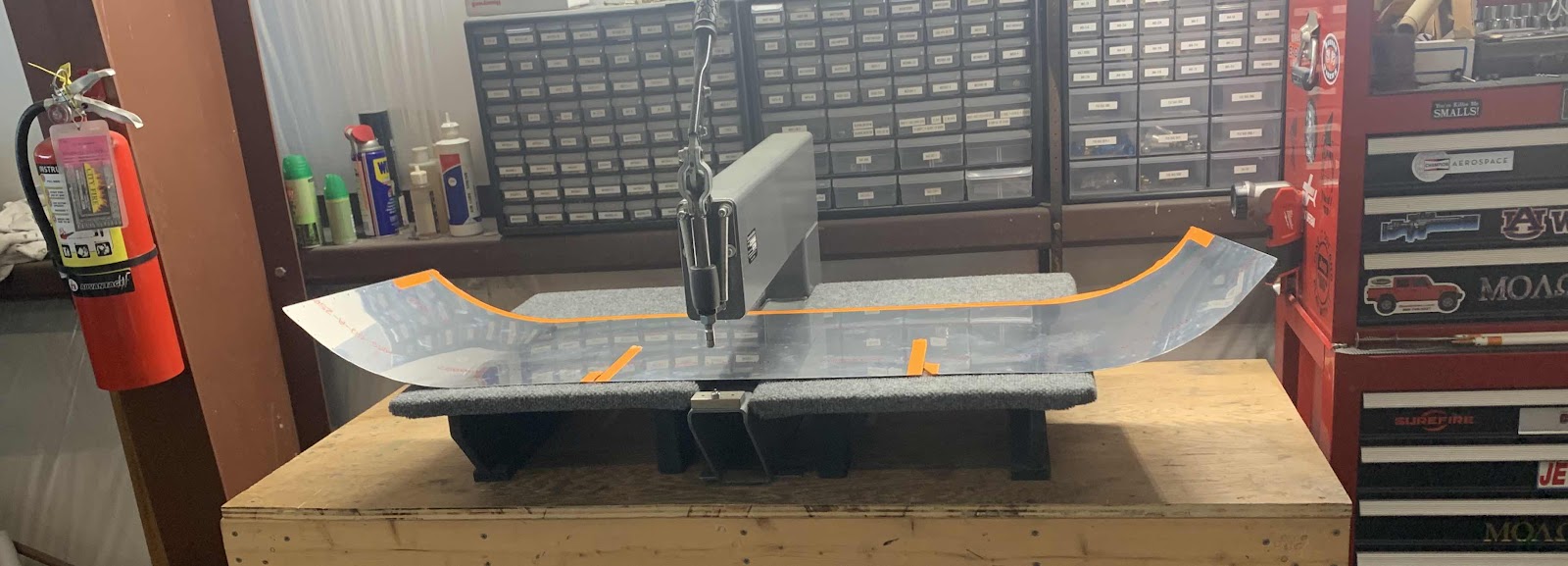
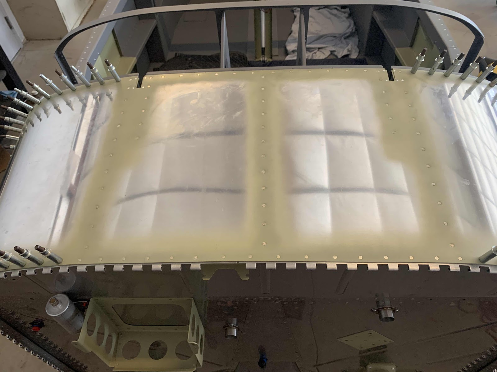
Today’s session was started by dimpling the F-01471 Forward Top Skin. As shown in the picture below, I used my DRDT-2 to dimple all the holes in the Skin.....except for the ones marked with the orange tape. They will get dimpled and/or countersunk in a later step.
Not the best picture, but the Skin below has been completely dimpled.....except for the holes marked with the orange tape in the picture above.

Next on the list is to match-drill the holes in the F-14134A-R (short) and F-14134A-L (long) Cowling Hinge Shims, the FF-00006A (long) and FF-00006C (short) Cowling Attach Piano Hinges and the F-01471 Forward Top Skin.
It goes like this:
1. The Forward Top Skin and Cowling Hinge Shims were clecoed to every hole in the Firewall flange.....then to all the remaining holes in the Forward Top Skin to the Substructure (starting from the center of the Skin working outward).
2. The Cowling Hinge Shims were gently bent to approximately match the curvature of the Forward Top Skin forward edge
3. The three clecos (per side) directly outboard of the the reference holes on the Cowing Attach Piano hinges were removed. (Index holes are located in the center of the assembly).
The plans have the following note in BOLD:
NOTE: Verify that the reference line on the hinge remains parallel to the forward edge of the side skin during drilling.
Work from the skin centerline outbd, clamp and cleco along the way.
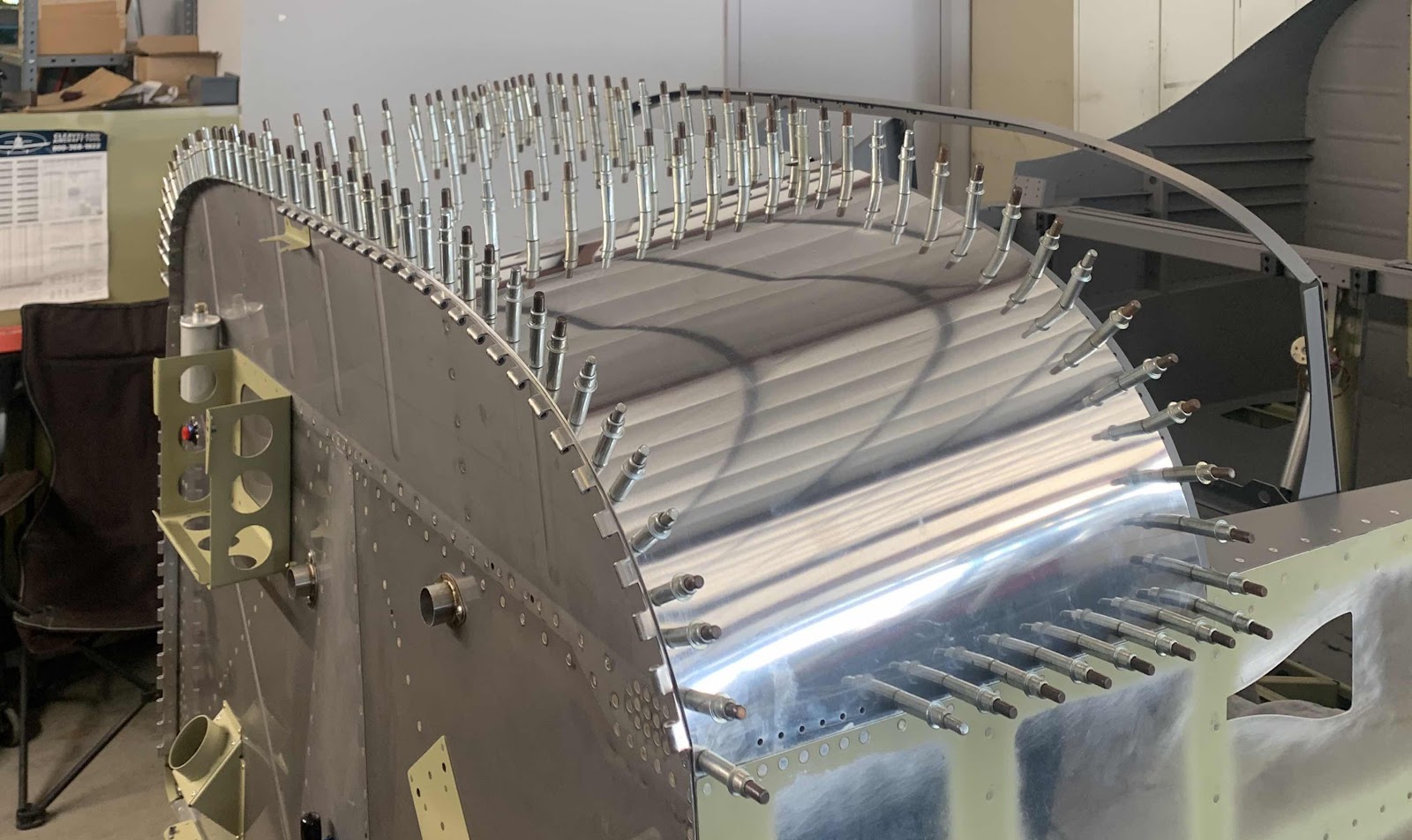
Once all that was done, it’s time to start match-drilling. The process starts at the top center and progressing moves outward using the holes in the skin, firewall flange, and shims as guides to match the holes in the Cowling Attach Piano Hinges. I used a small 1” clamp next to each hole as it is drilled and installed a cleco into each hole. I continued this method and match-drilled the remaining hole around the Firewall.
Here is a couple pictures of the completed Hinge on the left side (right as you look at it).
Thursday, April 16, 2020
Fuselage, Upper FWD Fuselage (Part 20)
In Part 19, I mentioned the AN43B-16A Release Pins would be modified. The picture below shows the release pins after they were modified according to the plans. First, I used my cut off wheel to remove all up three threads. Then, I used a belt sander to taper the ends as shown below. Lastly, I used a Scotchbrite wheel to polish the ends as directed by the plans. I will prime the Release Pins in a later session.
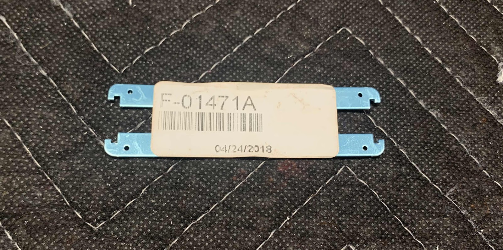
These are the F-01471A Skin Doublers.

The four holes on each Doubler were countersunk for the head of an AN426AD2-2 rivet (these dudes are tiny)! Then, I separated the Doublers and cleaned the edges. They are ready to be treated with Alumiprep, Alodine and Akzo Primer.

To go along with the Skin Doublers, the F-01471 Forward Top Skin was also countersunk for the same tiny AN426AD2-2 rivets. Here is one side of the Skin after being countersunk. The opposite side was completed the same way.

The are the F-14134A-L & -R Cowling Hinge Shims.

The were separated, holes deburred, and edges cleaned. They are also ready to be treated with Alumiprep, Alodine and Akzo Primer.
Wednesday, April 15, 2020
Fuselage, Upper FWD Fuselage (Part 19)
I started today by installing the SPRING 00001 Gas Spring for the Canopy.
From the plans excerpt, the install looks like this. I will attach a picture of my completed install in the next few days (forgot to take a picture of the Springs).
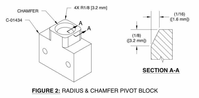
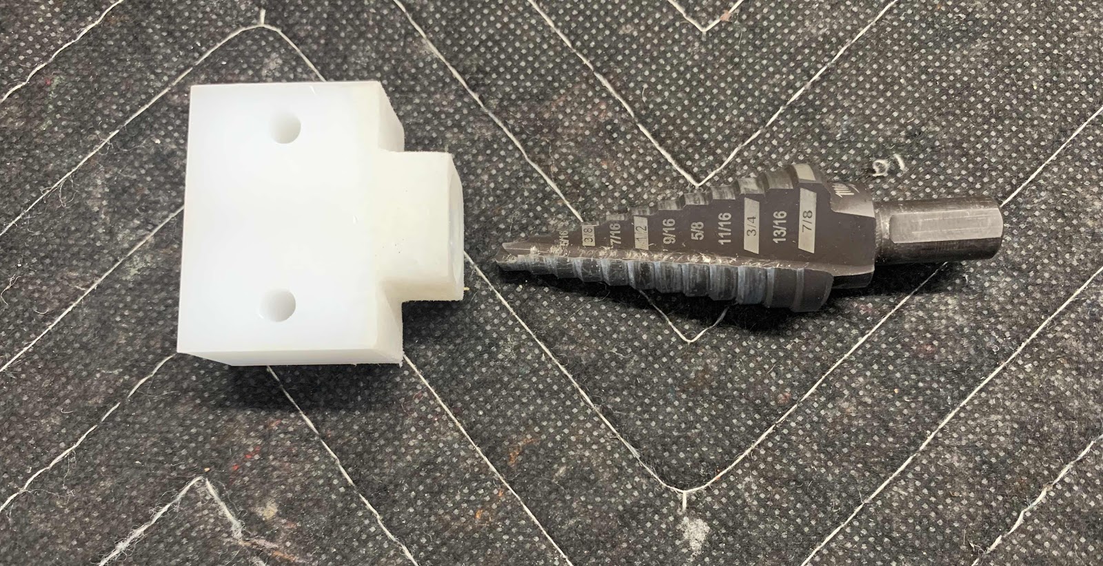
Now, I will start preparing parts that make up the Canopy Release or “Jettision”. The white plastic block below is the C-01434 Canopy Release Pivot Block. It needed two things done to it as described in the plans excerpt:
First, the four edges were rounded and then the interior portion of the center hole had to be chamfered. The edges were rounded very easily with a small sanding block and 220 grit sandpaper. The chamfered center hole initially was a pain in the a**. The plans recommend using a razor knife. I tried this method, but it looked like crap. So, I came up with something different. I used a step bit and turned it by “hand” to get the desired result. I think it worked out pretty good.
The ultimate goal is to have the Pivot block “cover” the weld on the WD-619 Canopy Release Assembly as shown below. Here, you can see the Pivot Block sitting flush on the base of the Release Assembly.....like I said is the goal of the chamfer in the first place.

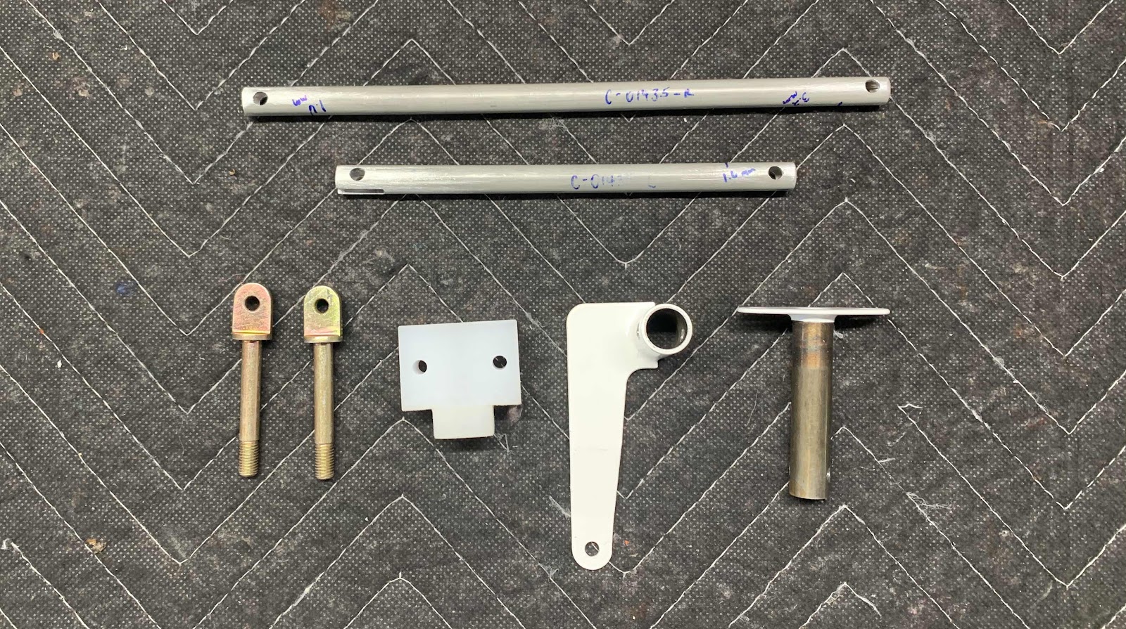
These are all the pieces that make up the Canopy Assembly Release Mechanism. The two F-01435-L & -R Canopy Release Pushrods had to be fabricated from raw AT6-058X3/8 tube. The -R is Pushrod is 8 1/2” and the -L is 6 1/32” and each has #12 holes drilled through each end. Also shown are the two Release Pins (that will be modified later), the previously discussed Canopy Release Pivot Block, the WD-618-1 Canopy Release Assembly and the WD-619 Canopy Release Assembly.
The two Canopy Release Pushrods had to be modified with a “notch” on each end. Here is one of the “notches” that was completed. First, I took the measurements from the plans and marked it off on the Pushrod. Next, I used my Milwaukee rotary tool with a small cutoff wheel to cut the top and bottom lines. I broke off the remaining piece of aluminum and used a small file (that just happened to be the correct width required for the “notch”) to shape the “notch”. Finally, I used 220 grit sandpaper to smooth everything out. The result turned out pretty good.

Here is another view.

This is the small file set that I used to make the “notches” on the Pushrods purchased from the Home Depot. There are two files I took out of the package. These are the two files I used to prepare the Pushrod “notches”. Each end of the Pushrod had different sized “notches” and the two files worked perfectly for each respective end.
I will prepare the remaining three “notches” on the two Pushrods and show the results once they are primed, painted and completed.
Tuesday, April 14, 2020
Fuselage, Upper FWD Fuselage (Part 18)
In Part 17, I clecoed the F-01494C Wiring Channel and F-01494D Cable Support Bracket to the bottom of the F-01494-R & -L Instrument Panel Stand-Offs. Today, I riveted them into place using AN470AD3-3.5 (plans called for 3-3, but they measured a little to short). Once the parts were riveted, I sprayed the manufactured heads of the rivets with the SEM medium gray paint. This is the right side.....
.....and the left side. All 10 rivets were easily installed with a hand squeezer.
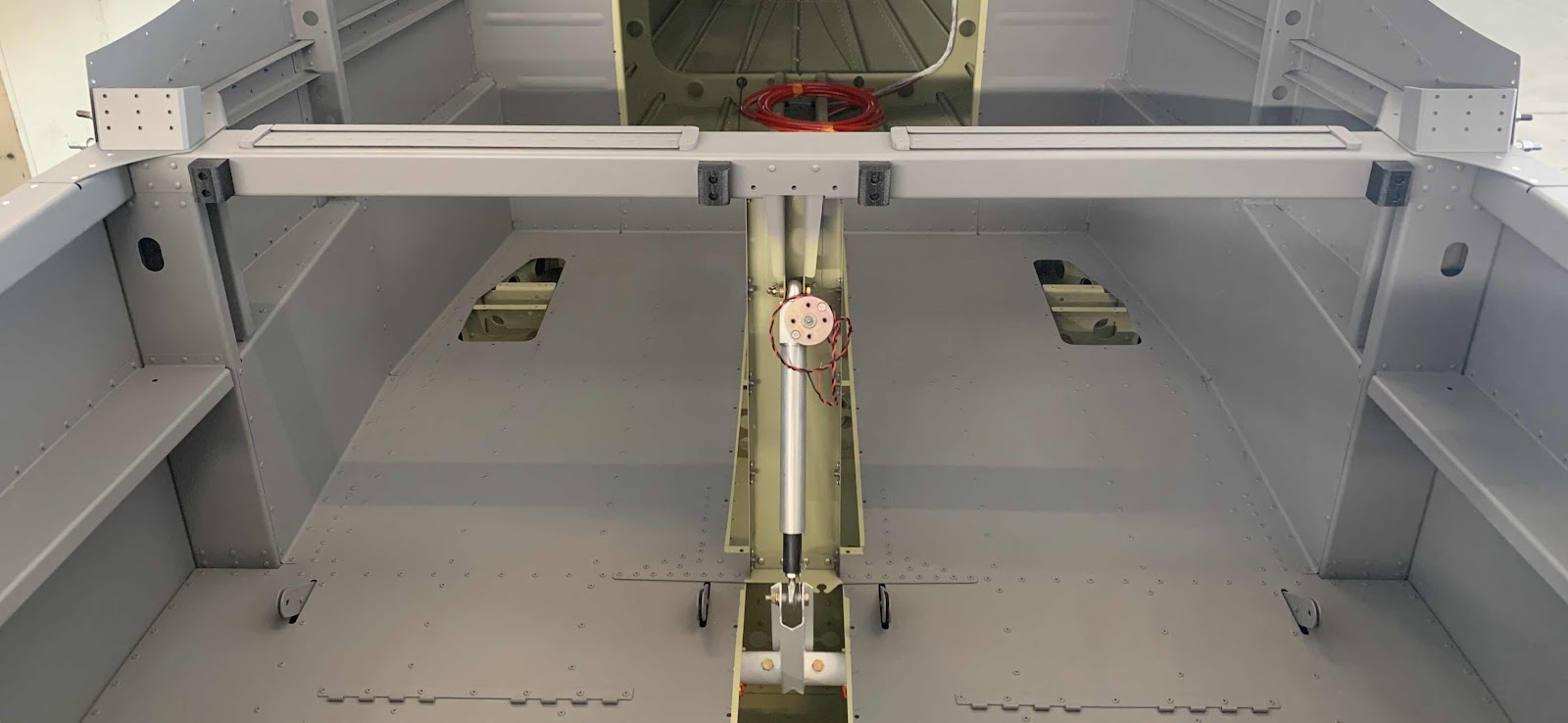
In order to paint the F-01405F Mid Fuselage Brace, I previously removed the four black F-14144 Seatback Guides. Now that the Brace has been painted, I re-installed the four Guides as shown below.
Lastly, I installed the Instrument Panel Frame Assembly to the airplane as shown here in the planes excerpt.
This install also included 12 K1000-06 nutplates on the Frame using 24 AN426AD3-4.5 and four AN426AD3-5 rivets on the Frame to F-01476 Instrument Panel Attach Plates. Here is the completed install of the Panel Frame. I will eventually paint the forward and rear sides with the gray paint to cover the rivets and nutplates.

*****Since completing the work contained within this post, I have removed the stock Cable Support Bracket***** and installed a new custom bracket. For details, please see:
Modifications and Upgrades, Cable Support Bracket
Subscribe to:
Posts (Atom)