Friday, July 31, 2020

Fuselage, Rollover Structure (Part 4)

In this session, we worked on the AFT Roll Bar Assembly.  Shown below is the C-01432 Bushing Doubler clecoed to the left side of the AFT assembly (looking forward)…..

…..the Doubler riveted into place and the BUSHFBZ.502X.377X.375 Bushing installed…..

…..and the C-01433 Bushing Cover riveted into place.

The other side of the Assembly is the same.  Here is the right side of the AFT assembly (again, looking forward).  Here is the Bushing Doubler clecoed into place…..

…..the Doubler riveted into place and the bushing installed…..

…..and the Bushing Cover riveted into place.

Thursday, July 30, 2020

Fuselage, Aileron & Elevator Systems (Part 2)

Fuselage, Rollover Structure (Part 3)

After all those #40 holes were made to be #30 holes, the FWD and AFT Roll Bar Assemblies were separated to begin some riveting.  Pictured below is the FWD assembly.  As I mentioned in Part 2, the Inboard and Outboard Roll Bar Straps can now easily be seen in the next two pictures…..now that the two halves have been separated.

Here is a close up of the center section of the FWD assembly.

This shows the opposite side of the center section with several 426 rivets were installed.

This is the left (pilot) side…..

…..and the right (copilot) side.  Again, 426 rivets are used in this location because the canopy will close onto this assembly.

Now, like I mentioned in Part 2…..here are the 426 rivets I had to use on the inboard (lower) side of the assembly.  Again, these holes were mistakenly countersunk…..and per the plans, 470 rivets should have been used in the location.  Despite the error, it turned out pretty nicely.  I’ll take it and build on.


Here is a view of the completed FWD Roll Bar Assembly after riveting the Inboard and Outboard Roll Bar Straps.

Wednesday, July 29, 2020

Fuselage, Rollover Structure (Part 2)

I forgot to take pictures of the initial steps in this section, such as the separation of parts, deburring, countersinking, etc.  Additionally, all of the pictures in this section are after the parts were treated with alumiprep, alodine and Akzo primer.

This is the “front 1/2” of the roll bar structure.  Specifically, in the first picture, is the F-01431A-FL (Front Left) and F-01431A-FR (Front Right).  These two pieces are connected together using a F-1231E Roll Bar Splice Plate.  The three pieces were riveted together using 24 AN470AD4-5 rivets.  This is now known as the “FWD Roll Bar Assembly”.

(Note:  The F-10431A-AL (Aft Left), F-01431A-AR (Aft Right) and second F-1231E Roll Bar Splice Plate were assembled in the same manner using 20 AN470AD4-5 rivets…..the remaining four rivet locations will be used later.  This is now know as the “AFT Roll Bar Assembly”.)

Here is the shop head side of the rivets…..

…..and the manufactured side of the rivets.

*****Note:  In the three pictures above, you will notice I also countersunk the inboard (lower) holes on the FWD Roll Bar Assembly.  I did this in ERROR!  The plans only call for the outboard (upper) holes to be countersunk (because the canopy and baggage area windows will rest on top of the roll over assembly).  So, instead of 470 rivets in the lower holes, I will have to use 426 rivets.  Not a big deal and the only thing I lost…..the time countersinking the holes.  More on this error in the next post.*****

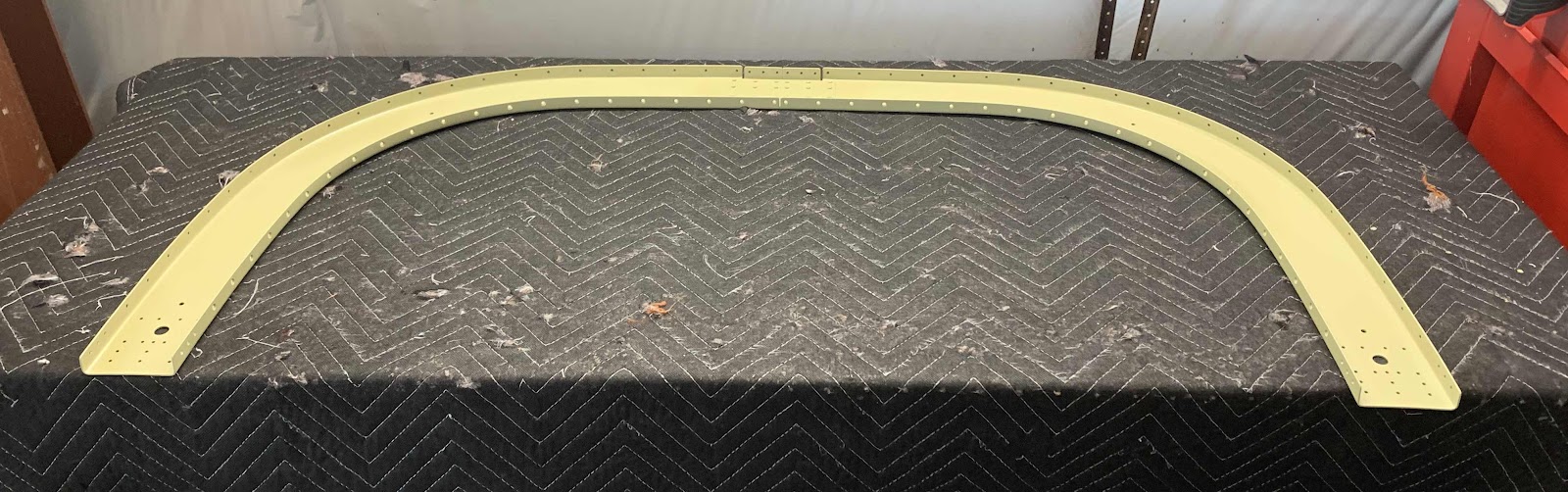
The next step was to cleco the F-01431B Outboard Roll Bar Strap to the FWD Roll Bar Assembly and the F-01431C Inboard Roll Bar Strap the AFT Roll Bar Assembly.  (You will be able to see all these parts with a little more clarity when I rivet them together in the next post).

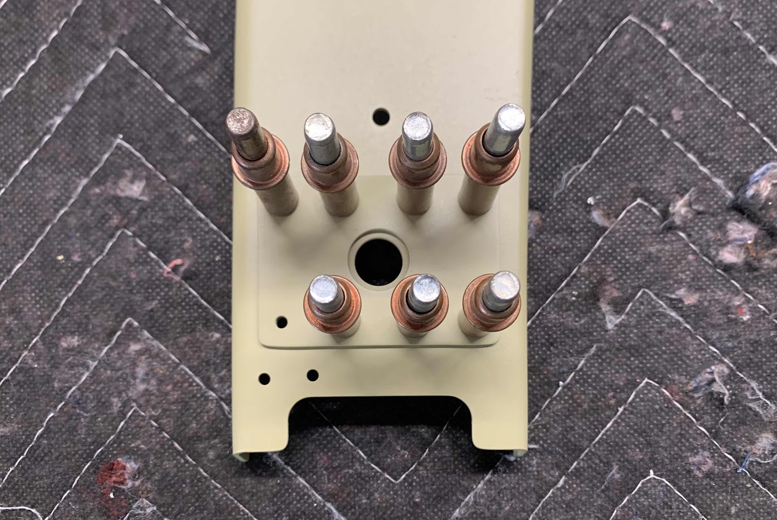
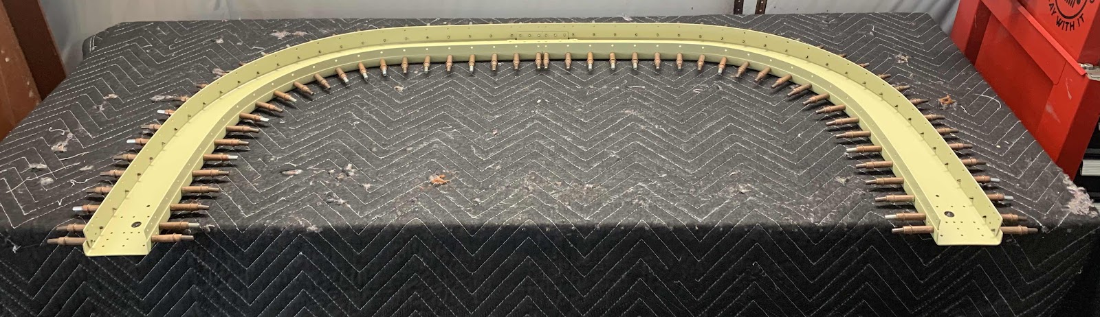
Once clecoed together, all the #40 holes (silver clecos) had to be final-drilled to #30 holes (bronze clecos).  In the picture below, half of the final-drilling is complete…..it’s ALOT of holes!!!!

Additionally, the F-01431D Window Shims were clecoed to the AFT Roll Bar Frame Assembly and Outboard Roll Bar Strap.  In the picture below, you can see the window shims on the bottom side and in the upper center of the assembly.  (They are actually not primed yet).

Just another view of everything clecoed together.

Saturday, April 25, 2020

Fuselage, FWD/MID Side Structure (Part 41)

I previously delayed the next few steps from when I was working on Section 29 in early January (reason for the gap in this and the previous Part) for a couple reasons.  One:  I ordered, and was waiting on, the black aluminum vents from Van’s to replace the plastic ones from the kit. Two:  There is a note in the plans that says, “Delay the following steps until after the completion of Section 35 to eliminate the possibility of interference with the bottom of the instrument panel”.  

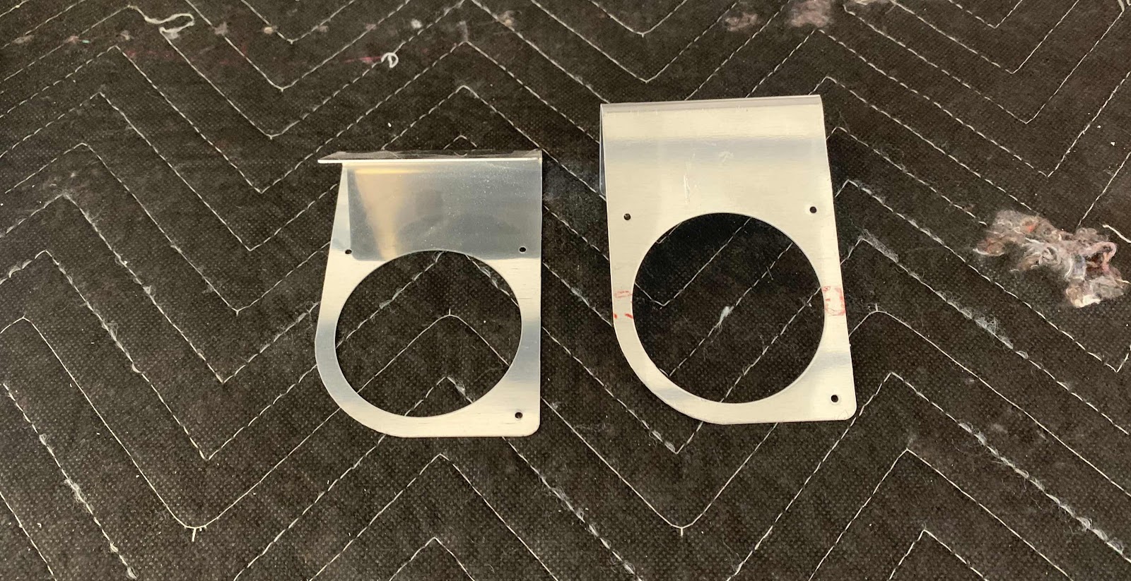
So, now that the instrument panel was installed, I came back to this Section to complete these few steps.  First, I separated the F-14186-L & -R NACA Vent Brackets.  Here are the Brackets after I separated them, deburred the holes and cleaned the edges.  They are now awaiting treatment with Alumiprep, Alodine and Akzo primer.
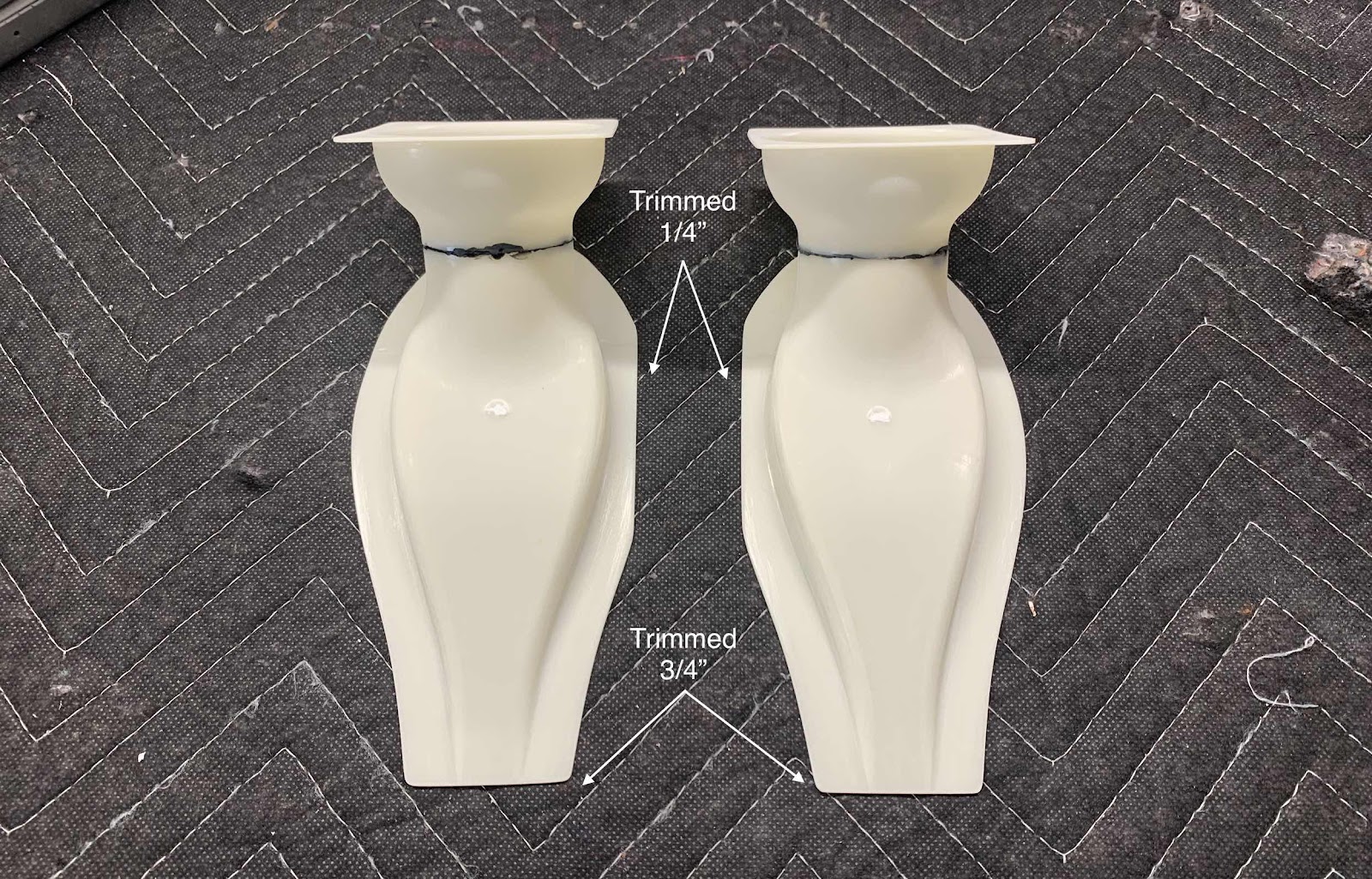
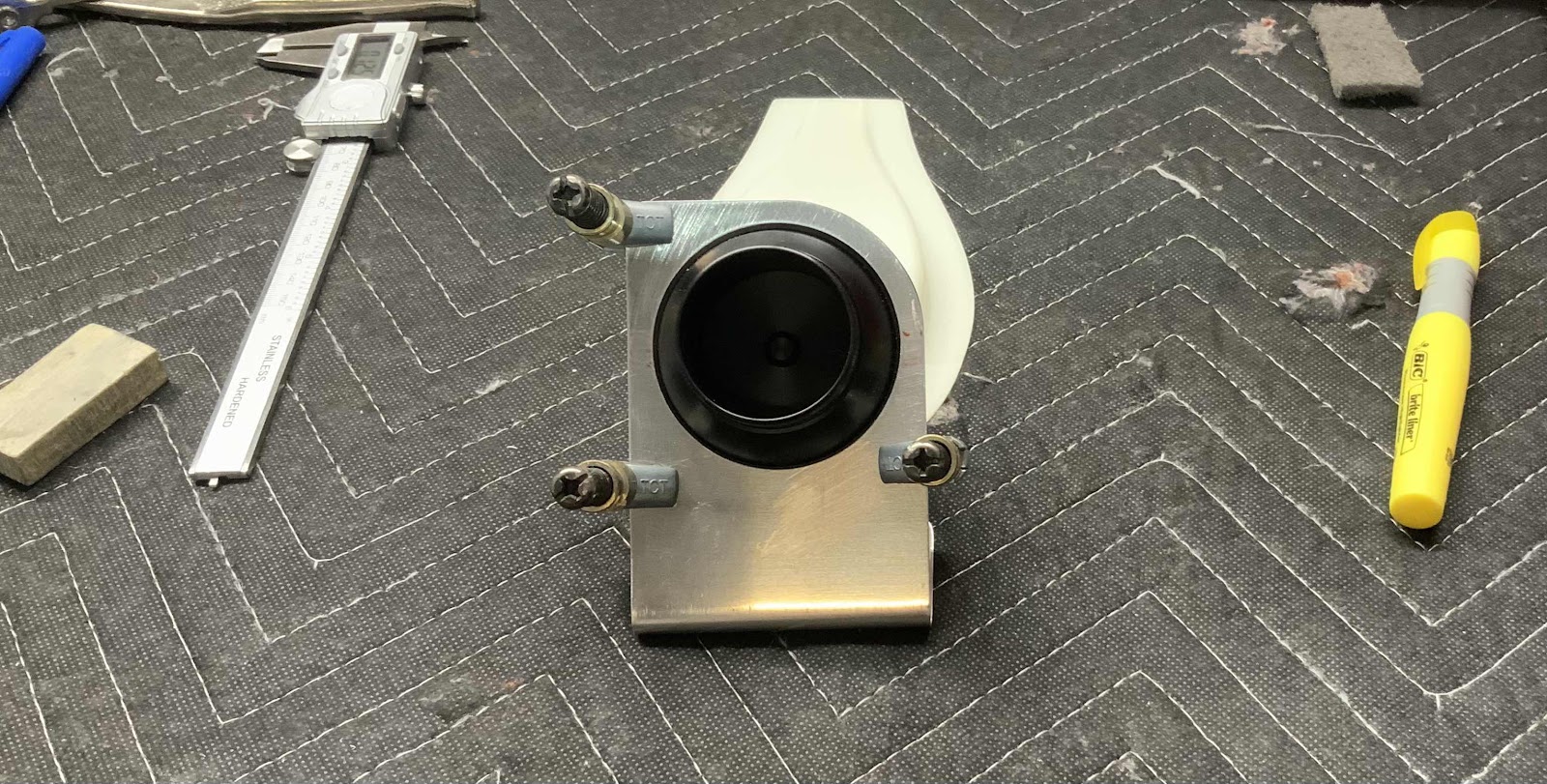
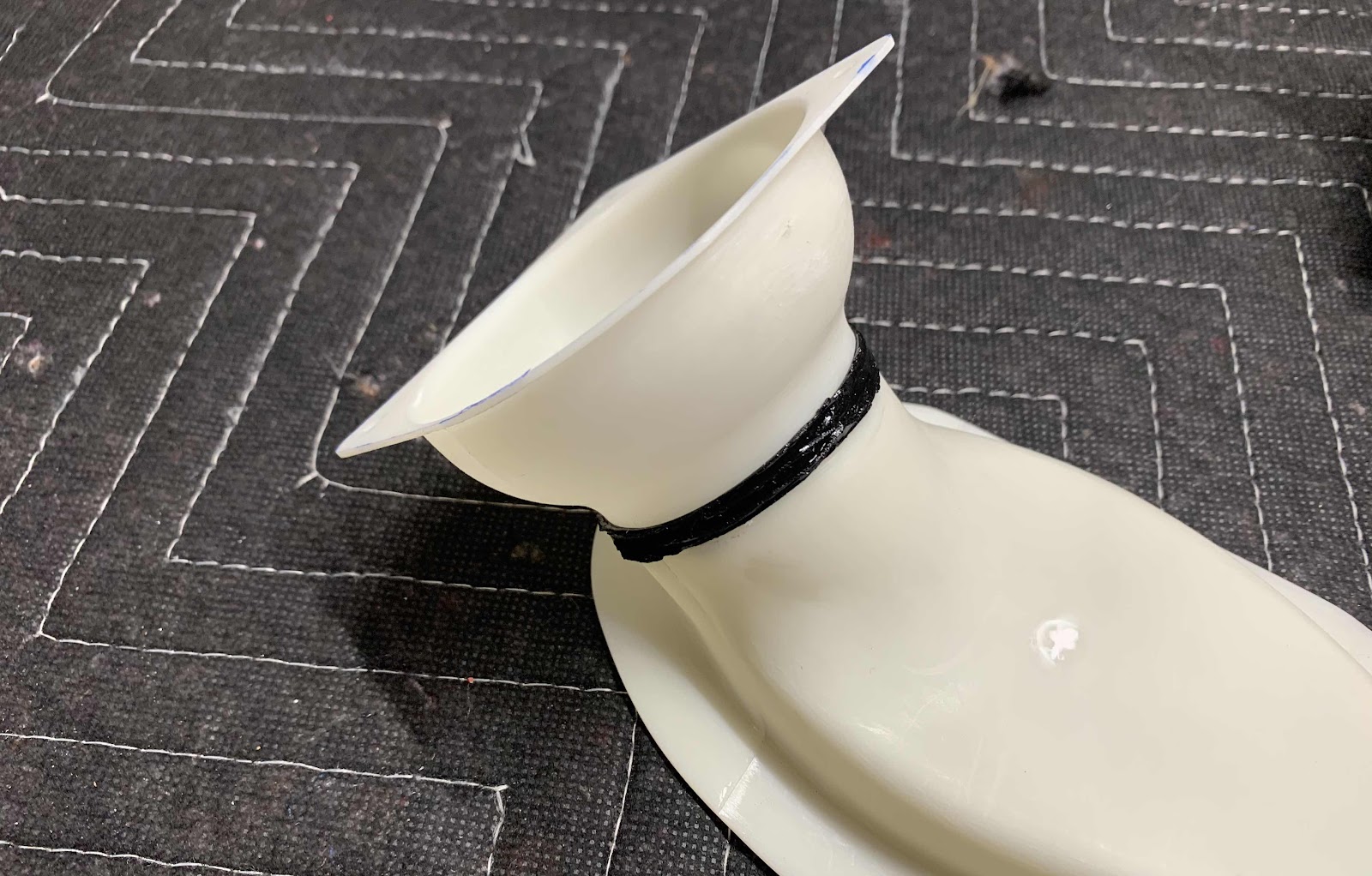
The note didn’t necessarily apply to separating the NACA Vent Brackets, but will definitely apply to the VENT SV-10 Fresh Air Vents.  First, the Fresh Air Vents had to be trimmed as indicated in the picture below.  I measured the correct trim lines and marked them with a Sharpie.  I used a belt sander to remove a majority of the material and 320 grit sand paper for the final trim
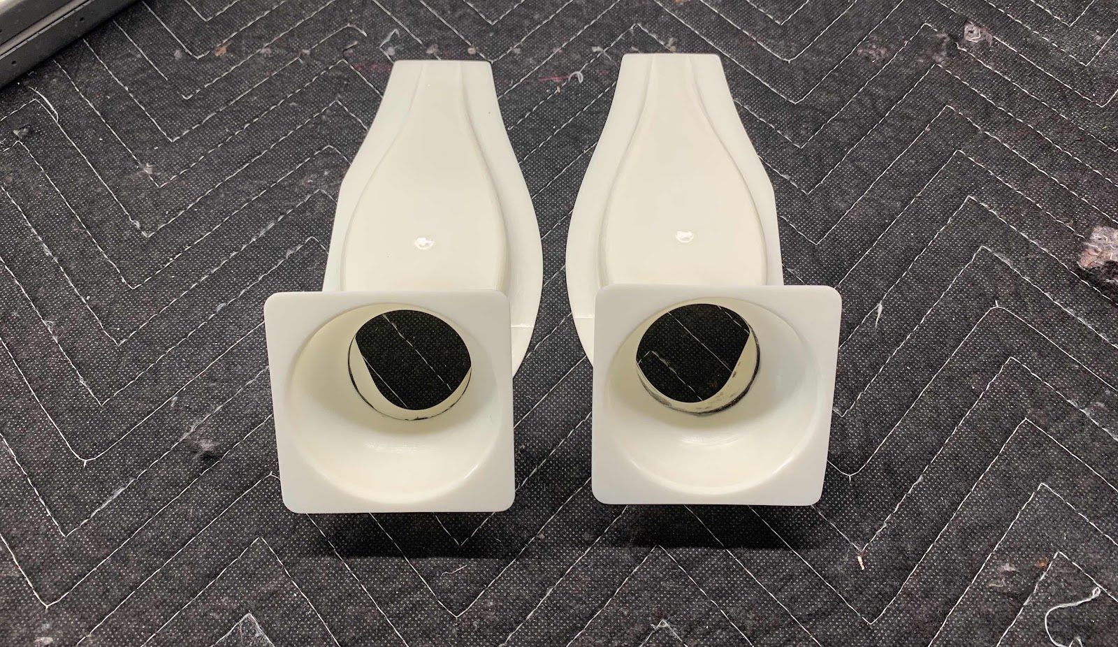
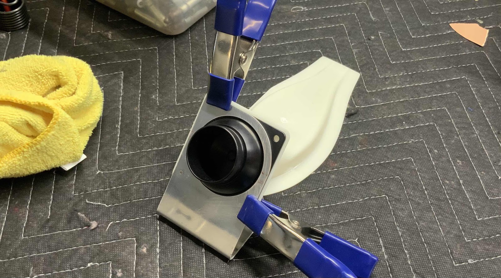
I’m sure this wasn’t completely necessary, but I clamped the two Fresh Air Vents together to make sure they were the same.

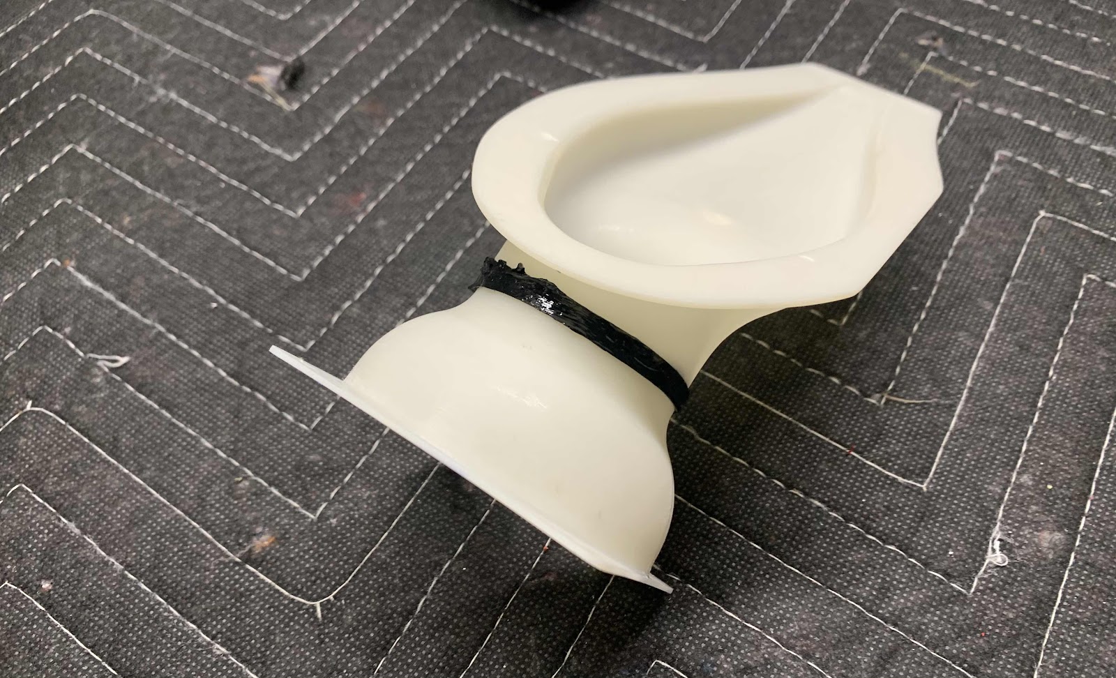
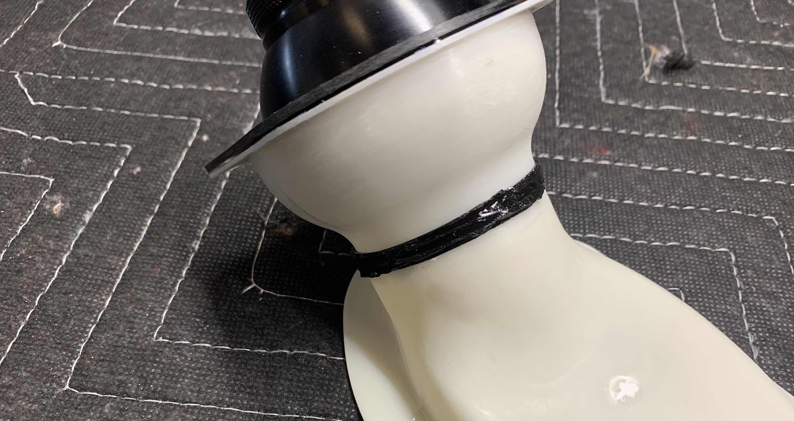
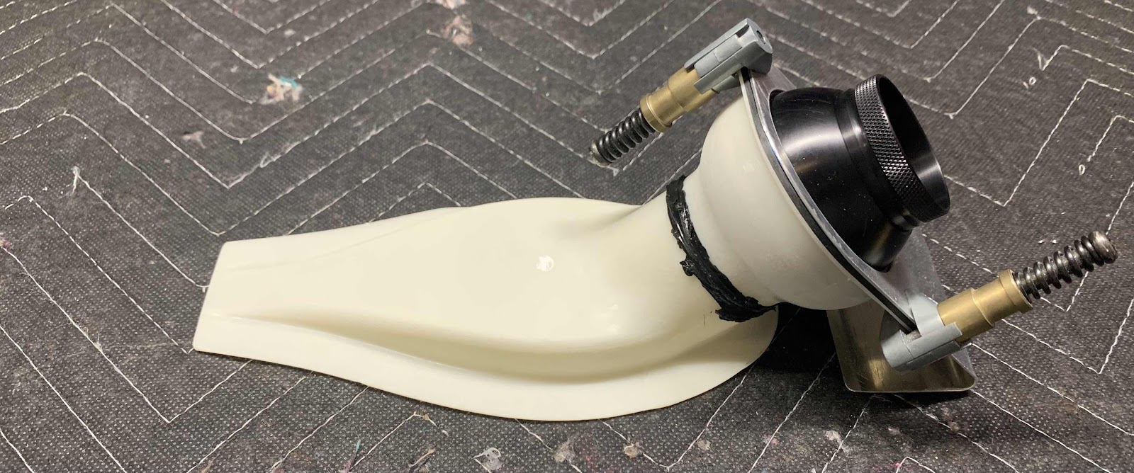
Now, in preparation of applying silicone adhesive and paint, all the surfaces of the two Vents were sanded until there were no shiny areas remaining.  Here they are.  I still need to apply additional silicone around the black “rings” to fill in some gaps from when the parts were manufactured.  After that, they will be ready for assembly and installation on the airplane.

Saturday, April 18, 2020

Fuselage, Upper FWD Fuselage, (Part 21)

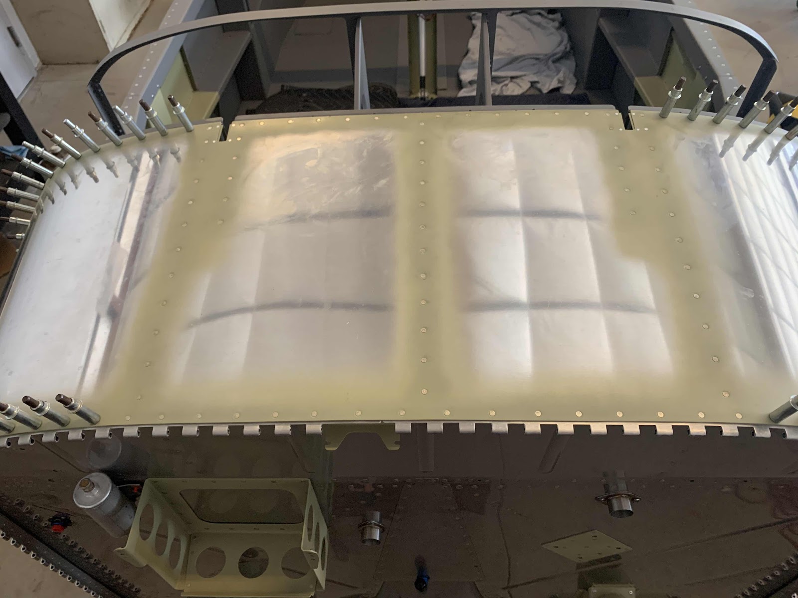
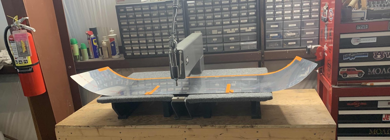
Today’s session was started by dimpling the F-01471 Forward Top Skin.  As shown in the picture below, I used my DRDT-2 to dimple all the holes in the Skin.....except for the ones marked with the orange tape.  They will get dimpled and/or countersunk in a later step.

Not the best picture, but the Skin below has been completely dimpled.....except for the holes marked with the orange tape in the picture above.

Next on the list is to match-drill the holes in the F-14134A-R (short) and F-14134A-L (long) Cowling Hinge Shims, the FF-00006A (long) and FF-00006C (short) Cowling Attach Piano Hinges and the F-01471 Forward Top Skin.

  
It goes like this:

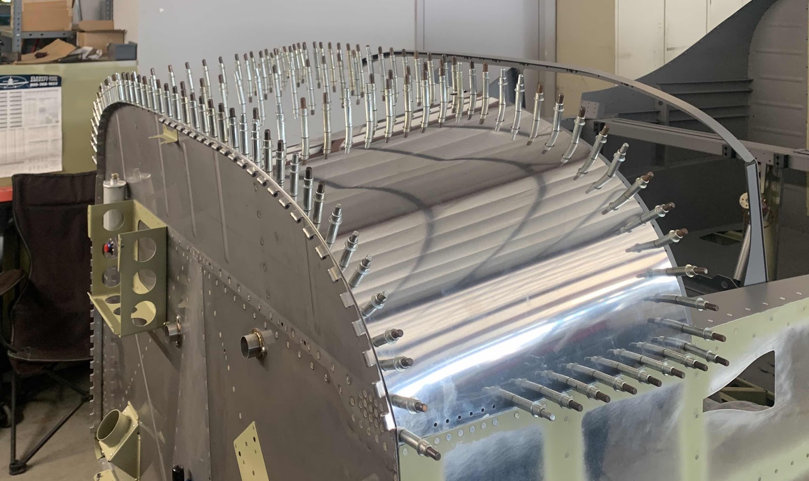
1.  The Forward Top Skin and Cowling Hinge Shims were clecoed to every hole in the Firewall flange.....then to all the remaining holes in the Forward Top Skin to the Substructure (starting from the center of the Skin working outward).

2.  The Cowling Hinge Shims were gently bent to approximately match the curvature of the Forward Top Skin forward edge

3.  The three clecos (per side) directly outboard of the the reference holes on the Cowing Attach Piano hinges were removed.  (Index holes are located in the center of the assembly).

The plans have the following note in BOLD:

NOTE: Verify that the reference line on the hinge remains parallel to the forward edge of the side skin during drilling.
Work from the skin centerline outbd, clamp and cleco along the way.

Once all that was done, it’s time to start match-drilling.  The process starts at the top center and progressing moves outward using the holes in the skin, firewall flange, and shims as guides to match the holes in the Cowling Attach Piano Hinges.  I used a small 1” clamp next to each hole as it is drilled and installed a cleco into each hole.  I continued this method and match-drilled the remaining hole around the Firewall.

Here is a couple pictures of the completed Hinge on the left side (right as you look at it).