Sunday, September 8, 2019

Fuselage, FWD/MID Side Structure (Part 2)

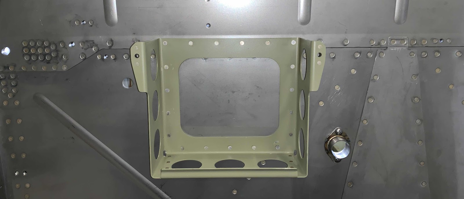
Today’s session looks like it’s “beef” up the area where the Wings attach to the Fuselage.  Pictured below is the F-01442 Lower Drag Fittings.  
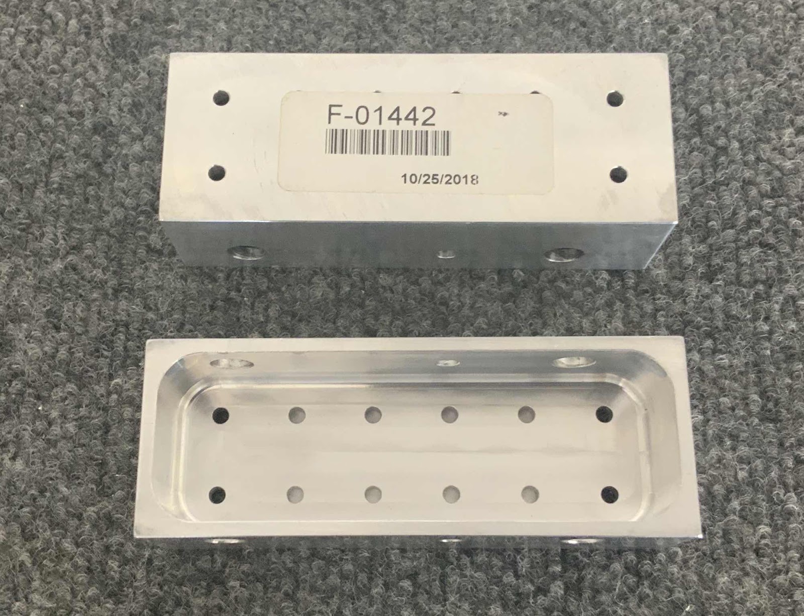
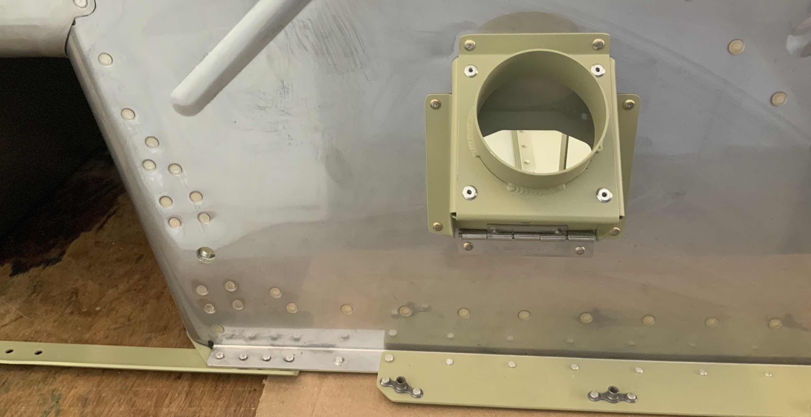
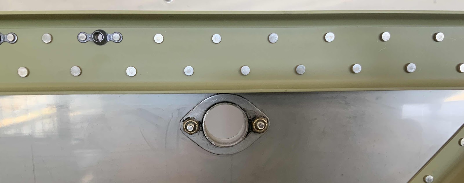
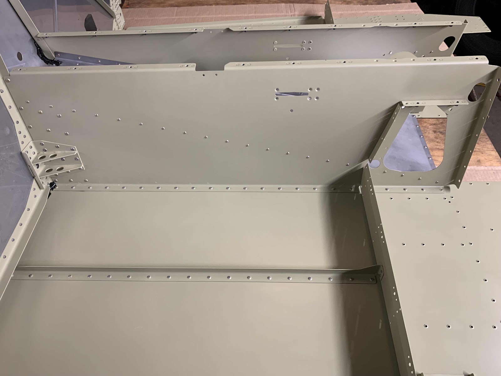
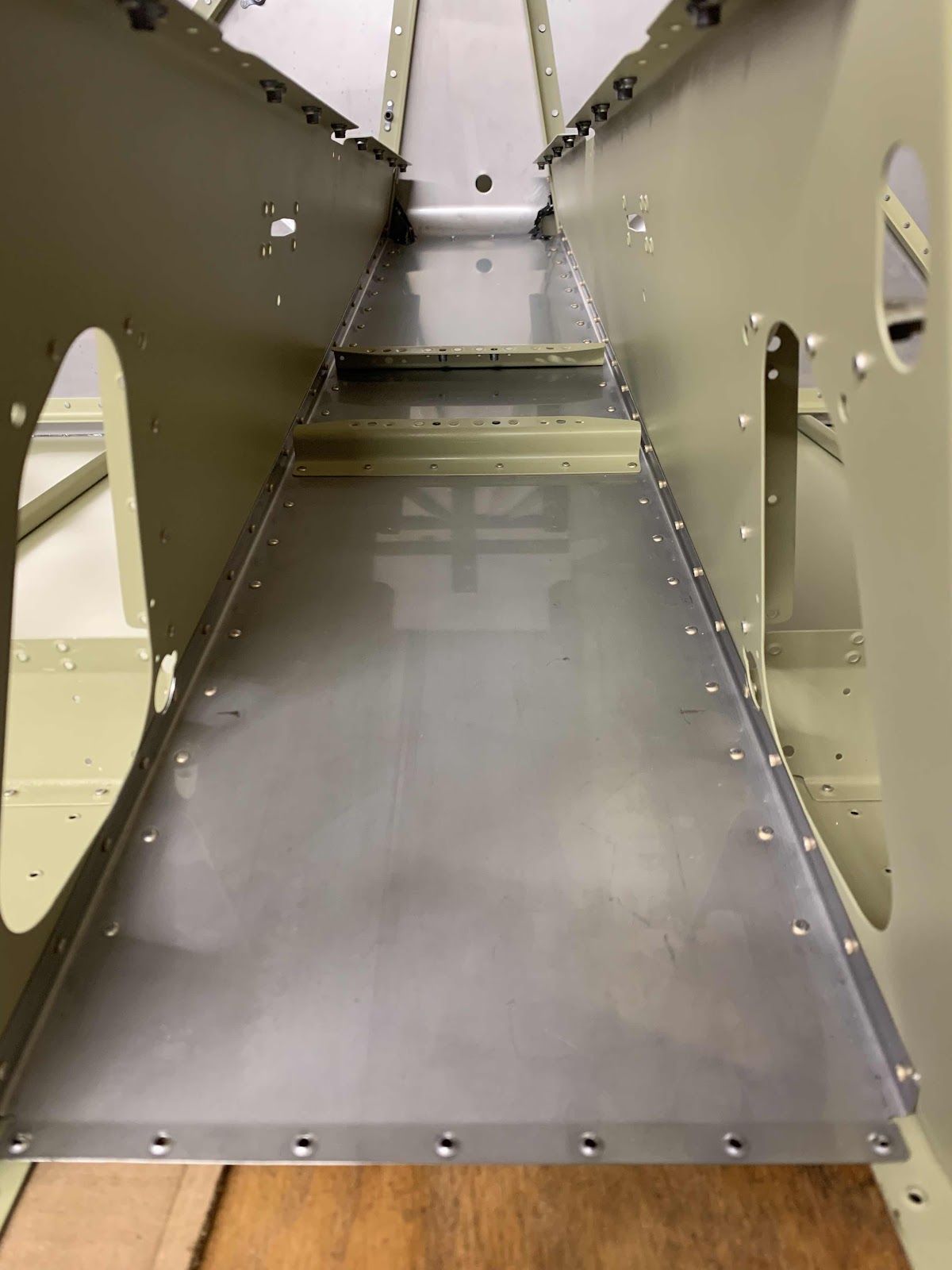
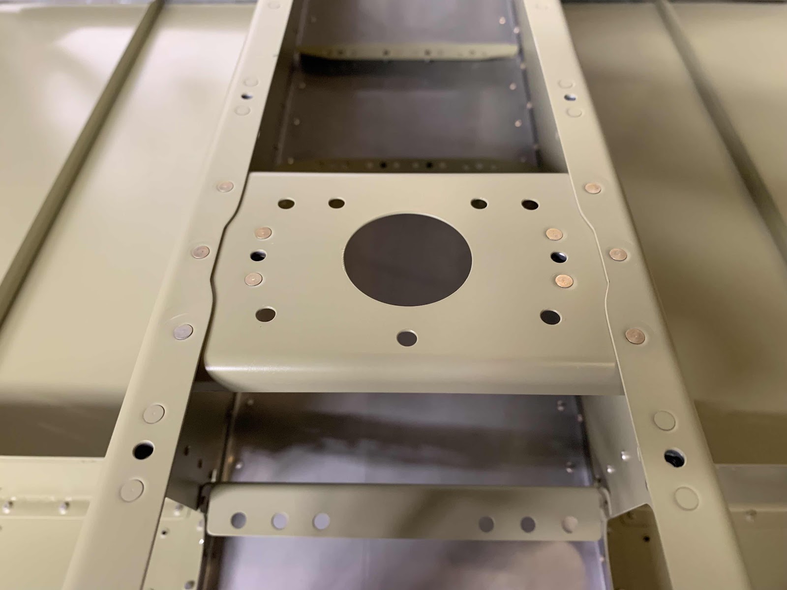
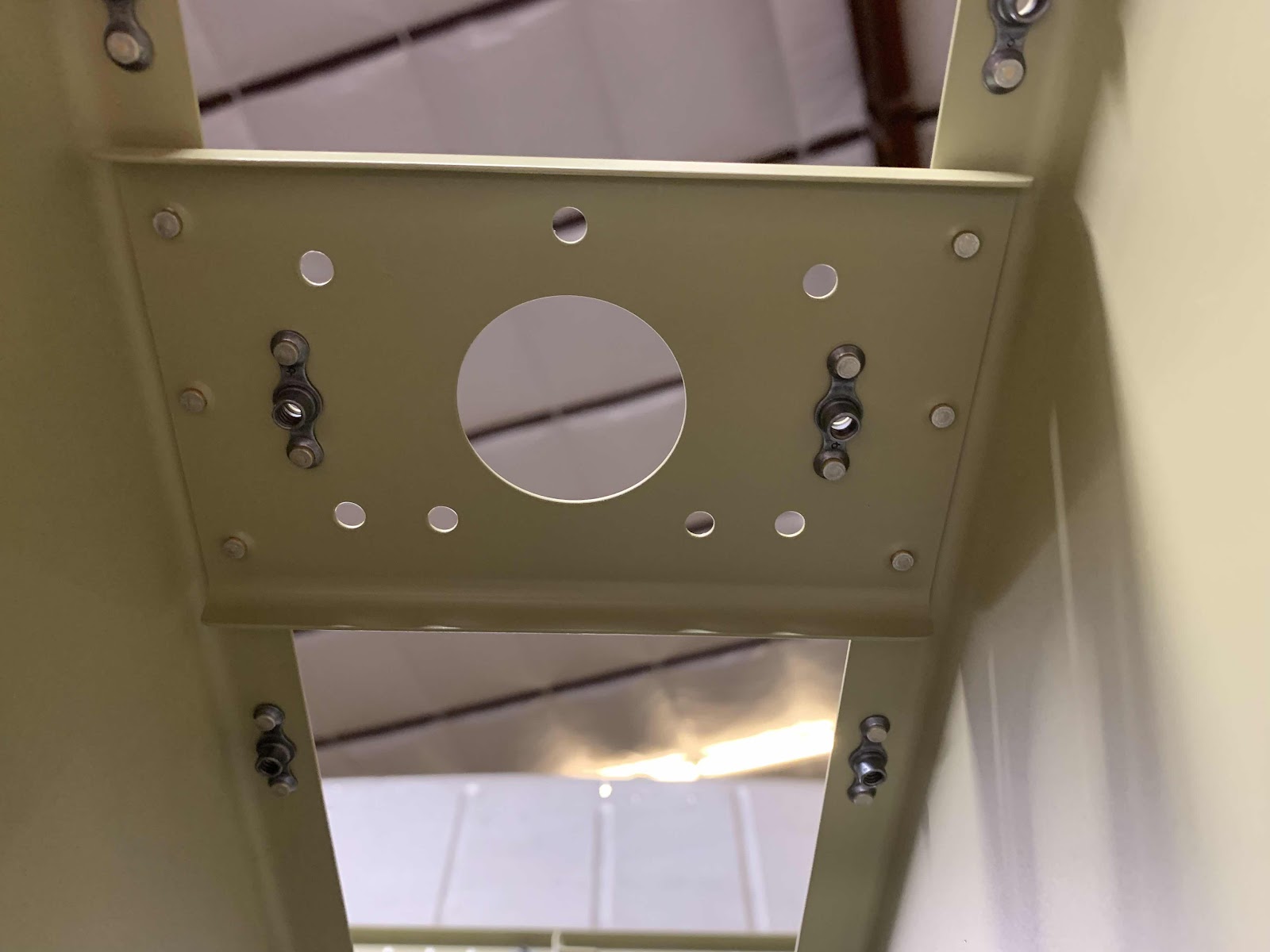
These two pieces get installed in the “lower” area between the Forward Fuselage Lower Structure and the Mid Fuselage Lower Structure as shown below.  The first picture is the left side.....

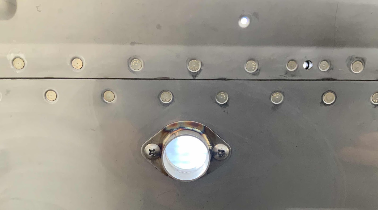
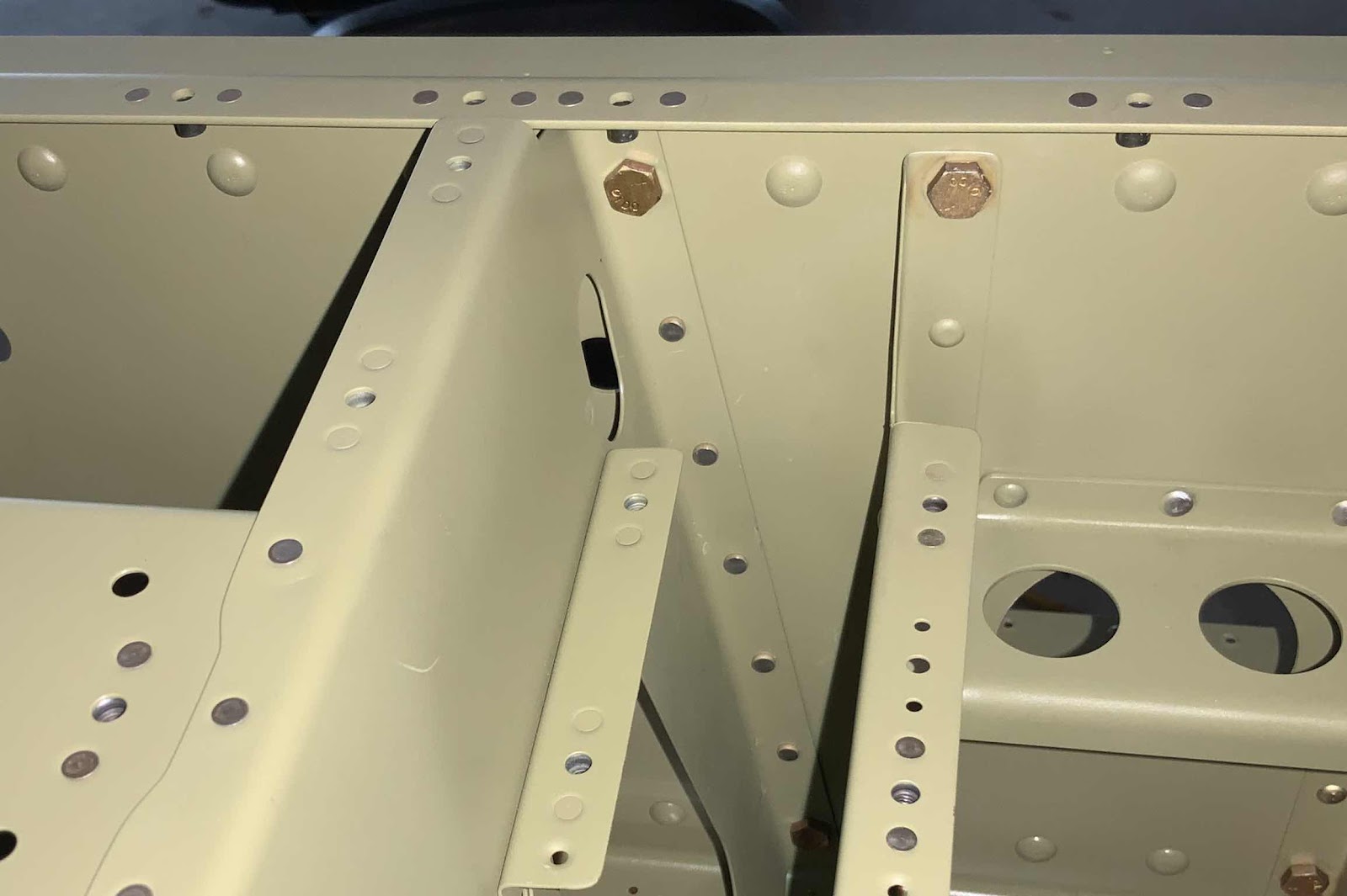
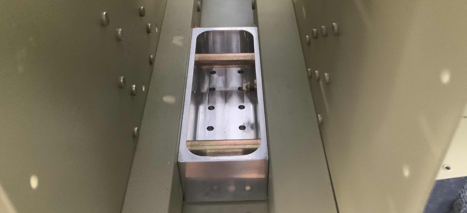
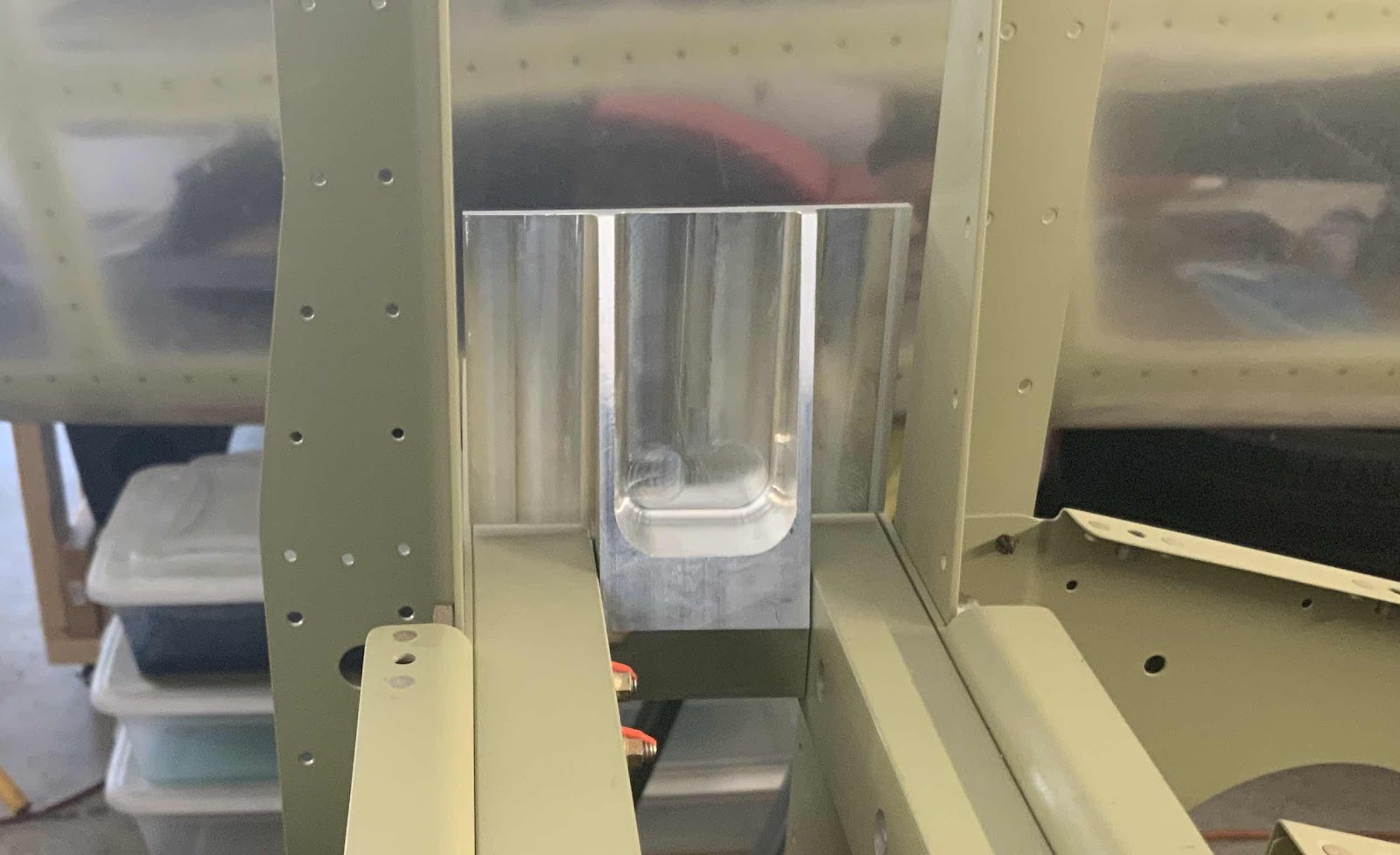
.....and this is the right side.  The plans call for the hardware to be installed as shown below.....so, I did.  However, I should have read JUST a little further in the plans prior to doing so.  NOTE:  Very shortly, these Lower Drag Fittings will get riveted with cherry rivets to the Center Bottom Skin and Forward Bottom Skins.  I want to prime the Fittings before they get installed.  So, now, I have to remove the hardware to prime the Fittings and then re-install the hardware.
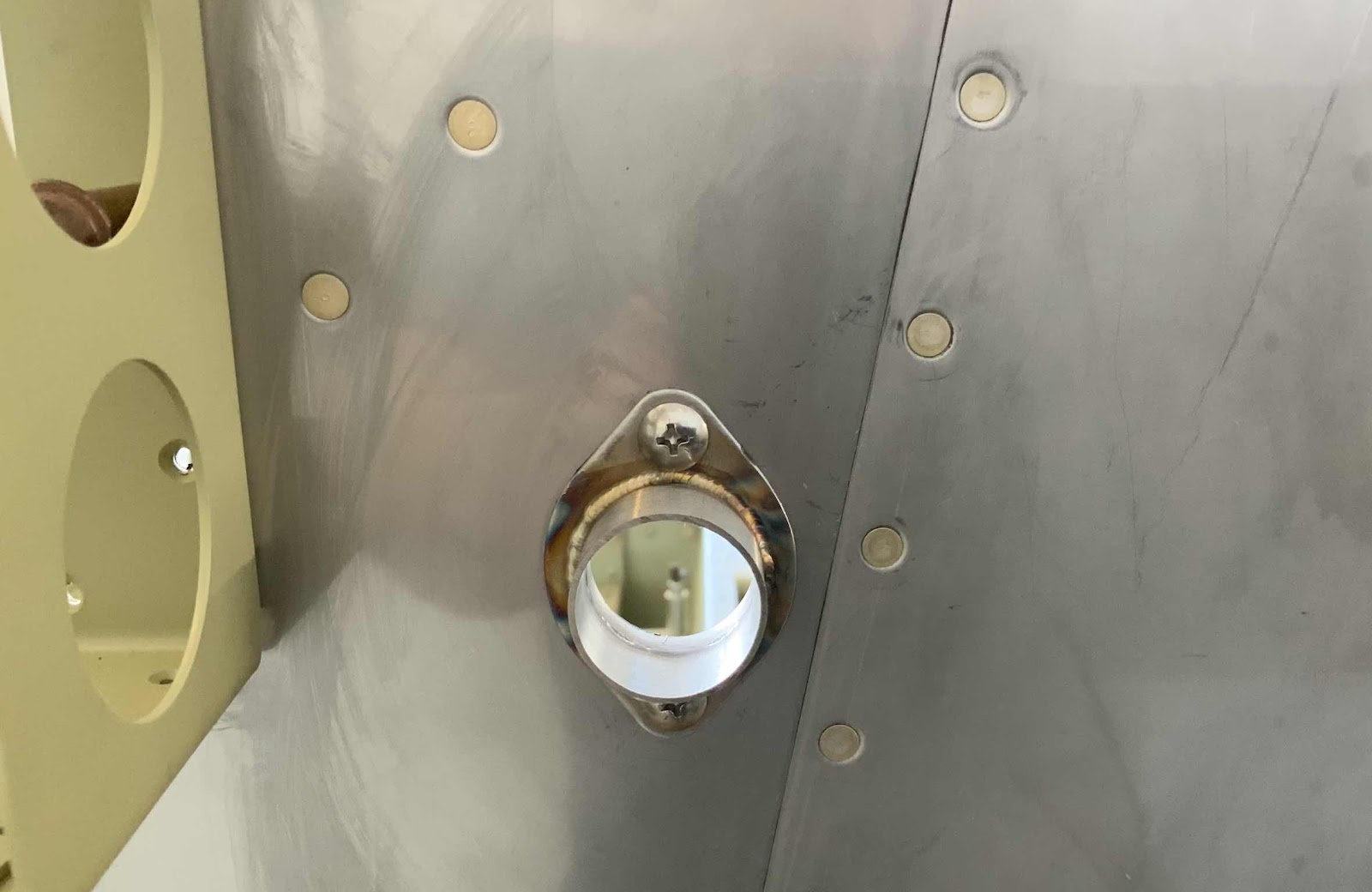
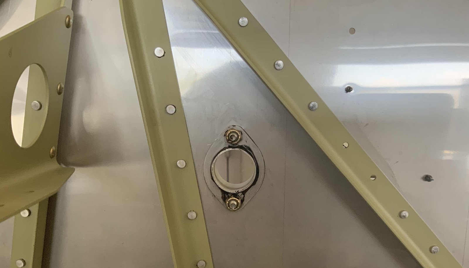
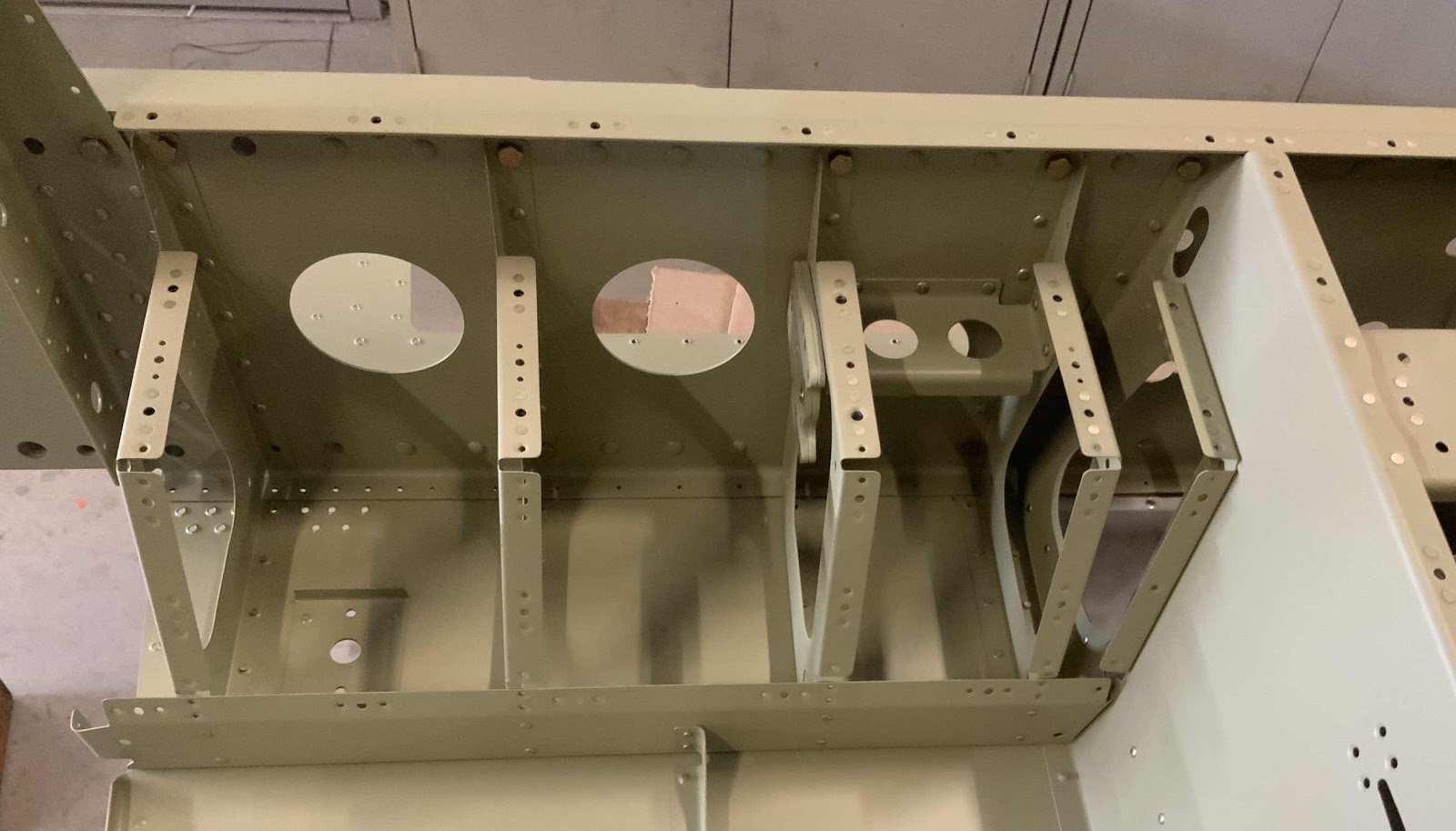
These are the F-01464-L and -R Upper Drag Fittings.  These will be installed in the “upper” area between the Forward Fuselage Lower Structure and Mid Fuselage Lower Structure.

This is the left side.....

.....and this is the right side.  More on these two pieces later in the post.
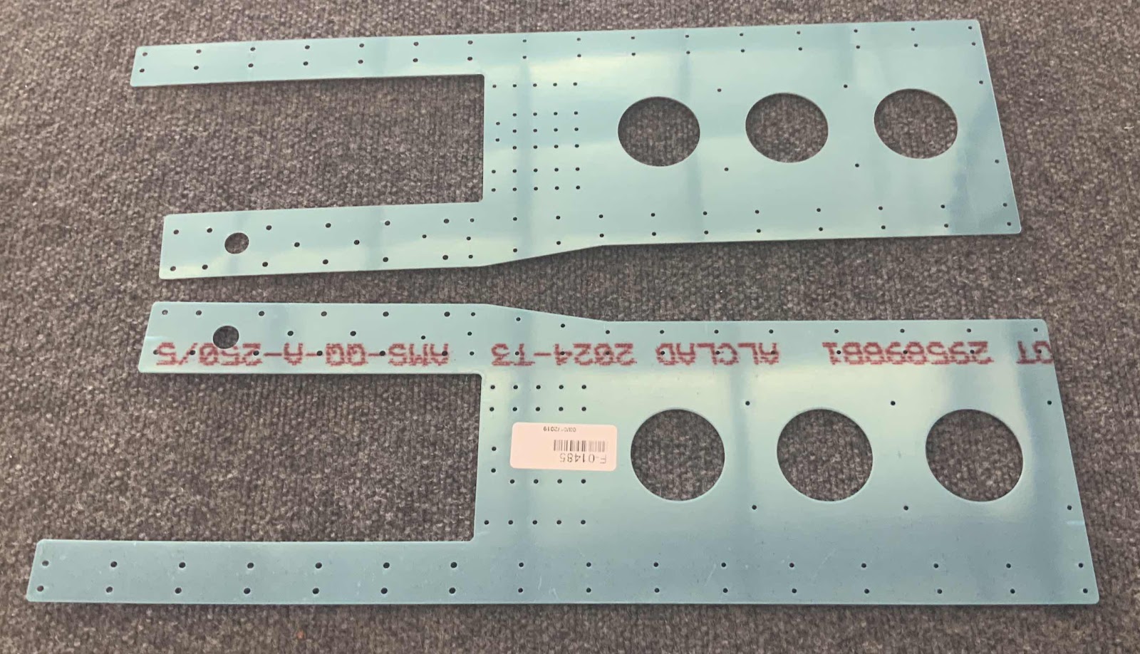
Shown here are the F-01485-L & -R Center Section Side Panels still in their sweet blue plastic.
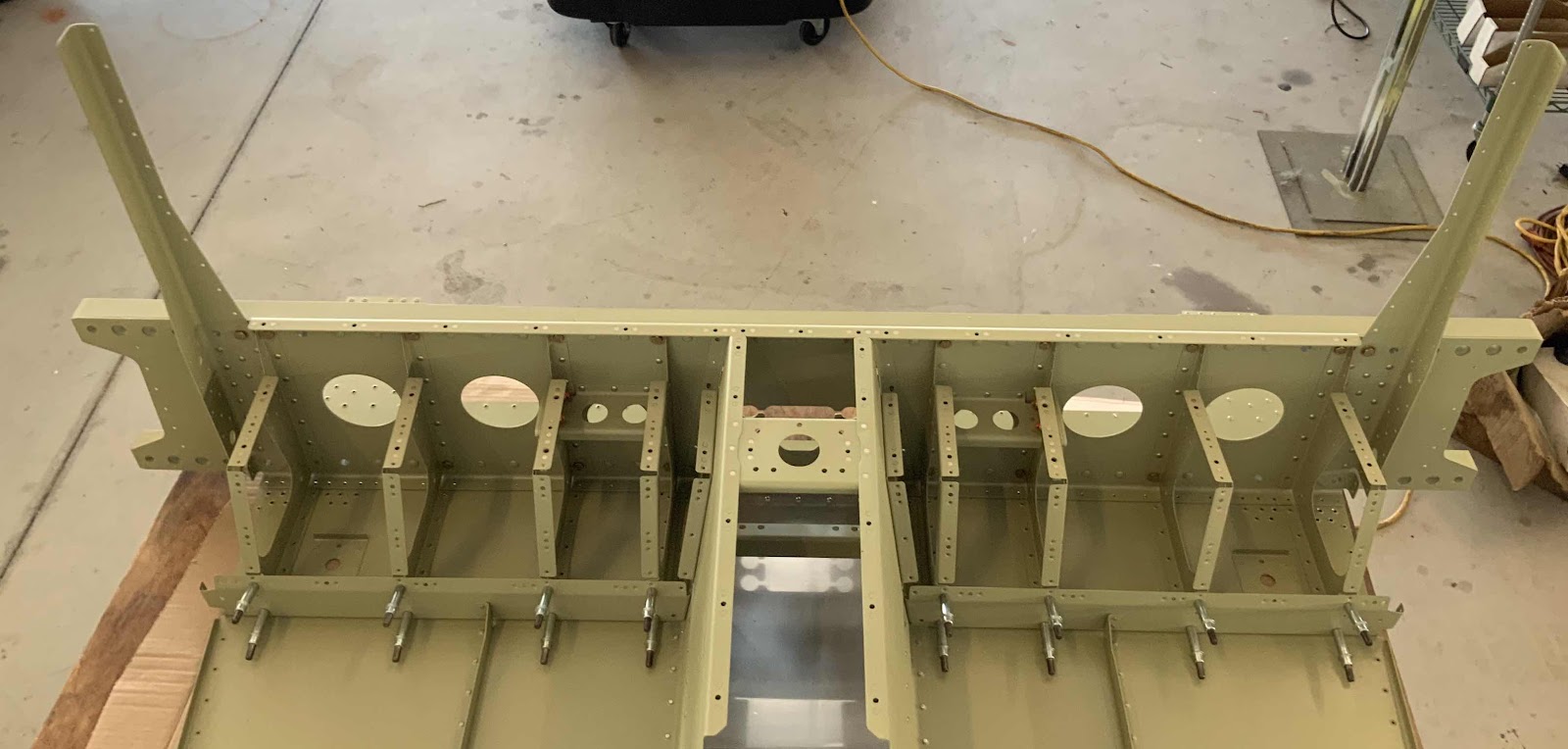
I removed the plastic and installed them to the Fuselage using as many clecos as possible (plans directed).  Here you can see both Side Plates clecoed to the  Fuselage.  The next step is to firmly clamp the Upper Drag Fittings to the Center Section Side Plates.  I used my blue squeeze clamps shown below.

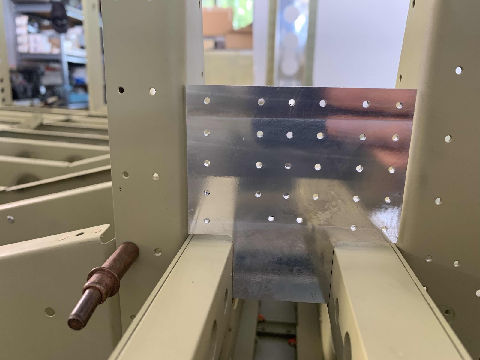
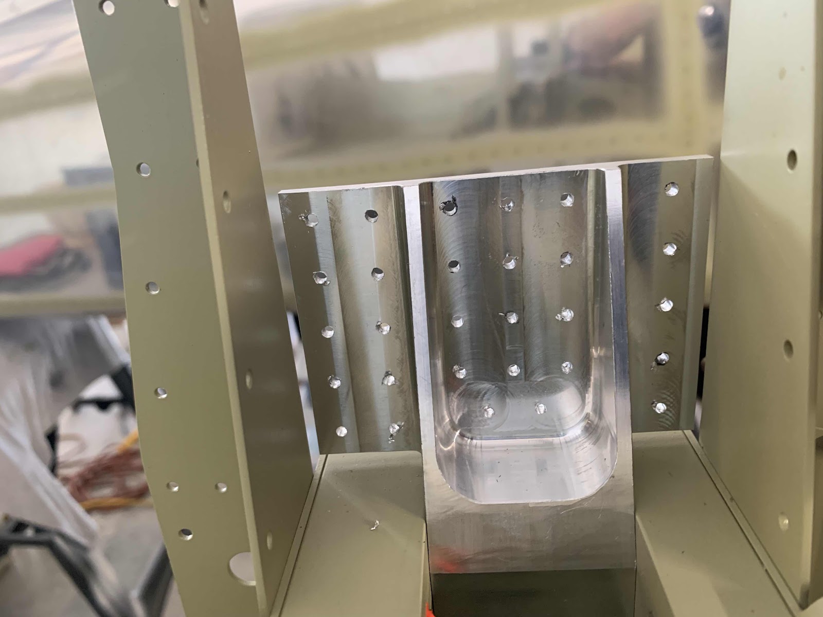
Once everything was clecoed and clamped together, it was time to match-drill #40 the holes in the Center Section Side Plates into the Upper Drag Fittings.  Each side has 29 holes that need to be match-drilled.  Shown here is the left side.  I used a 6” #40 bit to drill most of the holes, but I had to use a 12” bit on a few of them.

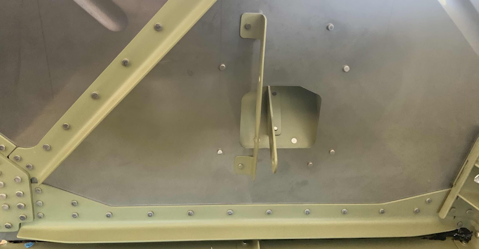
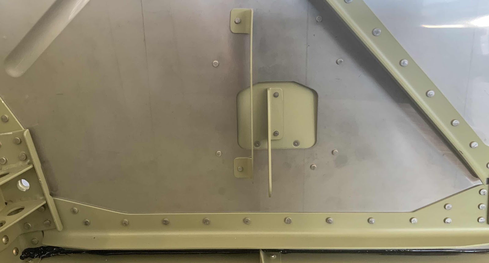
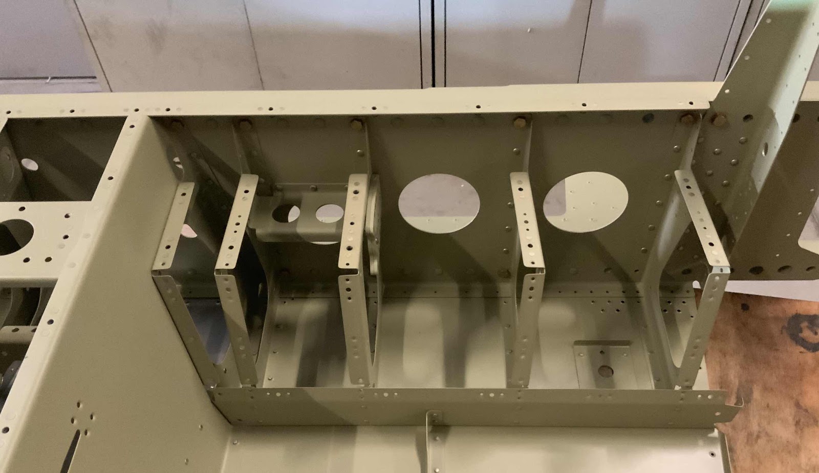
After all the match-drilling was complete I removed the Side Plates and here is what the Upper Fittings looked like.  This is the “outboard” side of the -R Fitting.....
.....and the “inboard” side.
I then removed both Upper Drag Fittings and both Lower Drag Fittings.  Finally, I deburred all the holes in the Upper Drag Fittings and Center Section Side Panels.  I’ll pick it up here tomorrow.

Saturday, September 7, 2019

Fuselage, FWD/MID Side Structure (Part 1)


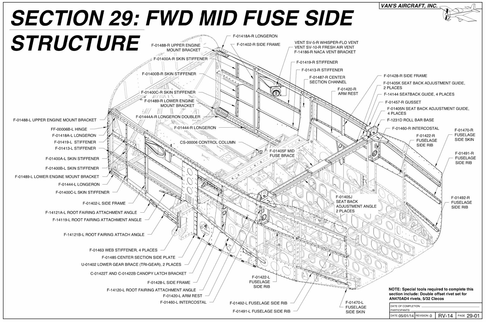
I finished up with Section 28 earlier today, so here goes Section 29.  The first step in this Section is to prime the Forward Bottom Skins and the Center Bottom Skins where they overlap.  (It is also recommended that all overlapping Skins in this Section be primed along any areas of contact).  I had previous primed both of these Skins, so step 1 is automatically completed.....off to a great start!
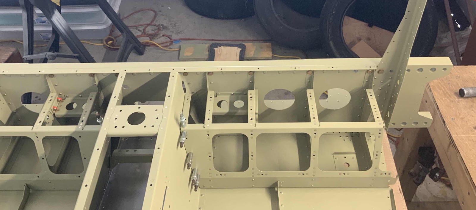
The next step is to join the Forward Fuselage Lower Structure with the Mid Fuselage Lower Structure by sliding the assemblies together on a workbench.  The two Structures together are becoming rather large, so I put both of my workbenches together to work on them.  Here are the two assemblies clecoed together and ready for the next step.

Fuselage, FWD Lower Structure (Part 15)


Thursday, September 5, 2019

Van’s Aircraft Factory Tour and RV-14 Demo Flight

Recently, work took me to the Pacific Northwest United States.....specifically, the state of Oregon.  So, you know what that means right????  I HAD TO GO VISIT THE MOTHERSHIP!  

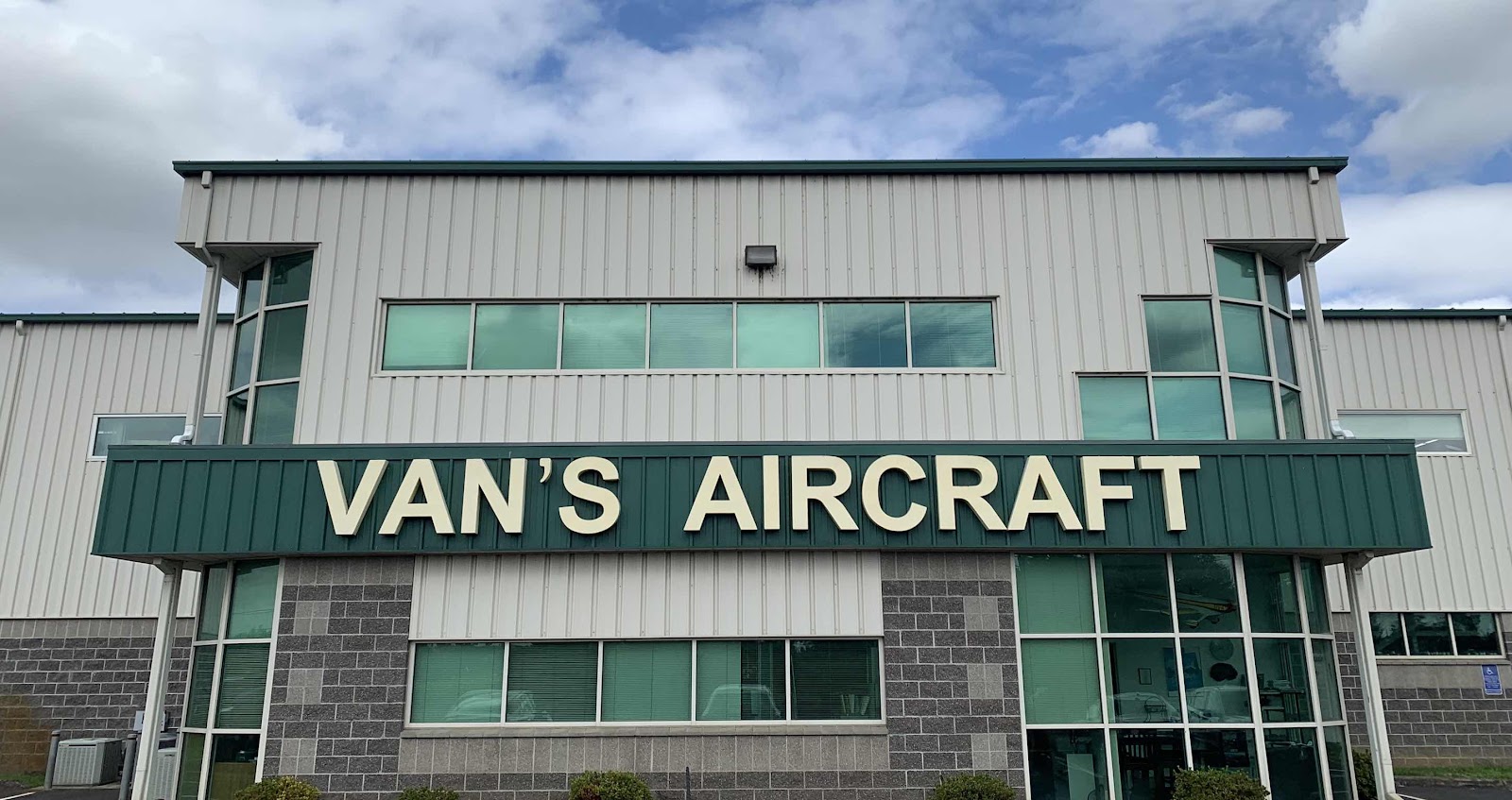
There it is....in the flesh (I guess in the metal)!!!!!

KUAO, Aurora State Airport, Aurora, Oregon


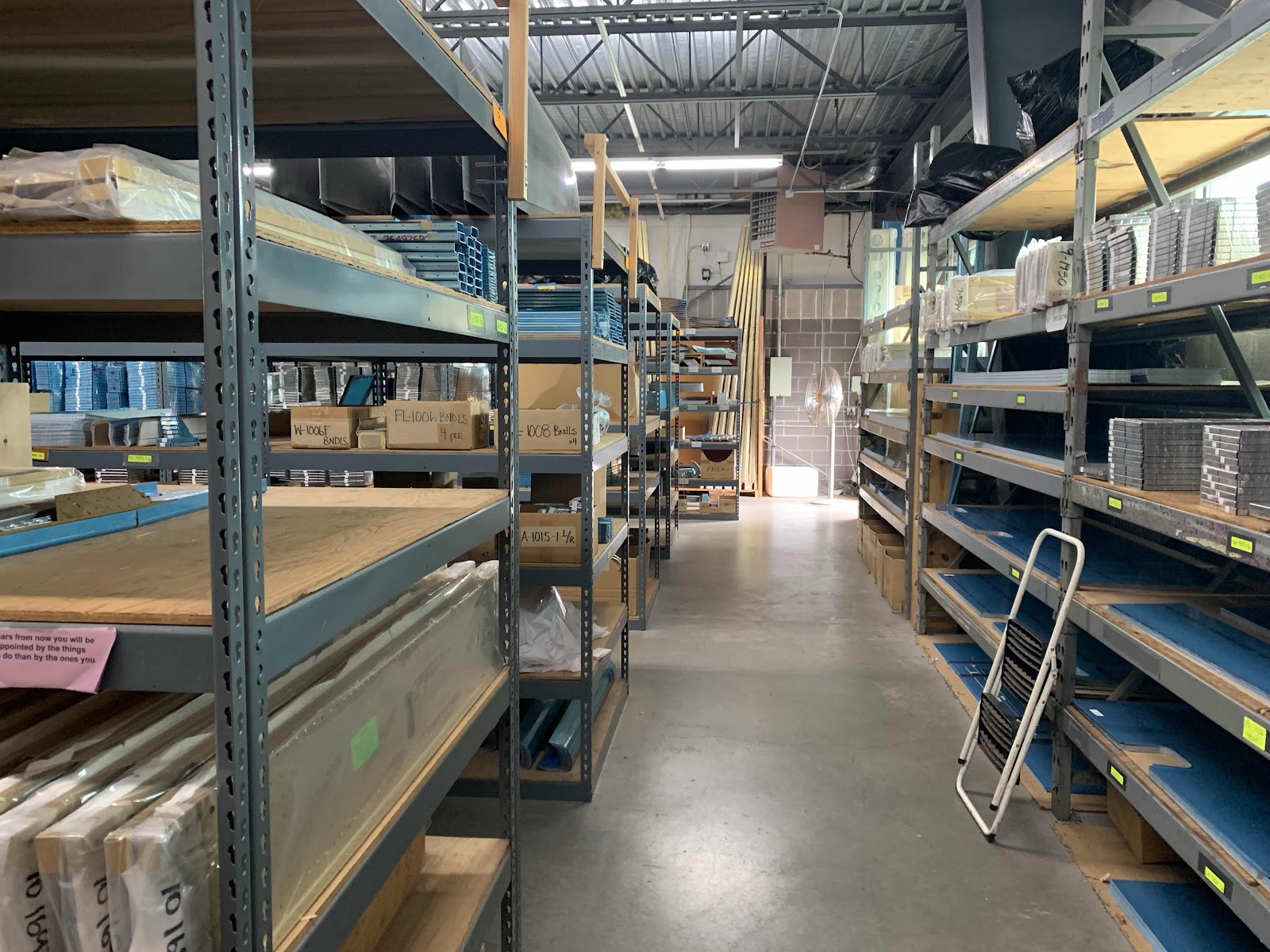
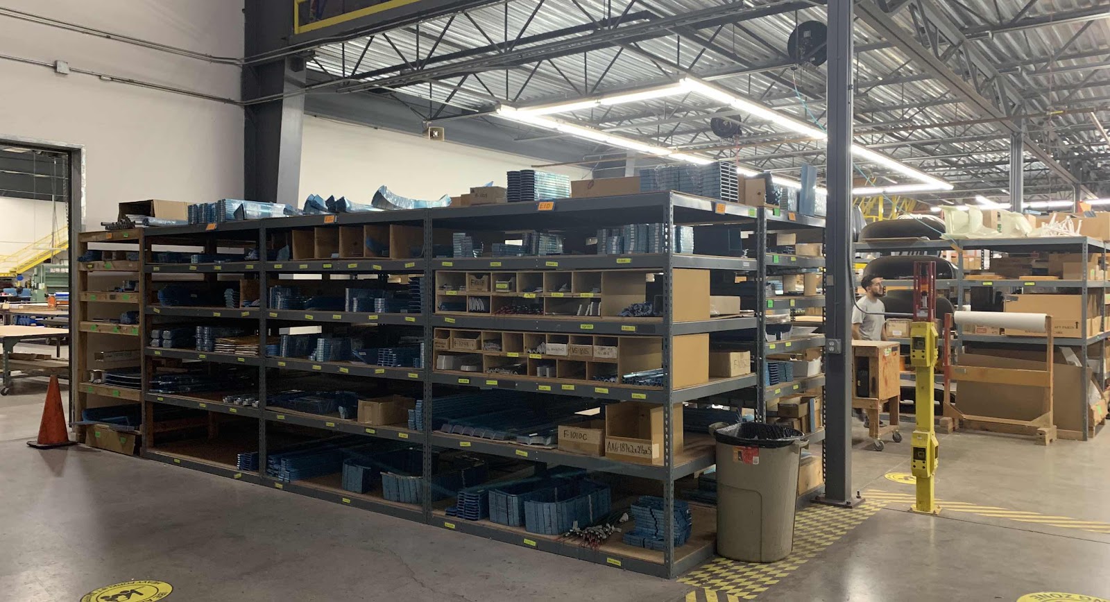
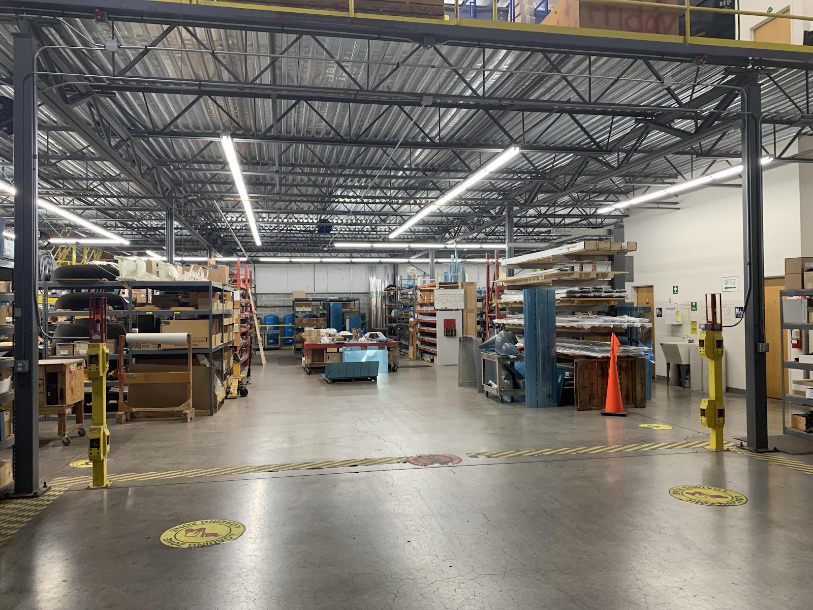
Van’s Aircraft gives factory tours twice a day at 0930 and 1330.  We went on a great tour at 1330 with Sterling.  The tour started with a walk through of their huge warehouse showing all the parts and pieces that Van’s keeps in stock.....Ribs, Spars, this part and that part.....

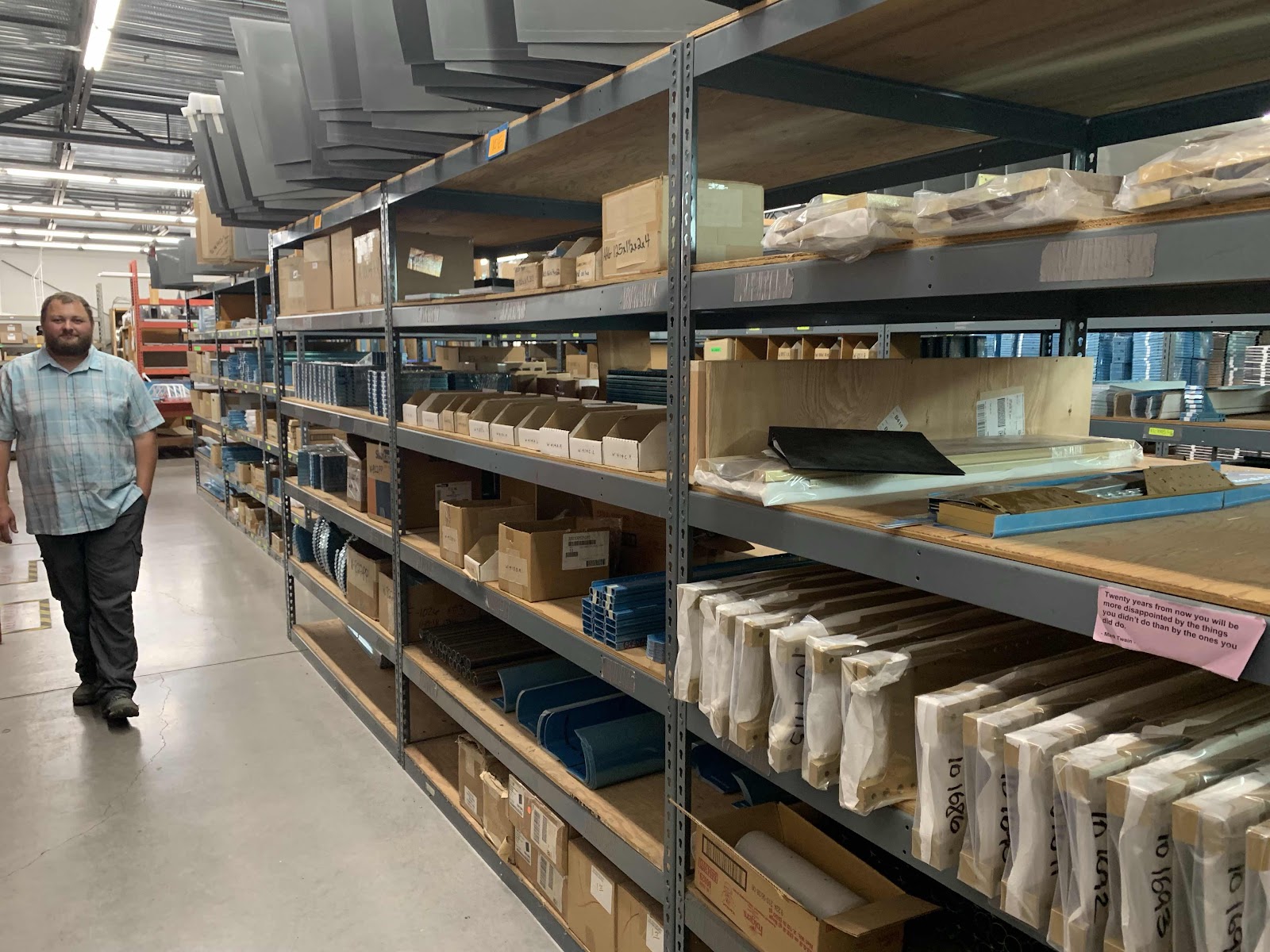
More parts.....fairings on the top shelf.

Even more parts.....


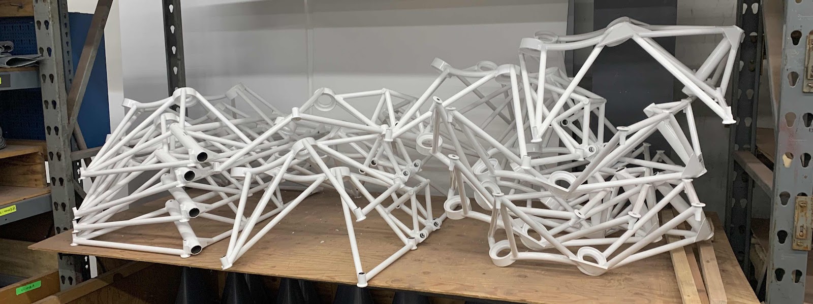
A whole mess of engine mounts.....

.....and gear legs.


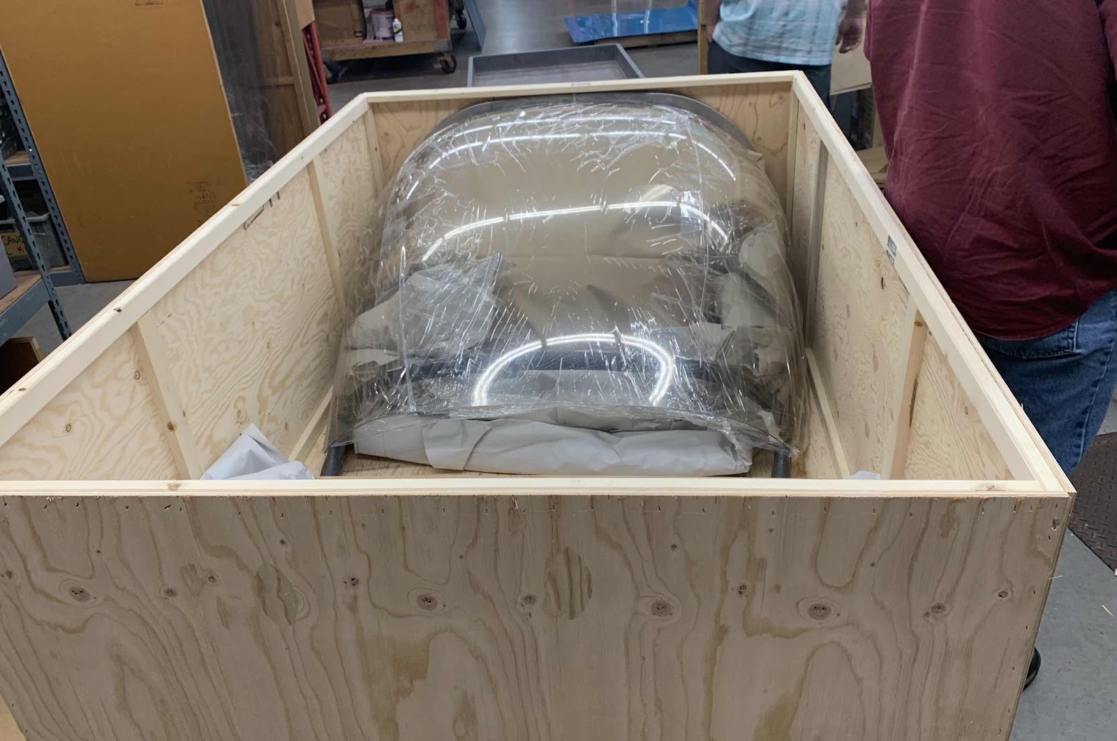
All of the crates that we all have received from Van’s get packed right here in this area.  You can see the empty crate on the floor about to get stuffed like a Christmas stocking for some lucky builder.

This is a finishing kit being packed for someone.  If I remember correctly, Sterling said this was an RV-7 finishing kit.  I have only one kit left to order for my RV-14.....looks like it will come in a very big box!

If anyone is interested in ordering a quick build kit, this is part of what you will get.  RV-10 fuselages on the far right, RV-14’s in the middle, and RV-8’s on the left.

This is another part of what you will get with the quickbuild kits.....these are RV-10 and RV-14 wings.  

This is where that sweet blue protective plastic we all love is applied to the aluminum.

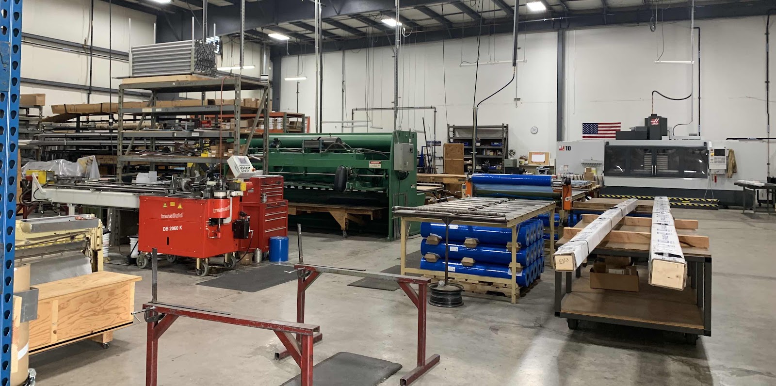
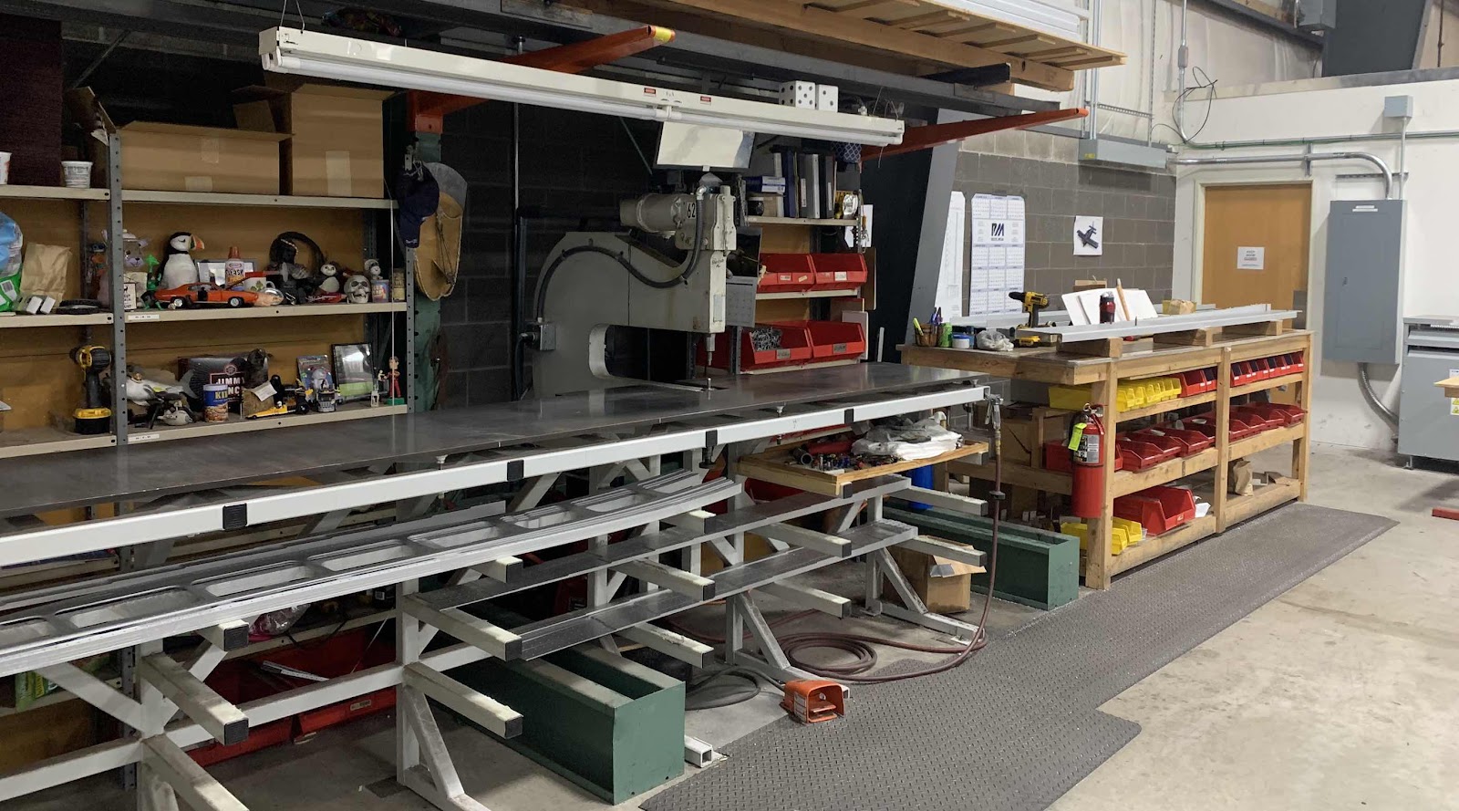
Sterling said Van’s continues to try and manufacture more and more parts in house.  From what I understand, this is their most recent effort to do that.  This is where the Spars for RV-14’s are made (not sure if the Spars for the other models are made here yet).  Look at the size of that C-frame used to smash those big rivets in the Spars.


The tour finished in a hangar full of RV’s.  I took a panorama photo of the hangar.....you can see an RV-8A (on the lift), RV-7A, RV-9A, RV-12, RV-10, and RV-14.

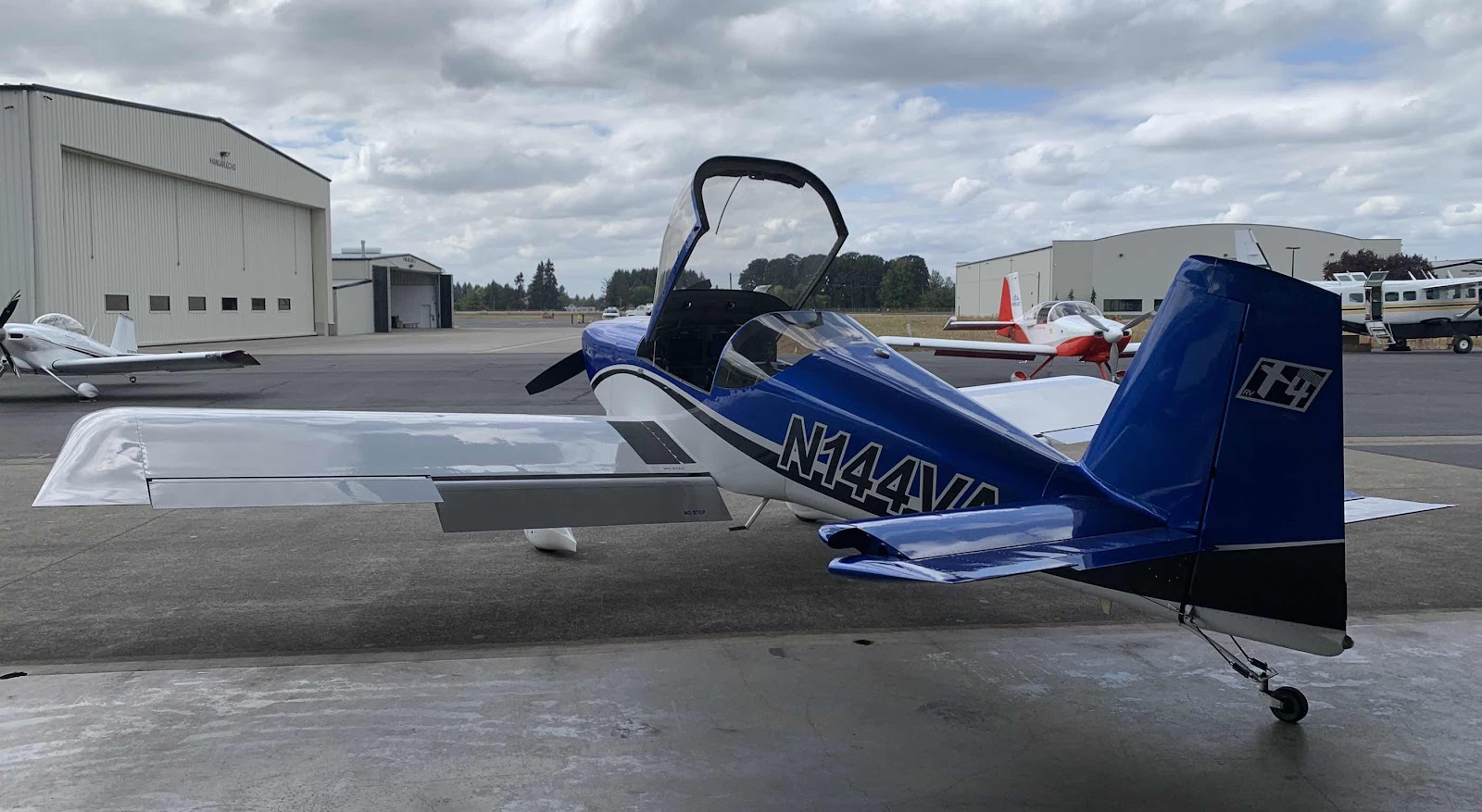
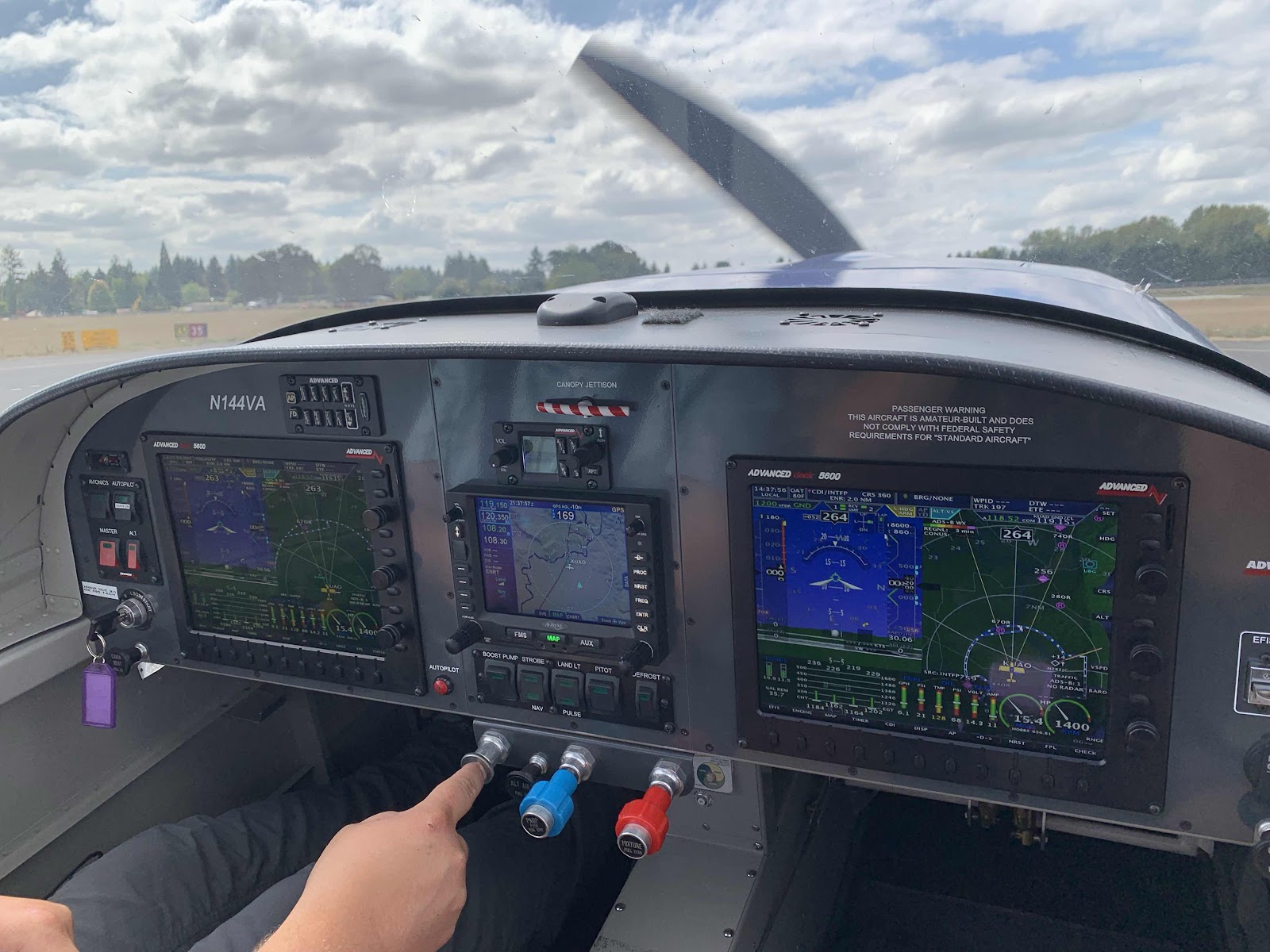
Here is the ultimate finish line....roughly a year to a year and a half away.  Guess what?  Even though I’ve already purchased kits from Van’s for my RV-14, they STILL gave me a ride in the company demonstrator....N144VA!


Start up for my demo ride


Taxing out for takeoff


Engine runup prior to takeoff


Takeoff


Landing


Taxing to park


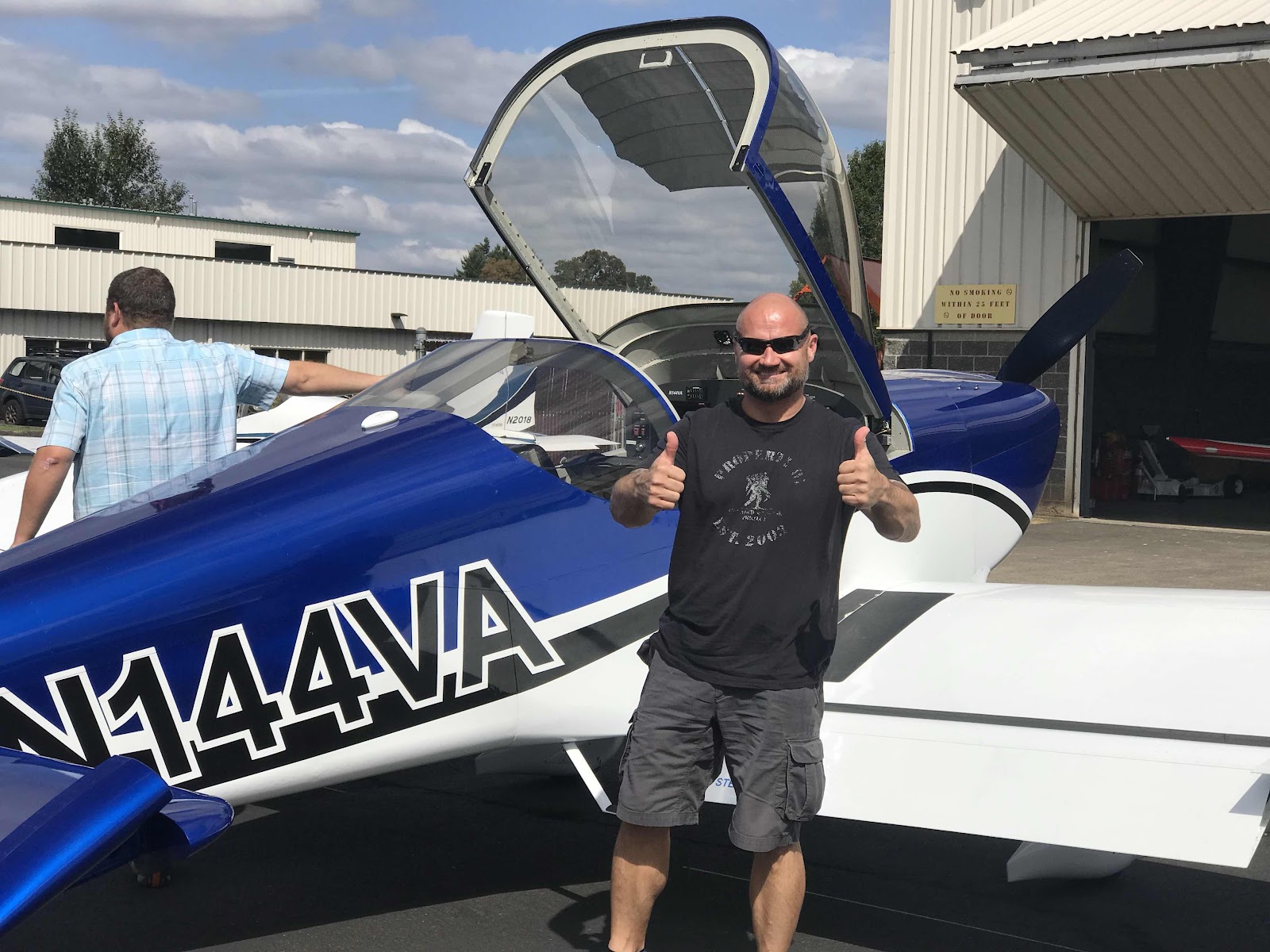
“The RV Grin”...I’m sold!!!!!  I guess I’ll buy one!!!!!


Fuselage, FWD Lower Structure (Part 13)