Sunday, January 28, 2024

RV-14 Tailwheel Assembly - JD Air

In June of 2021, I purchased and installed the RV-14 Tailwheel Assembly including Steering Link from JD Air. The work and pictures in this post are from June 14, 2021.

Here are the instructions I used for the installation that are published on their website.

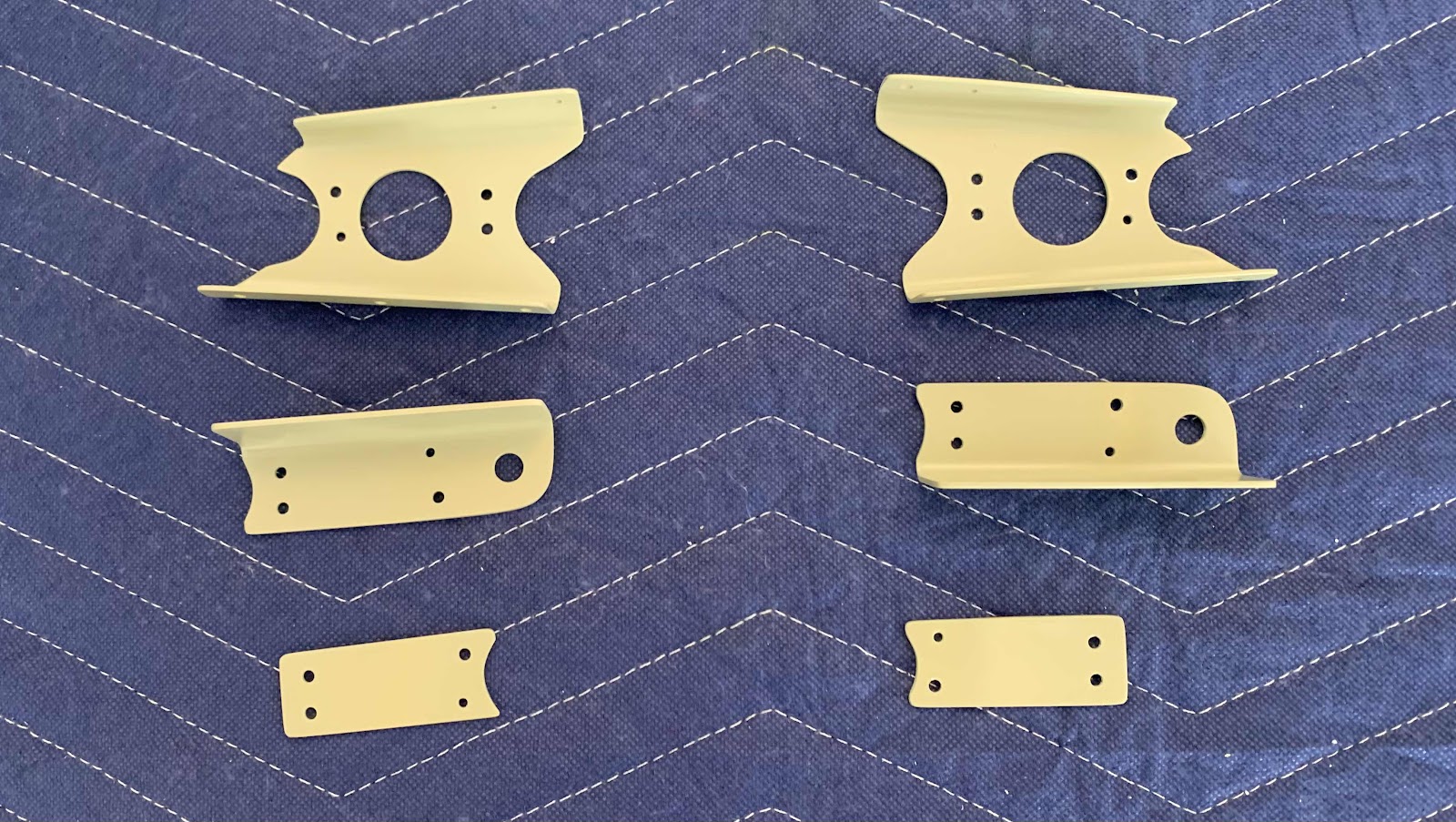
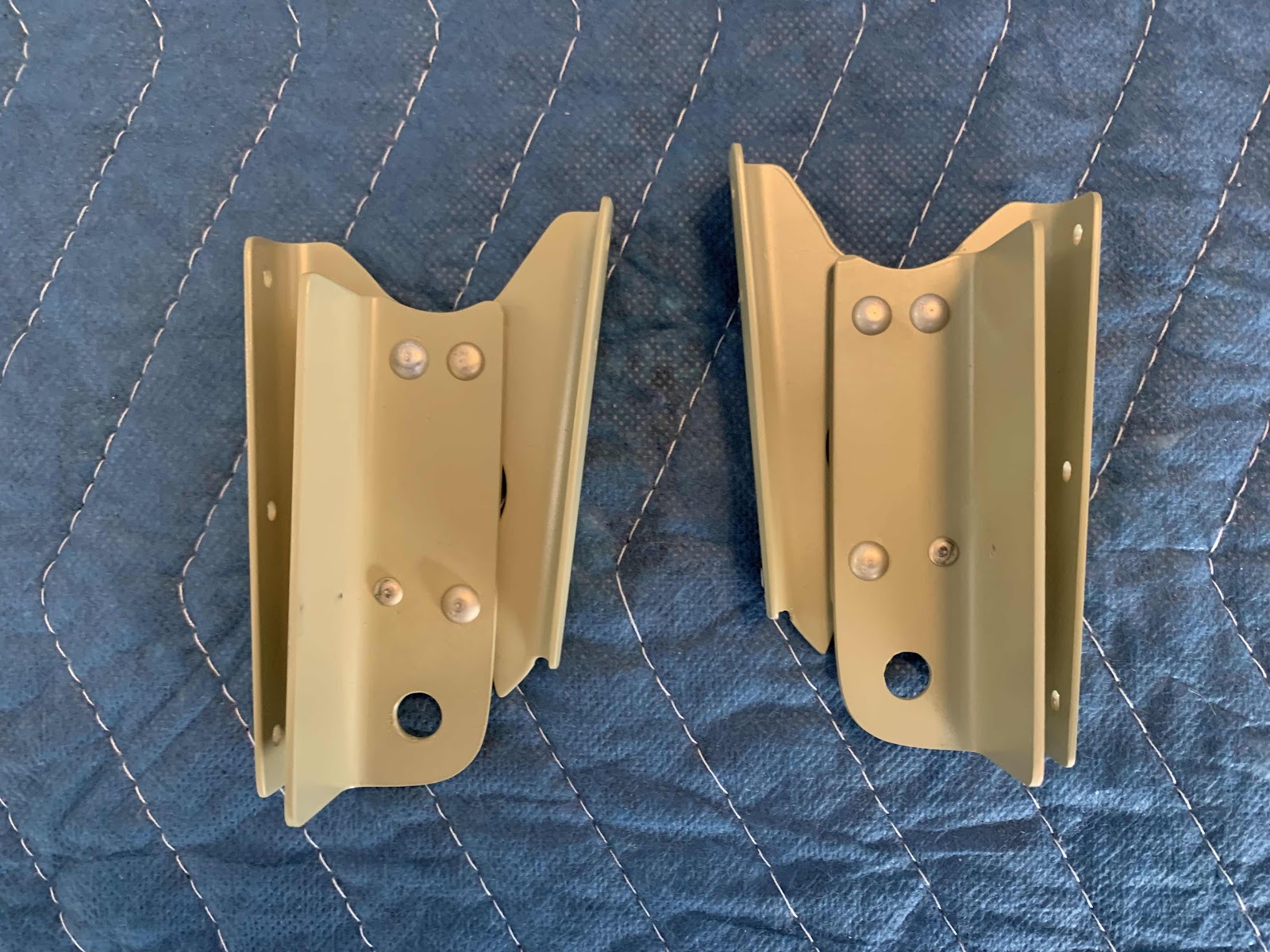
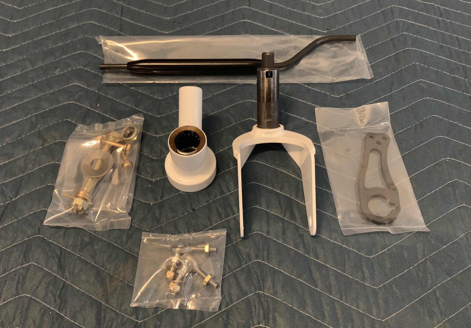
These are the parts and hardware that comes with the kit.  I decided not to use the Light Weight Tire (available option) and used the stock U Tail Wheel 6” from Van’s.  I flew an RV-7 for a couple of years that had one of the Light Weight Tires and I wasn’t a big fan of it.  It gave the plane a noticeably rough ride while taxiing that wasn’t very comfortable…..in my opinion.  I know other RV owners that love them, so to each his own.

The first step is to install the Dual Bearing Yoke onto the U-00016 Tail Gear Spring with (2) AN3-12A bolts, (2) AN960-10 washers and (2) AN365-1032A nuts.  This is the same way the Van’s stock Yoke is installed, but they just use different hardware. 


Now, the Tail Wheel Fork is installed through the Yoke, the Adjustable Single Control Arm, the Custom 1/2” Belleville washer and a AN364-820A nut holds everything together.


Next, the stock Van’s U Tail Wheel 6” (my preference over the Light Weight Tire) is installed on the Fork using an AN6-31 Bolt, (2) AN960-616(L) washers, (1) AN960-616 washer, an AN310-6 castle nut and (1) MS24665-238 cotter pin.


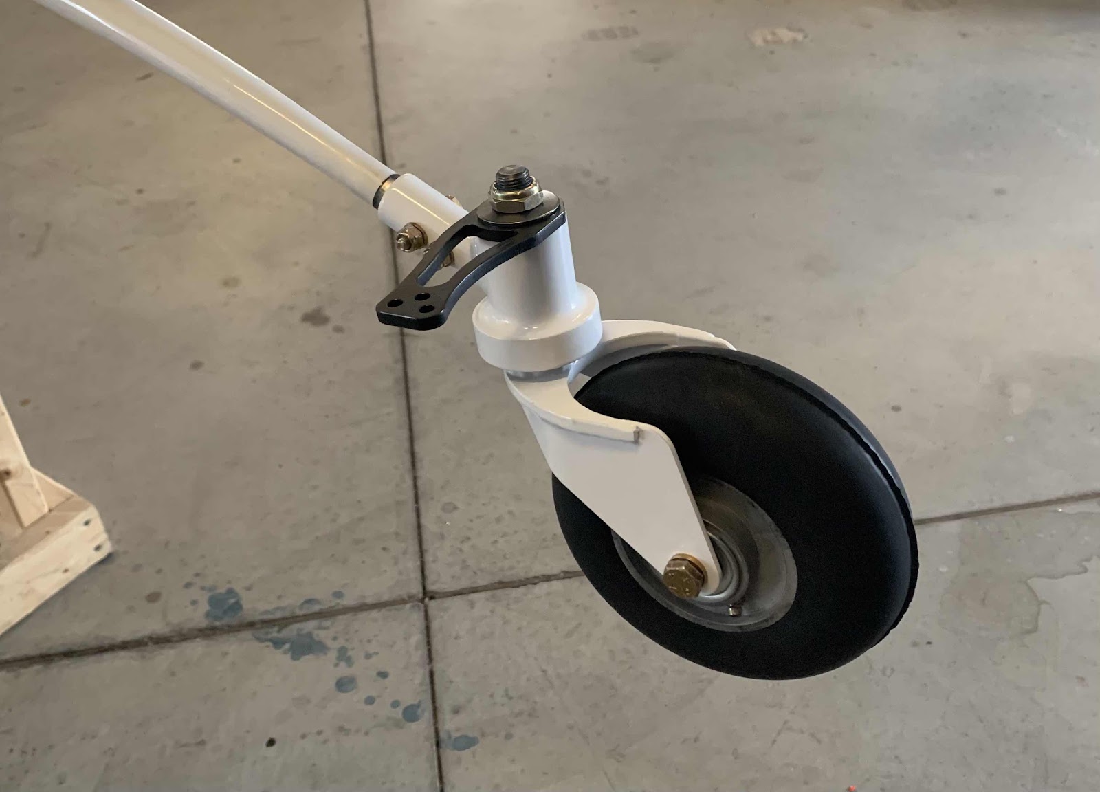
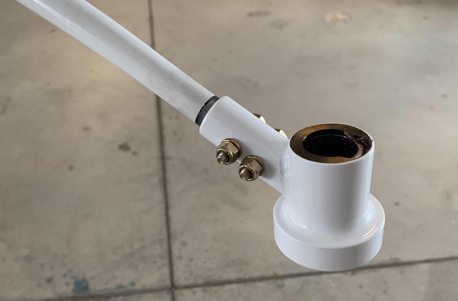
Finally, the Tail Link is installed following these instructions on their website.  These two pictures show the entire assembly completely installed.


Rudder Pedal Extensions - JD Air

In March of 2020, I purchased and installed the Rudder Pedal Extensions from JD Air.  The installation of this hose kit was completed in:

Fuselage, Section 33 - Rudder and Brake System, Part 9 (also included below)

Here are the installation instructions published on their website.

Gear Leg Brake Hose Kit - Aircraft Specialty

In June 2021, I purchased and installed the Gear Leg Hose Kit from Aircraft Specialty. The installation of this hose kit was completed in:

Fuselage, Section 40B - TD Gear/Engine Mount, Part 6 (also included below)

Here are the installation instructions published on their website.

Cabin Brake Hose Kit - Aircraft Specialty

In March of 2020, we purchased and installed the Cabin Brake Hose Kit from Aircraft Specialty.  The installation of this hose kit was completed in:

Fuselage, Section 33 - Rudder & Brake System, Parts 10 - 13 (also included below)

Here are the installation instructions published on their website.

Cabin Fuel Lines - Aircraft Specialty

In March of 2020, I purchased and installed the Cabin Fuel Line Package (also known as the Complete Firewall Aft Hose Kit) from Aircraft Specialty.  The installation of this hose kit was completed in:

Fuselage, Section 31-Fuel System, Part 4 - 6 (also included below)

Here are the installation instructions published on their website.

RV Max Flap Actuator - PH Aviation Services (Part 3)

The work and pictures from this post are from November 12, 2022.

Finally, here is the completely installed RV Max Flap Actuator.  Upper portion of the Actuator is attached to the modified Flap Motor Brackets with the following hardware:

(1) AN5-13 bolt
(2) NAS1149F0563P washers (AN960-516)
(4) NAS1149F0532P washers (AN960-516L)
(1) AN310-5 Castle Nut
(1) MS24665-134 Cotter Pin

The bottom portion of the Actuator is attached to the WD-1013A Flap Crank using the stock hardware called out in the build plans page 34-05.  This includes:

(1) AN4-12A Bolt
(2) Bushing-AL .259x.375x.168
(1) NAS1149F0463P
(1) MS21042-4


The upgraded PH Aviation Services RV Max Flap Actuator is now completely installed.  The only remaining step is to make the electrical connections.  I will do that later when I start making the electrical connections for the entire plane.

RV Max Flap Actuator - PH Aviation Services (Part 2)

The work and pictures from this post are from November 11, 2022.

As the previous post mentioned, there are some modifications that need to be made to the stock parts in order for the RV Max Flap Actuator to work properly.  

The PH Aviation website publishes installation instructions titled Installation of PH Aviation Flap Actuator in RV-14.  These are the instructions that I followed for these modifications and installation.

The first page of the instructions says the F-01466-L & -R Flap Motor Brackets will need to be modified and that this should be done PRIOR to installing them as instructed in the build plans on page 32-07.  Since I found out about the Actuator after I completed Section 32, I will have to remove the previously installed Flap Motor Brackets.  As a result, I also decided to order two new Flap Motor Brackets from Van’s…..I just wanted new stuff since I had to drill out all the rivets in the original Brackets.

Now, the picture below shows the progress of the modifications starting at step #19 of the instructions.  I didn’t feel the need to post all of the same fabrication pictures that are included in the instructions in step #1 through steps #18.  The top two pieces are the modified stock Flap Motor Brackets from Van’s (the new ones I ordered).  The middle two pieces are the 1” x 1” x 0.063” aluminum angles after being fabricated.  The last two pictures are the 0.063” Shims after being fabricated.

The Angles and Shims for each “side” were clecoed and riveted to the modified F-01466-L & -R Flap Motor Brackets using (3) AN470AD4-5 and (1) AN470AD3-5 rivets.

Next, the modified Flap Motor Brackets are riveted to the front to the F-01405F Mid Fuse Brace using (2) AN470AD4-4 and (2) AN426AD3-4 rivets.


The back of the modified Flap Motor Brackets are riveted to the F-01405G Flap Motor Channel using six CR3213-4-2 CherryMax rivets (two of the rivets are hidden behind the C-01438 Canopy Latch Torque Tube).  The bottom two holes were used with the old, longer Brackets and will be left open for the new, shorter Brackets.  You can see a little scraped paint on the Torque Tube from removing the previous rivets in the old Brackets…..

…..so, obviously, I had to clean that up and re-paint those areas.  This is why I like using the SEM paint products…..look how nicely the new paint blends with the old paint.


I also cleaned up the re-painted the areas the front side.

And that finishes the modifications to the plane for the new RV Max Flap Actuator.  Here are a couple pictures showing the completed install.


I will install the Actuator during the next work session.

Friday, January 26, 2024

RV Max Flap Actuator - PH Aviation Services (Part 1)

Previously, I completed Section 34 (Flap Actuation System).  In completing that section, I installed the stock Van’s ES 85615-10 Linear Actuator (Flap Motor) as directed in the plans.  Here is what the Flap Motor looked like before I installed it in the plane.


Now, fast forward to Section 54 (Flap Position Sensor) of the build plans.  This section has you install The Ray Allen Company ES MSTS POS-12 Flap Position Sensor.   As the only Post for Section 54 says, I wasn’t the biggest fan of that setup.  (See Section 54).  Like I said, there is nothing wrong with the factory setup, I just wanted something more “all in one” and more robust.

As I also mentioned in Section 54, I began to do some research to see what options existed in the aviation market.  Based on my research, and a recommendation from Aerotronics, I decided on the RV Max Flap Actuator from PH Aviation Services in March of 2022.  This Actuator has internal limits, internal position sensing and is very robust.  This setup does away with the two piece setup (separate flap motor and position sensor), did away with the safety wire that was required to be installed on the factory actuator and combined everything into one robust setup.  That pretty much meet the requirements I was looking for in a replacement flap motor.  I didn’t get any pictures of the actuator prior to installing it, so if you click on the link I provided above, it takes you right to the page.  On that page, it gives you the specs and price for the actuator.

As the PH Aviation Services website says, this is not a drop in replacement for the stock actuator.  So, some minor modifying was required, but was pretty easy to do.  I will use this section to show you the modifications and what it looks like installed.

Thursday, January 25, 2024

Panel Installation (Part 2)

Just to give some perspective on the whole instrument panel process:

For timeframe purposes:  
Initial Panel Design Started:  April 20, 2021 (See “Initial Panel Design” tab)
Panel Build Started:  January 12, 2022 (See “Panel Build” tab)
Completed Panel Delivered:  June 9, 2022 (See Panel Installation, Part #1)

These are two pictures I took on April 9, 2020, of the F-01467 Instrument Panel Frame (front and back) after it was Akzo primed and the 23 K1000-06 nutplates were riveted into place.


The two pictures below were taken April 10, 2020, after the Instrument Panel Frame was painted with SEM Medium Gray (same color as most of the interior).


And these two pictures were taken on January 23, 2021.  To complete the Instrument Panel Frame assembly and installation, an additional 12 K1000-06 nutplates were installed between the Frame, the Instrument Panel Attach Brackets and the Instrument Panel Standoffs.  That completed the Instrument Panel Frame installation and it’s now ready to accept the panel.  This picture was taken from the pilot side…..

…..and this one from the copilot/passenger side.


NOW, on June 26, 2022, the completed instrument panel was attached to the Instrument Panel Frame for the first time!!!!!  Aerotronics supplied the screws used to attach the panel to the Panel Frame (into all those nutplates).  They even went as far as painting the countersunk screw heads the same color as the panel (and provided a bag of extras).  To say I am happy with the panel is an understatement…..it came out perfect as far as I’m concerned.


Panel Installation (Part 1)

The finished panel from Aerotronics was delivered by ABF Freight on June 9, 2022.  I don’t have any “box opening” pictures, but the panel was packed into the box very, very well and resulted in no damage to the panel.  Now, lets get it into the plane!!!!!


Panel Build (Part 11)

Here is the COMPLETED panel!!  We love it!!


I will create a section in the blog for the panel installation.

*****This picture above is from Jason at Aerotronics on May 12, 2022*****

Wednesday, January 24, 2024

Panel Build (Part 10)

My panel is 99.9%!  The analog HOBBS meter on the right side of the panel is the last item Jason needs to mount (that I know of).  The G3X has a HOBBS meter function, but I decided I wanted an analog one mounted on the panel.  I would say you could call me old school, but that is the only thing on the panel that could be considered old school….so, that won’t work!  Additionally, the two open holes on either side of the dimmer switches will be for the seat heater (pilot and copilot) switches.  I will install those in the future when I install the seats and interior.  

I think the panel looks AMAZING!  With the unbelievable capabilities of ForeFlight, I will use my IPad to complete the panel.  ForeFlight and the GTN 750Xi will be able to communicate with each other for traffic, weather, flight plans, etc. This will be an awesome combination of capabilities.


Here is a picture behind what will be the sub panel…..

…..and behind the G3X PFD.

This picture shows the remote mounted transponder and comm radio and their associated plugs.  Jason just set them here for the picture (and to make everything work), as this is not where they will be mounted in the plane.  I have fabricated a bracket system to mount them behind the sub panel on the right side utilizing the “glove box” cutout in the sub panel.  I’ll do a section showing how I fabricated and mounted that bracket and avionics.

*****The pictures above are from Jason at Aerotronics on May 6, 2022*****

Panel Build (Part 9)

The panel for the RV-14, as designed by Van’s, calls for a modular panel (pilot side, center stack, copilot side).  I took this picture from inside N144VA, Van’s RV-14 demonstrator, when I got a ride following the factory tour in August 2019 (linked at the top right of the blog).  You can easily see the “separation” of each modular section.  There is absolutely nothing wrong with this setup and lots of people use this……not just in RV’s.

However, I wanted a “single panel” design without the “modular lines”.  I feel like it’s a cleaner and more finished look…..just my preference.  So, after a fair amount of back and forth with Aerotronics on what I wanted exactly, here is the end result and the finished panel the designed for me.  All of the panel labeling is etched and paint filled.  The tail number will be added later with some sort of white color matched sticker.  I’m going to see if my wife can come up with something better.  For the panel color:  Andre from Aerotronics contacted Classic Aero Design and got the paint codes that will match this color in our interior.  (The interior from Classic Aero Design will be captured in a separate section of the blog).


*****The picture above is from Jason at Aerotronics on April 27, 2022*****

Panel Build (Part 8)

The following picture was sent to me on March 9, 2022.  

Getting close to the end!!!!!  Almost there!!!!!  Jason just needs to wire the circuit breaker panel (mostly the bundle of red wires on the bottom left).  These wires will go into a plug that can be detached from the circuit breaker panel itself.  The last thing to do is cut off the zip ties and replace them with avionics string (which will be done when the painting and etching is completed on the final panel).

After the circuit breaker panel is wired….she has power!


Demo mode on the G3X PFD.


*****Pictures are from Jason at Aerotronics*****

Panel Build (Part 7)

Here are some updated build pictures from March 4, 2022.

Jason says the panel itself still needs molex connectors for the canopy and CO detector, but the wires are already run for those.  He has separated the wires that will run to the left common fuselage harness, the right common fuselage harness and the power wires that will run to the circuit breaker panel.


*****Pictures from Jason at Aerotronics*****

Panel Build (Part 6)

These two photos are from March 2, 2022.

More progress on the panel!  If this is how much wire that is going into my panel, just one panel…..can you imagine how much wire they have in stock at the shop???  Jason believes this is about the bulk of the wires that will go into my panel.  He’s guessing, but maybe less than 10 more wires to be complete everything.

The fascinating thing to me is that every wire has a purpose…..remove one of the wires and something does work properly!  Amazing!!!!

*****Pictures from Jason at Aerotronics*****

Panel Build (Part 5)

These two pictures are from February 23, 2022.  The first one shows the G5 and associated switches in/around it (backup battery power, magneto switches, test switch, push to start).

This pictures just shows the back of the panel and amount of wires that are starting to show up…..

*****Pictures from Jason at Aerotronics*****