This blog was created to memorialize the building process of my Van's Aircraft RV-14 and to satisfy the requirements for certification in the Experimental Amateur Built Aircraft category. It will also serve as a central location for ME to reference in the future on processes and techniques I used during the build. Additionally, it will allow my family, friends, and other interested builders the opportunity to follow along during my build…..and might be helpful to someone along the way.
Yesterday, Jeff helped me finish riveting Wing Ribs #4 - #11. Since there were two of us, those rivets turned out quit well. The day prior, however, I shot the rivets by myself for Ribs #12, #13, and #1 - #3. I wasn’t completely happy with a few of them, so I spent about 30 minutes today removing the “bad ones” and installing “new ones”. Jeff helped me re-shoot them and the results were much better. I’m happy now.....
So, moving on.....
Not a lot of work on the Rear Spar, but I completed the Alumiprep and Alodine process on the three Rear Spar Doublers (right side of the picture), Rear Spar Reinforcement Form and Rear Spar Doubler Plate. They are now ready for Akzo primer during the next session.
My buddy Jeff had a few minutes to help me out tonight, so we were able to finish riveting the remaining Wing Ribs. We riveted Wing Ribs #4 - #11 to the Right Wing Main Spar using AN470AD4-7 universal rivets. We used a 3X rivet gun and tungsten bucking bar to complete the rivet installation.
This is the forward side of the Right Main Spar looking from inboard to outboard. You can see the vertical rows of shop heads of the installed rivets.
The is the opposite end of the Right Main Spar looking outboard to inboard. You can also see the vertical rows of shop heads.
Finally, this is a small section of the Right Main Spar between Wing Ribs #9 and #10. From this view, you can see the 10 manufactured heads of the installed rivets (5 on each Wing Rib).
After riveting all the Wing Ribs (except #14, as directed by the plans), I finished the prep work on the Right Rear Spar. I deburred the holes previously drilled for the Spar Doublers and cleaned all the edges. The next step is to dimple the upper and lower Flanges of the Right Rear Spar. Then, the Rear Spar and associated parts can be Alodined and Akzo primed.
Now that the Wing Ribs are clecoed back into place on the Right Main Spar, it was time to install the bolts/washers/nuts and rivets. Below is the excerpt from the plans regarding the installation of the bolts. NOTE: the picture below is for the LEFT WING. The Right Wing bolts/washers/nuts are installed in the same way and orientation. For my own tracking purposes, I highlight the bolts as they were installed to insure the proper size/length and orientation. My buddy Doc helped me install and torque all the bolts. These bolts, just like on the Left Wing are torqued to 42 inch pounds (14 in lbs friction torque plus 28 in lbs for the self locking nut).
Now on to installing the rivets.....Since I was working working alone, it was the easiest to get the Ribs on the ends. I was able to install the AN470AD4-7 universal rivets on Ribs #1, #2, and #3. I also installed the bolts/washers/nuts as I progressed from #3 to #1 (not previously installed to make room for rivet installation on the adjacent Ribs). I’ll get to Ribs #4 - #11 when I can get my buddy’s assistance. I definitely install them myself (I did them by myself on the Left Wing), but I think it will be much easier and go faster with two people.
I’ve continued working on the Right Wing each night since my last post on the 21st. However, I didn’t get around to posting anything. I figured I would wait until each of these steps were completed and submit one post encompassing all the work.
January 22, 2018
Each of the 14 Right Wing Ribs needed some minor work on the System Holes. For example, in the picture below, the two circled holes needed to be enlarged with a unibit to 1/2”. Additionally, one of the two holes on the left was not pre-punched from Van’s. The second hole had to be marked/drilled using measurements provided in the plans (6 3/8” from the end and 4 1/4” from the small pre-punched hole).
Since all 28 System Holes in the Right Wing receive SB500-6 Snap Bushings, all 28 holes were enlarged to 1/2” with a unibit. Wing Ribs 1 - 8 has the Systems Holes oriented as shown in the picture below......
.....and Wing Ribs 9 - 14 are oriented as shown below.
Drilling the Systems Holes was difficult, just took a little time. Once all the holes were enlarged, I used 220 grit sandpaper to make sure all/any burrs were removed.
January 23, 2018
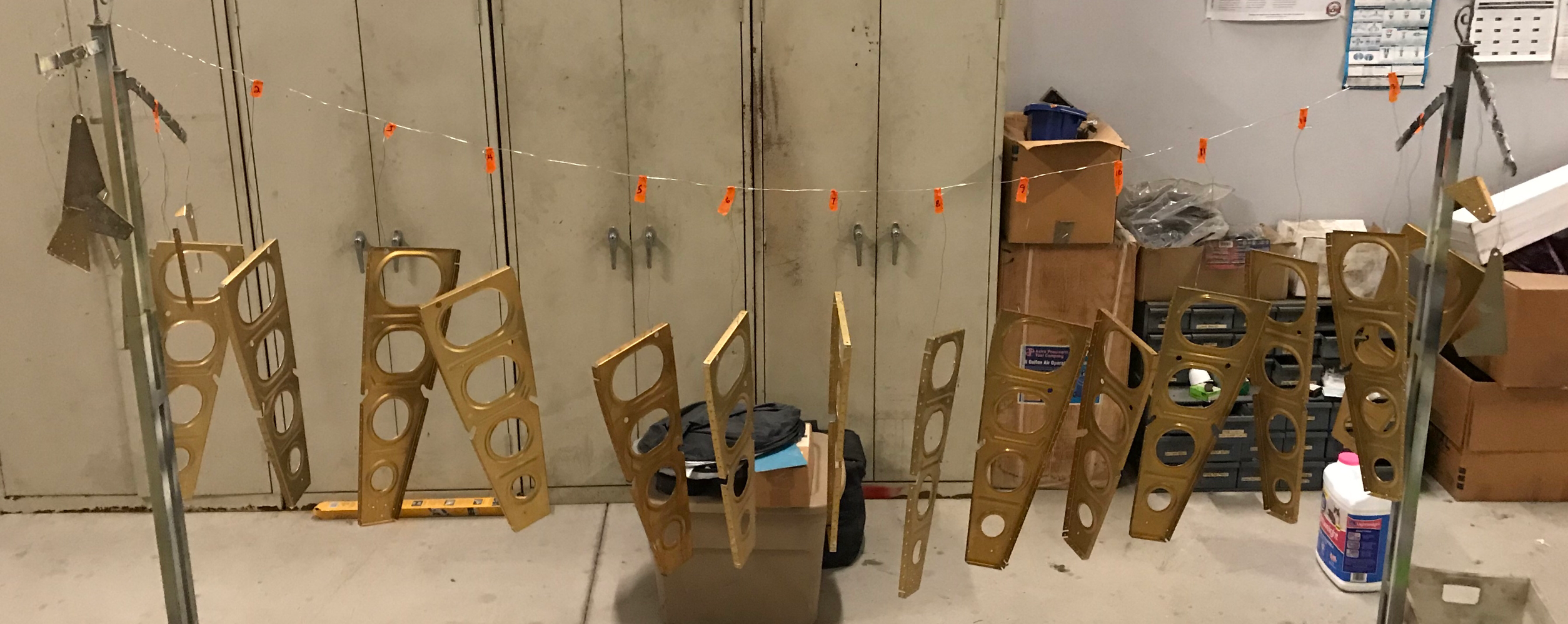
Just like with the Ribs on the Left Wing, I have bins large enough to dip/submerge the Ribs in the appropriate chemical. Initially, each piece is submerged in Alumiprep 33 and then Alodine 1201. After the Alodine, the parts are hung up to dry on my “clothes line”. The orange tabs above each Rib is the numbering system I use to keep each Rib where it is supposed to be and re-installed correctly on the Main Spar after being fitted. Shown below are the 14 Wing Ribs, the parts that make up the Flap Hinge Brackets, and the parts that make up the Torque Tube Support Bracket Assembly.
Today, January 24, 2018
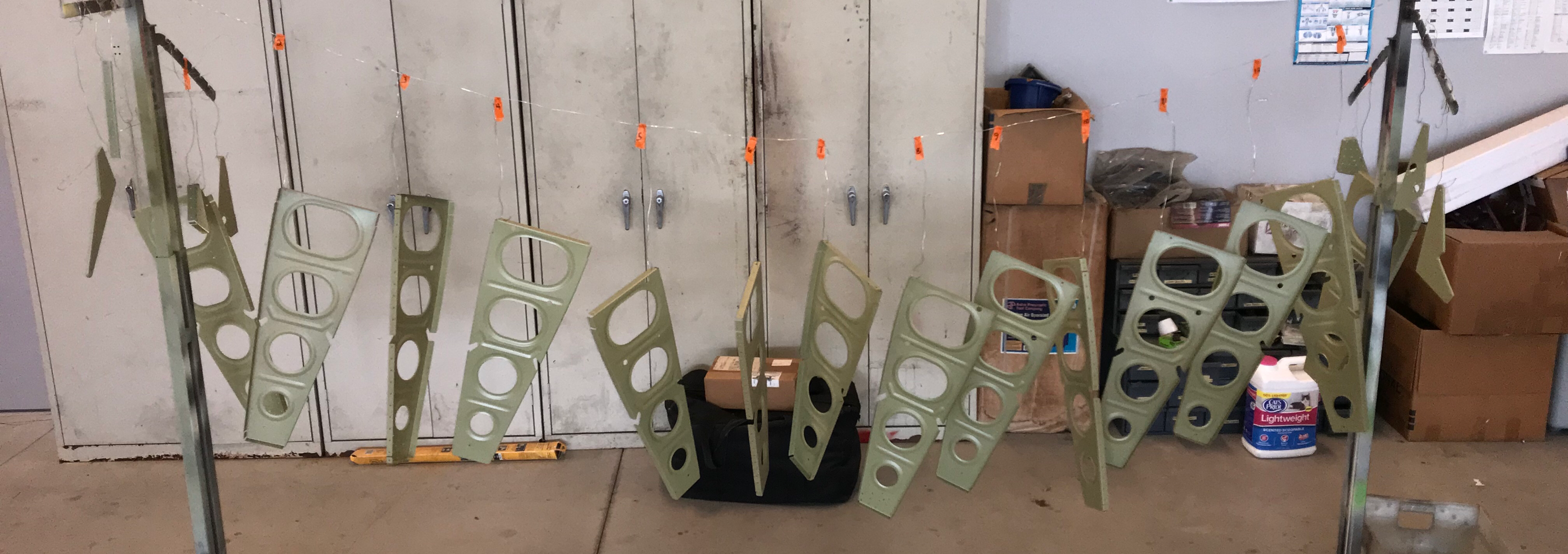
I started today’s session by Akzo priming all the parts that were Alodined yesterday. Below are the parts hanging up to dry on my clothes line.
After letting the parts dry for a couple of hours, I started the initial riveting process. The first parts to get riveted were the Wing Rib #3 and #8, the Flap Hinge Bracket, and the Flap Hinge Rib. There were 16 AN470AD4-7 universal rivets installed on each Rib. The picture below shows each of the Ribs.....one showing the manufactured heads and the other showing the shop heads.
The next parts to be riveted together made up the Torque Tube Support Bracket Assembly. AN470AD4-5 and 4-6 universal rivets were used to complete the assembly.
Finally, per the plans, 12 of the 14 Wing Ribs were re-clecoed to the Righ Main Spar. As I found out on the Left Wing, Wing Ribs 1 and 2 are temporarily left off to aid in the rivet installation of Rib #3, and then Rib #2.
During the next session, I will begin riveting the Wing Ribs to the Right Main Spar.
After I primed the Right Main Spar in Section 13, I was storing it in the same plastic and shipping crate from Van’s. I figured it would be the best way to protect it while it was waiting on its turn on the assembly line.
As I mentioned in my previous post, I’m having to backtrack to Section 14 to complete the initial steps on the Right Wing. The first thing is to cleco the Torque Tube Support Assembly to the Upper and Lower Flanges of the W-1010 Inboard Wing Rib and final-drill #30 the W-1029C Angle to the Wing Rib.. This step went REALLY, REALLY fast, as I already accomplished this while working on the Left Wing.
The W-1025A Flap Hinge Brackets needed to be straightened to remove any bowing from the manufacturing process. This step also went REALLY, REALLY fast....it was also completed with the Left Wing.
The Flap Hinge Ribs, Flap Hinge Brackets, and Inboard Wing Ribs (W-1011-L & -R) were clecoed together and match-drilled to #30 using the Flap Hinge Ribs and Flap Hinge Brackets as drill guides.
The outermost Wing Rib (#14–if you recall my numbering system from the Left Wing) had to have a portion of the Flange material removed (just like the Left Wing). Here is the excerpt describing the area to be removed. I removed this area the same way as before.....I used a small cutting wheel on the Dremel Tool to remove the majority of the material. Once that was complete, I used a small fine hand file and 220 grit sandpaper for the final shape.
The 22 bolts, washers and nuts were removed from the Right Main Spar Assembly and will be set aside for Wing Rib installation in a later step.
All the Inboard and Outboard Wing Rings were clecoed into place on the Right Main Spar. I also clecoed the Right Rear Spar to the assembly to give the Wing Ribs some stability and hold everything somewhat together. This is the Right Wing with all the Wing Ribs clecoed into place. All the common #30 attach holes in the forward Flanges of the Wing Rib and web of the Main Spar were final-drilled. Additionally, all the common #40 attach holes in the Upper and Lower Rib Tabs and Flanges of the Main Spar were also final-drilled.
Now, guess what comes next.....mark the Rib locations on the Main Spar.....remove and deburr freshly drilled holes. Done!
I haven’t updated the blog in the past few days, but I have been working on the Left Rear Spar. So, like on a few previous posts, I’ll catch everything up here. From my last post, I completed the prep on the Rear Spar and primed it with Akzo. I then clecoed it into place on the Left Wing and started to install rivets. The last few days have been spent finishing up the riveting on the Rear Spar.
Note: All of the empty holes you see in the pictures below, will be used to install the Gap Seal later in the build. Additionally, as far as rivet orientation goes, I decided to put the manufactured heads on the aft side of the Rear Spar.....except on the Wing Rib to Rear Spar attach. I followed the preferred method of putting the manufactured head on the thinner material. So, in the pictures below, you will see some of the rivets installed in different directions.....this is why.
Now that the Left Rear Spar has been completed, I’ll start from the outboard end of the Left Wing and work inboard. This is the Outboard Rear Spar Doubler with the eight AN470AD4-4 universal rivets installed. These were very easy to set with a longeron yoke on my hand and pneumatic squeezer.
Here is the opposite side (Outboard Rear Spar Doubler) showing the shop heads.
Some of these rivets were set during the last couple of sessions with a combination of hand and pneumatic squeezer, but I wasn’t able to set the eight that attach the actual Inboard Aileron Hinge Bracket to the Rear Spar. Today, Jeff and I shot these rivets and finished the Bracket install. I used a 3X rivet gun because of the -4 rivets and a tungsten bucking bar. This area used a combination of AN470AD4-4, 4-8, and 4-9 universal rivets. NOTE: contrary to the picture below, the rivets turned out quit nice on the Aileron Hinge Bracket. The “ugly” you on see on the five rivets (left side of the angle) is where the primer flaked off the Angle Bracket.
This is the opposite side of the picture above (Inboard Aileron Hinge Bracket) after all the rivets have been set. You can also see the Service Bulletin Doublers that were added to the Bracket. The Service Bulletin made this area much more “beefy”.
Here is the completed Inboard Rear Spar Doubler. This area used AN470AD4-4 and 4-5 universal rivets. Here is a good picture of the different rivet orientations I talked about earlier.
Here is the opposite side (Inboard Rear Spar Doubler) after all the rivets have been installed.
Previously, I final-drilled the Rear Spar Doubler Plates (Left and Right Wing) to 11/32 as shown below. The Rear Spar Reinforcement Fork already had a corresponding sized hole from the factory and did not need to be final-drilled. These holes will ultimatley become the Rear Spar Attach Holes.
However, once the two pieces were together, the Rear Spar Attach Hole needed to be reamed to 3/8. The plans state that this is critical hole and must be reamed using a drill press and proper sized reamer. My buddy Jeff helped me and we used the 3/8 reamer below to make the final hole. I’ll point it out below.....
Here is the Rear Spar Reinforcement Fork and Rear Spar Doubler Plate riveted to the Rear Spar. You can also see the 3/8 reamed Rear Spar Attach Hole mentioned earlier on the far right. This area used AN470AD4-6 and 4-8 universal rivets and AN426AD4-8 flush rivets.
This is the opposite side (Rear Spar Reinforcement Fork and Rear Spar Doubler Plate) after all the rivets were set.
That will complete this section of the plans for the Left Wing. I will now start this process somewhat all over again and do the Right Wing. I have already prepared most of the pieces for the Right Wing, except for some final-drilling, Alumiprep, Alodine, and Primer. So, the Right Wing “should” go a lot faster.
Now, with that being said, I will have to backtrack slightly here to Section 14 (Wing Ribs) to assemble the Inboard and Outboard Flap Hinge Assemblies, Torque Tube Sub-Assemlies, and attach the Wing Ribs to the Right Main Spar. So, the next post on this section will be when all of that is complete and I’ve progress back to Section 15, Right Rear Spar.
I spent the first few hours of tonight’s session preparing the Left Rear Spar. I used a grey Scotch-Brite pad with the Alumiprep and scratched the surface of the Spar. Then, I used a 2” foam brush to apply the Alodine.
I let the Spar dry for about 2 hours and then sprayed Akzo primer. It turned out okay, but an “artist” always sees his flaws (little dry in spots). The next step is to re-cleco all the parts of the Rear Spar back together and start the riveting process.
Not the best picture, but you can see the Rear Spar and associated parts clecoed back together on the Left Wing Assembly. Now, it’s time to install lots of rivets!
For clarification, the plans DO NOT have you attach the Rear Spar Assembly to the Wing (via the Wing Ribs). This is done in the next couple of steps. They also recommend you cover the Wing Rib attach holes to keep from accidentally installing a rivet. However, I think it might be easier to install the rivets with the Rear Spar clecoed to the Wing:
1. The Wing Rib locations have clecos in them, so you “shouldn’t” rivet that location
2. It will hold the assembly in place, which makes installing the rivets much easier
Tonight is the first night I get to use my new tool from Cleaveland....The Main Squeeze Model 22. I’ve read/heard many reviews of how great the hand squeezer is, so I decided to get one. I’ve been using my buddy’s, but it doesn’t accept different sized yokes. So, if his squeezer did have enough reach, I’d have to use my pneumatic squeezer or shoot the rivet.
Not all of the holes will get rivets during this step, so I had to be careful not to install an errant rivet where it didn’t belong. This is the Outside Aileron Hinge Bracket and the associated Rear Spar Doubler. After reading other blogs/websites, I decided to put the manufactured heads on the aft side of the Rear Spar. The empty holes shown will be used to install Gap Seals in future steps of the build.
Here’s the other side of the picture above showing the shop heads of the rivets. This new hand squeezer is incredible......very minimal pressure is required to set AD4 rivets! The results are very consistent and repeatable.....very impressed!
Here are the rivets installed on the Inboard Aileron Hinge Bracket and Rear Spar Doubler. I also put the manufactured heads on the aft side of the Rear Spar. I still need to install seven rivets (of the eight) that attach the actual Bracket to the Rear Spar. They are some pretty long rivets.....AN470AD4-9! I already set the one in the Bracket in the top left side. Again, these parts were supplied in the Service Bulletin. The empty holes will also be used for Gap Seals.
Here is the opposite side of the picture above. You can see the one 4-9 rivet I set (top center), along with the other four 4-4 rivets. The two angles on either side of the 4-9 rivet were also parts supplied with the Service Bulletin.
This is the third Rear Spar Doubler on the Rear Spar. All the manufactured heads shown here are AN470AD4-4 rivets. Again, the empty holes shown here will be used for attaching the Gap Seals.
This is the opposite side of the picture above and show the shop heads. I can’t say enough about how satisfied I am with the results of the Cleaveland hand squeezer. It is so easy to use and rivets set perfectly. Very happy with this not so cheap purchase.
There are six holes in the Rear Spar Reinforcement Fork that need to have #30 holes match-drilled into the Wing Rib flanges. These six holes are circled in the picture below.
Additionally, all common attach holes were final-drilled #30.....including all holes that will attach the Main Wing Ribs to the Rear Spar.
The holes in the Upper Flange of the Rear Spar that correspond to the three Rear Spar Doubler Plates needed to be countersunk to fit a Skin that has been dimpled for AN426AD3 rivet. I used my homemade guage to determine the proper depth of the countersink. The 16 hole locations are shown below:
The six holes in the Rear Spar Doubler (Inboard)......
.....six holes in the Rear Spar Doubler (Outboard).....
.....and the four holes in the last Rear Spar Doubler.
The next step is to countersink the two rows of holes on the W-1007C Rear Spar Doubler Plates. The bottom row had to be countersunk to accept the head of an AN426AD4 rivet. The top row had to be countersunk to accept a dimpled 0.020 Skin. Since I didn’t have a similar dimpled skin laying around, I looked forward in the plans to see what part would go here. Turns out, the W-00010-L (Left Wing) Flap Gap Fairing gets attached to this hole location. So, I decided to dimple the corresponding six holes in the Fairing and use the actual dimpled Skin as a depth guage. Worked out great. Once I had the depth set on the countersink cage/cutter, I used the same depth on the opposite Rear Spar Doubler for the same holes.
Now for the dreaded instruction that states......
Disassemble all parts. Deburr the holes and edges of all parts
Now that that’s all done.....
I dimpled all the non-countersunk holes in the flanges of Rear Spar (Left Wing for now). Here is a small example.....
Well, that is as far as I can go on the Left Rear Spar until it gets some Alumiprep and Alodine. The Rear Spar is to big to “dunk” and I will need to use a spray bottle and grey Scotch-Brite outside.....a little cold and dark right now!
In the meantime, I treated the Rear Spar Reinforcement Fork and Rear Spar Doubler plate with Alumiprep and Alondine.
Hanging up to dry.....
Tomorrow, I will prepare the Rear Spar and Akzo prime all three pieces. Once they dry, I can start riveting the Rear Spar assembly.
The Left and Right Outboard Aileron Hinge Brackets are now complete. The Right Outboard is on the right (manufactured heads shown) and the Left Outboard is on the left (shop heads shown). I used my pneumatic squeezer to set all 30 rivets.....very consistent results. These Brackets will now be known as W-1014-L & -R and are set aside and to be installed after the Top Inboard and Outboard Wing Skins are riveted in place.
Moving on to the W-1007C Rear Spar Doubler Plates. The single hole on the left of each Plate needs to be final-drilled to 11/32. I used a unibit with a 11/32 step to make the hole on the bottom Plate. The same will be done for the top Plate.
I’ve already prepared the three Rear Spar Doubler Plates for the Left Wing (Part 4), so now I will complete the three Plates for the Right Wing. To start, the W-1007E Plate is aligned under the flange of the Right Rear Spar and the outer most edge of the Spar.....then clamped into place. All the holes on the web will now be match-drilled #30 using the Rear Spar pre-punched holes as a guide. All the common attach holes in the upper flange will be match-drilled #40 in the same manner.
This shows all the match-drilled #30 holes (copper clecos) and #40 holes (silver clecos) completed. I also deburred all the holes and completed the edge work.
The next Plate will ultimately get attached where the Right Aileron Pushrod will pass through the Rear Spar. Here the Plate is clamped (on the opposite side) to the Rear Spar. The instruction say to put the line, previously drawn in earlier steps, centered with the outboard most row of rivets. In the picture, outboard is to the left and you can see the vertical blue line centered on the outboard most row of rivets. I have also traced the Pushrod hole from the Rear Spar onto the Plate The material within the blue will be removed.....just like on the Left Wing. Now, all the holes in the web will be match-drilled to #30 and the holes on the upper flange will be match-drilled to #40.
This shows all the match-drilled #30 holes (copper clecos) and #40 holes (silver clecos) completed. I also deburred the holes and cleaned the edges. Now I have to remove the material within the blue line.
I started by using a #30 drill bit to make a pilot hole in the center of the blue area. Then, I used a unibit to make a 3/4 hole (largest on the unibit). Finally, I used by buddy’s angle grinder with a grinding bit to expand the hole very close to the edge of the blue line. I will use 220 grit sand paper and small fine hand file to match the pre-punched hole in the Rear Spar.
Here’s the finished Doubler after having the material removed.....
.....and here it is on the Rear Spar.
Here is the third and final Doubler for the Right Rear Spar. This Doubler is aligned the same as before.....the vertical blue line centered on the outer most row of holes. Now, the #30 web holes and the #40 flange holes will be match-drilled.
This shows all the match-drilled #30 holes (copper clecos) and #40 holes (silver clecos) completed. Again, I also deburred the holes and completed the edge work.
Due to the manufacturing process, the W-00007B Rear Spar Reinforcement Forks are slightly bent. To remove this bend, I took a 1”x6” block of wood and held the forks down on the table. Then, I slowly bent the opposite end of the Fork to remove the bend. This took a little massaging to get the Forks straight, but it work out pretty well.
The plans now direct you to cleco the W-0007B Rear Spar Reinforcement Fork, W-1007C Rear Spar Doubler.....
W-1007D-L Rear Spar Doubler Plate (Outboard), W-1013-L Aileron Hinge Bracket Assembly to the Main Spar and Rib Assembly to the Rear Spar.
The plans didn’t call for the Outboard Aileron Hinge Bracket and Spar Doubler to be clecoed to the Rear Spar, but I wanted to check the fit and see how the pieces went together.