This blog was created to memorialize the building process of my Van's Aircraft RV-14 and to satisfy the requirements for certification in the Experimental Amateur Built Aircraft category. It will also serve as a central location for ME to reference in the future on processes and techniques I used during the build. Additionally, it will allow my family, friends, and other interested builders the opportunity to follow along during my build…..and might be helpful to someone along the way.
As I mentioned in my previous post, the last remaining steps in Section 17 is the installation of the Landing Light Lenses. I have decided to wait on that for the moment. I feel like I need to do a little more research before I’m comfortable working with the plexiglass (trimming, drilling, etc).
So, I’ll update this section when I start the installation.
Today, we started off by modifying the Wing cradle we built yesterday. The problem was that the portion of the cradle that the Spar rests on was way to high, which resulted in a fairly significant lean of the Spar. So, we took that section of the cradle apart, cut off 3 inches, and reassembled it. It’s much more level now (we should have taken 4 inches, but I’ll live with the way it is now. In the pictures below, you can see a more level appearance.
With that little bit of business complete, we moved on to riveting the Outboard Leading Edge to the Right Wing. I didn’t take any pictures of this side because it looks just like the Left Wing. We started by installing the rivets (LP4-3 and LP4-4) in the Wing Ribs, Main Spar, and Leading Edge Ribs. Next, we installed the rivets in the Upper Leading Edge to the Main Spar and then to the Lower Leading Edge to the Main Spar.
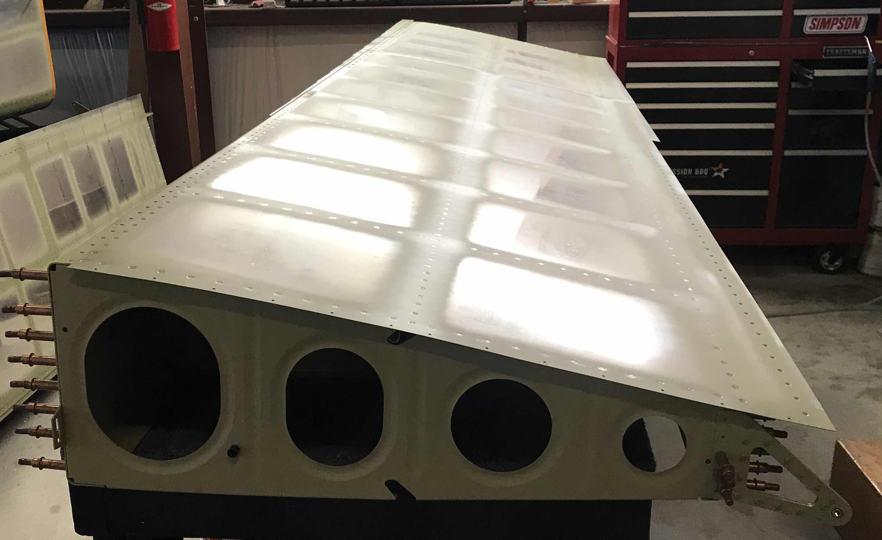
The picture below shows the Right Wing in the cradle with all the rivets installed in the Outboard Leading Edge.
Here are the Left and Right Wings resting in the cradle.
The picture below shows the Left Wing in the cradle with all the rivets installed in the Outboard Leading Edge.
The final step to complete Section 17 in the plans is to install the Landing Light Lenses. I’ll need to study the plans to see if now is the right time to complete this step OR should we wait until after the Landing Lights are installed. More on this in the next post.
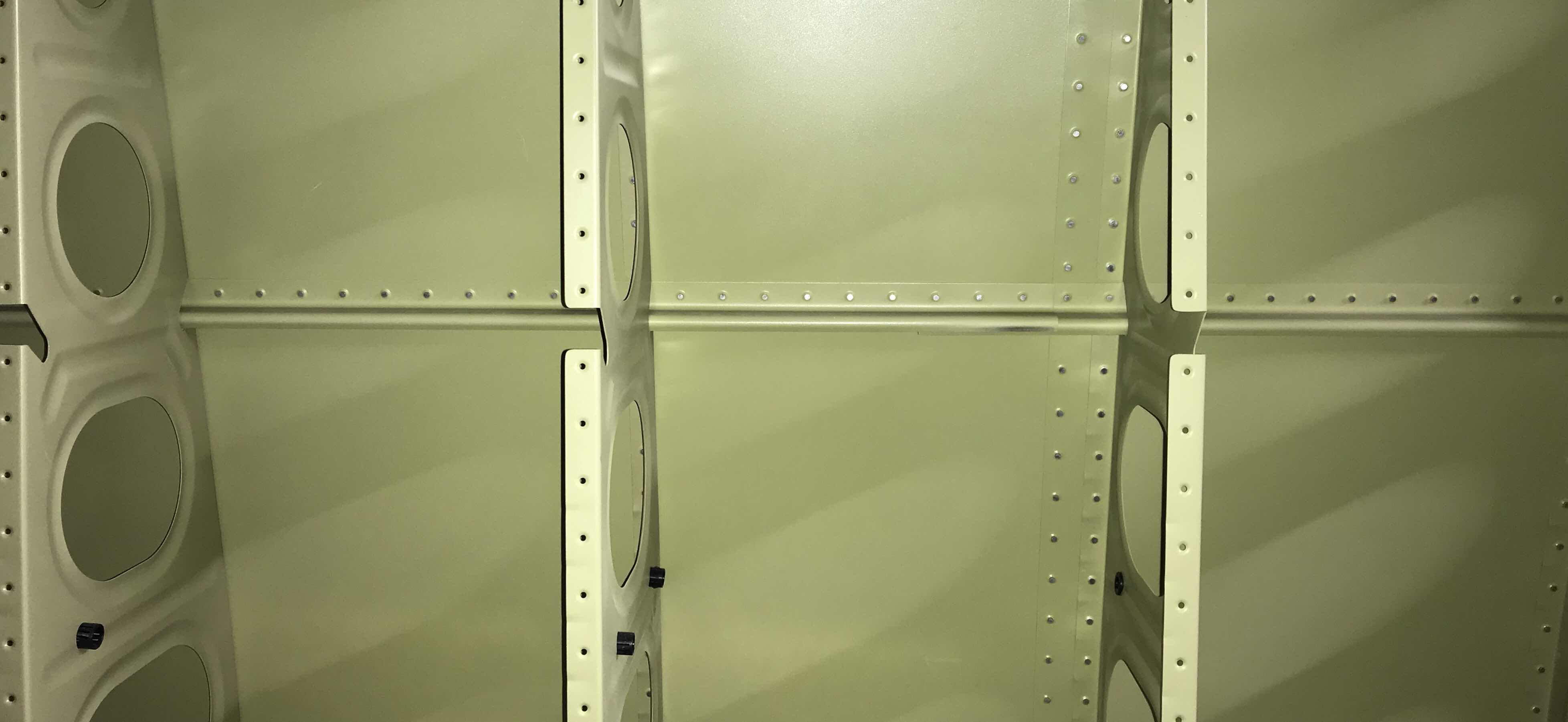
Today was a BIG day in Section 17.....we joined (riveted) the Left Outboard Leading Edge to the Left Main Spar. The 63 rivets for the top are located just above the black line in the picture below.
The 62 rivets on the bottom are located just above the black line in the picture below. (One of the rivets locations will be used for the installation of the pitot tube at some point in the future, which is why there is only 62 rivets on the bottom and not 63 like on the top). Additionally, the six Wing Ribs seen below (and area in the black circle) had to be blind riveted to the Main Spar AND the Ribs in the Leading Edge. The three Wing Ribs on the right used LP4-3 rivets and the three Wing Ribs on the left used LP4-4 rivets. The area in the black circle below used universal AN470AD4-5 rivets.
Here is the front (or top) of the Left Wing in the wing cradle with all the rivets installed in the Outboard Leading Edge.....
.....and the back (or bottom) of the Left Wing with all the rivets installed in the Outboard Leading Edge.
I will have to make a few adjustments to the Wing cradle tomorrow to level out the Main Spar. Otherwise, the cradles are working great. We will attach (rivet) the Right Outboard Leading Edge to the Right Main Spar tomorrow.
I’m at a point where the Wings are starting to get much bigger. So, I needed to build something to “hold” them. While looking at Shawn’s Build Site, I found a link to Mouser’s RV-10 site that contained plans for building Wing Cradles. So, I used this information to build my wing stands.
After completing Section 16 (Top Wing Skins), we went back to the Outboard Leading Edges. We started by assembling
the Stall Warning Subassembly as shown in the plans excerpt below.....
Once assembled, it was installed on the W-1008-R Spice Rib as shown in the plans excerpt below.....
The picture below shows the Stall Warning Vane extending from the slot I previous made in the Left Outboard Leading Edge Skin (Part 7).
This is the inside bay of the wing that houses the Stall Warning Subassembly. In the picture below, it is installed to the Splice Rib with two 832 x 1/2 screws.
The next step was to Final-Drill .375 the hole for the tie-down on the bottom of both Leading Edge Skins. This hole was pre-punched by Van’s to #40 and had to be enlarged to 3/8 to allow the tie-down ring to be inserted through the Skin. After I initially enlarged the hole to 3/8 (Left Wing shown below), it was “slightly” off centered. So, after some filing and sanding, I got the result pictured below. I also cut the 3/8 hole in the Right Wing, but I will make any final alignments required when it gets clecoed the the Right Main Spar for riveting.
Now for the fun part.....preparing to install the Outboard Leading Edges to the Main Wing Spars! Pictured below is the overall view of the Left Wing with the Outboard Leading Edge clecoed into place.
Here is a little closer view.
Tomorrow, we will start riveting the two assemblies together.
Today, we installed the final 10 rivets in the Outboard Aileron Hinge Bracket on the Left Wing. I forgot to take a close up picture, but it’s the 10 rivets in the circle below. This is the same location we completed on the Right Wing on Sunday.
This morning we started bucking rivets in the Inboard and Outboard Top Wing Skins for the Left Wing....lots and lots of rivets!!
Here is the Left Wing with all the rivets installed, including the J-Stiffener.
Another angle of the Left Wing.....
In this section of the Wing, you can see the two vertical rows of rivets where the Inboard and Outboard Skins overlap. Additionally, this is also the area where the two J-Stiffeners (long and short) overlap.
The inboard section under the Wing Walk showing the J-Stiffener-short installed.
After all the rivets were installed, the seven #19 holes had to be countersunk for the dimpled skin of a #8 screw....you can see them here.....
Tomorrow, we will install the last 10 rivets in the Outboard Aileron Hinge Bracket and Section 16 will be complete!
During today’s session, we also riveted the J-Stiffeners in both Outboard Leading Edges. Each J-Stiffener received 62 rivets. Below is a picture of the Left Outboard Leading Edge with the J-Stiffener riveted into place (horizontal row across the top).
This is the inside of the same Leading Edge and you can also see the J-Stiffener riveted into place. As I mentioned in a previous post, the portion of the J-Stiffner in the Landing Light was painted flat black....the remainder of the J-Stiffener is in Akzo green.
Yesterday, we set up the countersink cutter and made one countersink (of the seven) to the #19 screw holes for the nutplates on the inboard edge of the Top Skin. Today, we finished countersinking the remaining six holes. Shown below are all seven holes on the inboard edge that were countersunk. They were countersunk deep enough to accept the dimpled skin of a #8 screw. (The countersink on the far left near the Spar was previously countersunk and will ultimately be used as a fuel tank screw.....the hole on the far right is not countersunk, but dimpled).
The last step to complete the Right Wing (for this section), was to install the final 10 rivets in the Outboard Aileron Hinge Bracket Assembly. Five rivets were installed between the Assembly and the Trimmed Outboard Wing Rib (first picture) and five between the Assembly and the Rear Spar (second picture). I tried to follow the “rule of thumb” regarding the manufactured head of the rivet being placed on the thinnest material. However, I was not able to come up with suitable installation method to accomplish this. I initially tried squeezing the rivets with the pneumatic and hand squeezers. I have a 3” standard yoke and 2” Longeron yoke. Neither of the two were usable in this location. I couldn’t shoot the rivets from the “inside” of the Wing because of space issues. So, I made the command decision to install the rivets as you see below. We ended up shooting all 10 with a 3X rivet gun and bucking bar and they came out very nice.....I’m please with the results.
Now that the Right Wing is complete....we moved on to the Left Wing. We were able to install all of the rivets in the Top Inboard Wing Skin before we called this session for the night. We will start with the Top Outboard Wing Skin in the morning.....
We finished riveting the J-Stiffener into the Left Wing. There are only 10 universal rivets left to set in this Wing that connects the Outboard Aileron Bracket to the Rear Spar and Rib. We will set those 10 rivets during the next session.
Here it’s he opposite side showing the riveted J-Stiffeners.
Just a close up of a section to J-Stiffener riveted to the Top Skin.
View of the Right Wing laying flat with all the rivets installed.
In addition to the 10 universal rivets mentioned above, seven #8 screw holes will need to be countersunk to fit the Skin of a #8 dimple. In the picture below, the countersunk hole on the right is one of the holes mentioned in this section. (The one one the left was completed in an earlier section).
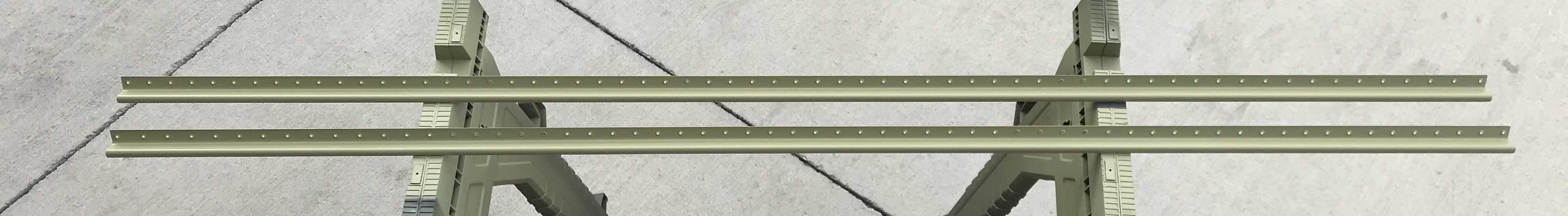
As I mentioned in the last Outboard Leading Edge Post (Part 25), the J-Stiffeners needed to be prepared prior to installation. During today’s session, the J-Stiffeners were treated with Alumiprep, Alodine, and Akzo Primer. The picture below show the two Stiffeners drying after being primed.
Pictured below in the Right Outboard Leading Edge with the primed J-Stiffener clecoed into place. I also painted flat black the section of the J-Stiffener that extends into the Landing Light Bay. The Left Outboard Leading Edge was prepared in the same fashion.
The two J-Stiffeners (one for the Right Outboard Leading Edge Skin and one for the Left Outboard Leading Edge Skin) will be riveted into place tomorrow.
Well, we finished installing the rivets in the Left Wing Skin (minus the J-Channel).
Below is the inside of the Right Wing showing the Wing Box J-Stiffener-Long and Wing Box J-Stiffeners-Short clecoed into place. As I mentioned before, the J-Stiffeners have not been treated with Alumiprep, Alodine, or Akzo Primer (hence the shiny alumimum).
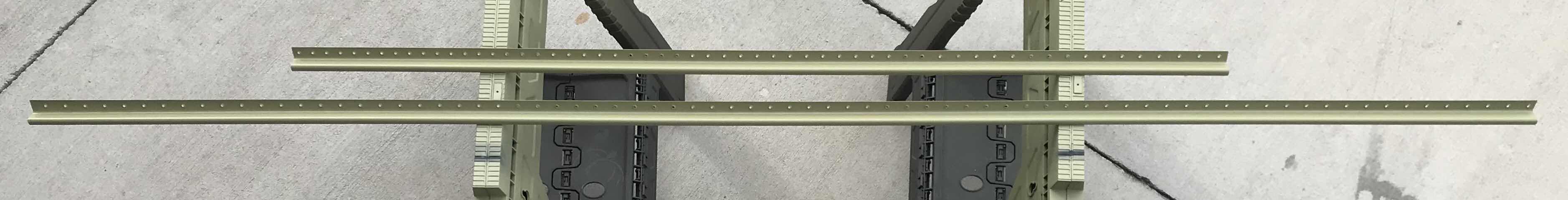
So, in order to finish the Wing, we had to prepare the J-Stiffeners. The -Long and -Short were treated with Alumiprep, Alodine, and Akzo Primer and are shown below drying after being primed.
After they were finished drying, we install them in the Wings.....looks better in Akzo green! They now need to be riveted into place tomorrow.
Below, is the prepared VA-195B Stall Warning Keeper Plate (left) and VA-195A Stall Warning Mount Plate (right). Both pieces were treated with Alumiprep, Alodine and Akzo and will be used to assembly the Stall Warning System in the Left Wing.
After “completing” the Outboard Leading Edges, we shifted our attention back to the Top Wing Skins. All the rivets need to be bucked in both Top Wing Skins. During today’s “second” session, be installed 82 of these rivets. Below is a shot of the area we started working on. Additionally, there will be a J-Channel installed in the horizontal row of holes after the Skins get riveted. In order to get the tightest Skins possible, the plans state to rivet from the center of the Skin and work toward the tips and roots.
We finished riveting the Right Outboard Leading Edge Skin (again, minus the J-Channel) during today’s session.
Another view of the inside Ribs with the J-Channel clecoed into place.
Like I said yesterday, this is a cool shot! Additionally, the aluminum J-Channel you see clecoed here will also have to be painted flat black to match the Landing Light Bay. I will do this after it gets primed.
Below are the completed Left and Right Outboard Leading Edge Skins awaiting the J-Channels (the row of clecos in each Skin). I will alumiprep, alodine, and prime the J-Channels in the next few days and rivet them into place. Then, the Skins will really be complete.
We started today’s session where we left off yesterday. I guesstimated we had about 50 rivets to go.....we had 52. (Well, kinda sorta....still have to install the J-Channel, but it has not been treated with Alumiprep, Alodine, or primer yet). So, we will move on to the Right Outboard Leading Edge and do both J-Channels together at the end.
This is just a close up shot of the Landing Light Bay with the W-00017 Mount Bracket installed. I will have a few places to touch up after bucking the rivets (from the bucking bar), but I think it’s a cool shot with the flat black paint and shop head of the rivets.
Moving on to the Right Outboard Leading Edge. It’s shown below in the cradle with all the Ribs clecoed into place. This view is of the bottom of the Wing.
Below you can see a side view of the seven Ribs.
We were able to install 70 rivets before we called it a day. We will pick up here tomorrow.