This blog was created to memorialize the building process of my Van's Aircraft RV-14 and to satisfy the requirements for certification in the Experimental Amateur Built Aircraft category. It will also serve as a central location for ME to reference in the future on processes and techniques I used during the build. Additionally, it will allow my family, friends, and other interested builders the opportunity to follow along during my build…..and might be helpful to someone along the way.
I started today’s session were I left off yesterday. I started by machine countersinking the remaining 36 holes on the bottom row of the Left Fuel Tank Skin. Now, all 145 holes in the Left Fuel Tank Skin have been countersunk.
Next, I machine countersunk all 145 holes in the Right Fuel Tank Skin. As you can imagine, countersinking all 181 holes took up a bulk of my work session today.
I finished today’s session by fabricating the T-00003 Tank Stiffeners for both Fuel Tanks from stock J-Channel. To start, each of the Stiffeners were measured and cut (with my bandsaw) to a length of 54”. I then drew a centerline down the length of the flange of the J-Channel, marked and drilled a #40 hole in the flange at 5/16” and 1/4” from one end, and clecoed that hole to corresponding hole in the Tank Skin. Then, the centerline on the flange was “centered” in each of the corresponding Tank Skin holes and match-drilled to #40. Each J-Stiffener has a total of 55 holes.
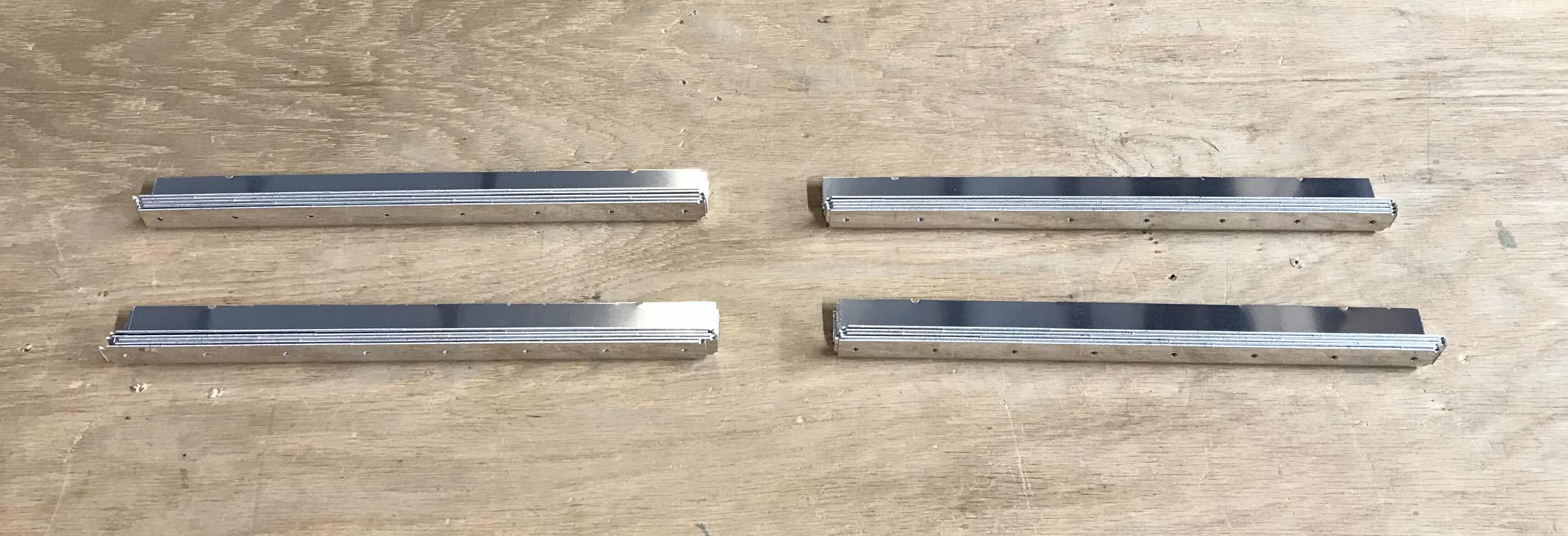
This picture shows the J-Stiffener after all the holes were match-drilled, deburred, and the edges cleaned.
The last step was to dimple all 110 holes in the J-Stiffeners.
This is just a close up of the dimpled holes in the two J-Stiffeners.
This session concentrated on countersinking the row of holes in the T-00001-L & -R Fuel Tank Skins that attach the Skins to the T-00002 Tank Baffle to fit the head of a AN426AD3 rivets. Typically, material that is .040 thick gets countersunk (and material thinner gets dimpled). The Fuel Tank Skins are .032 thick, but will have the Tank Baffle underneath it. The plans state:
“Countersinks that are up to .005 too shallow are acceptable and preferable to countersinks that are too deep”.
*****If you recall from earlier in the Wings build (Top Wing Skin, Part 11), the same statement was made concerning the holes in the Inboard Top Wing Skins that were countersunk.*****
I started by making a cut, then checking the depth with the AN3 rivet. Based on the fit of the rivet head, I would adjust the depth of the countersink cutter, make another cute, and re-check. This process continued until I achieved what I felt to be the proper depth. This process took a little while to get the results I wanted, but definitely worth it in the end.
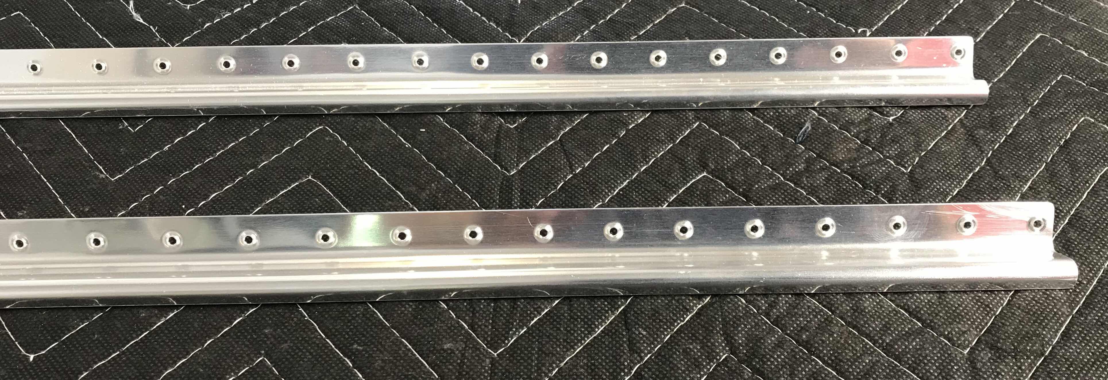
In the picture below you can see a portion of the holes that were countersunk in the row with clecos on the bottom of the picture.
I was able to finish the top row of 73 holes and 36 of the 72 holes on the bottom row in the Left Fuel Tank Skin. I will complete the remaining holes and the Right Fuel Tank during the next session.
*****This post includes work completed on Tuesday, June 26th and Thursday, June 28th*****
Tuesday, June 26, 2018:
The next step in the plans is working with the outer Skins and parts of the Fuel Tank. Now, I’ve read several builder’s blogs/websites and Van’s Air Force forum postings warning NOT to prime ANTHING on the inside of the Fuel Tanks. If those warnings aren’t good enough, the builder’s plans from Van’s says.....
NOTE: Do not prime any areas that will be in the inside of the tanks.
So, I will not prime anything on the inside of the Fuel Tanks. So, my next question was regarding Alumiprep and Alodine. The same Van’s Air Force Forums advised that Alodine was fine as it is a chemical conversation that won’t “come off” like primer potentially will. My plan will be to Alumiprep and Alodine all the parts and pieces that make up the entire Fuel Tanks (both inside and outside). Then prime some of the smaller parts that get assembled on the outside of the Tanks. Finally, once the Fuel Tanks are completely finished, leak checked, and ready to be installed on the Wings.....I will prime the entire outside area of the Tanks (minus the upper and lower Skins). As with all sections of the Wings so far, the plans give you the option of building one Wing at a time or both at the same time. I will continue to build them both at the same time.
Shown below is the Left Wing Fuel Tank Skin (still with the protective plastic on it). The Right Wing Fuel Tank Skin looks identical with the exception of the fuel filler hole located on the opposite side of the Skin than shown below.
This is the “back” side of the Fuel Tank known as the T-00002 Tank Baffle.
Pictured below is the front leading edge of the Left Fuel Tank Skin with Tank Baffle clecoed into place.....
.....and the back of the Left Fuel Tank.
And here is the front leading edge of the Right Fuel Tank Skin with the Tank Baffle clecoed into place.....
.....and the back of the Right Fuel Tank.
The Tank Baffle orientation for both Fuel Tanks was very specific. The proper orientation places the flange with the “extra” hole on the bottom. This was very easy and obvious to figure out looking at the Tank Baffles.
In Part 1, Roger and I prepared all 14 Tank Ribs. In Part 2, the two T-00005A Tank Stiffeners were prepared. In Part 3, the 20 T-00004 Tank Stiffeners and the 14 T-1012 Tank Attach Zees were prepared. Now, as some builder’s have done, I wanted to test fit all the pieces to get an idea of how things fit together.
Below, is the “inside” of the Left Fuel Tank with the seven Ribs and 11 Tank Stiffeners (you can see them on the bottom between the Ribs) clecoed into place.
This is also the Left Fuel Tank, but with a better view of several of the Tank Stiffeners.
This is the Left Fuel Tank with the Tank Baffle and seven Zees have been clecoed into place. I had no difficulty fitting the parts together (I didn’t think I would). I mainly wanted to get a visual of how things went together in order to keep it all straight in my head since I’m building both
Tanks at the same time.
I also test fitted the Right Fuel Tank as I did above with the Left. All the parts and pieces went together with no real issues, but again, I wanted to get things straight in my head.
The work shown below was consolidated into one blog entry, but the work took place over Friday (June 22), Saturday (June 23) and Sunday (the date of this blog entry).
The T-00004 Tank Stiffeners are shown below in their “raw” form as they were when they arrived in the kit. They come connected in four long pieces of aluminum and need to be cut and trimmed into individual pieces. Each Wing will get 10 of these Stiffeners, so two strips are for the Right Wing and two strips are for the Left Wing. There are a total of 20 Stiffeners shown below.
After removing the blue plastic, I used my bandsaw to cut the pieces into individual pieces.....these are the four strips shown above.
After cutting them into 20 individual pieces, they had to be trimmed into their final shapes. The corners of each Stiffener had to be removed to form the angles you see below on each end. Again, I also used my bandsaw to remove the little “triangles” from the Stiffeners. (All 40 triangles are in the little pile.....whatever)!
The next step was to clean the edges, dimple the #40 holes, and scuff the bottom of the Flanges that will make contact with the Tank Skins (the Flanges with the dimples on them). After all that, here are the 20 completed T-00004 Tank Stiffeners. Since these Stiffeners will be installed on the inside of the Fuel Tanks, the will NOT be primed. However, I will treat them with Alumiprep and Alodine prior to final assembly.
NOW.....In Part 1, Roger and I prepared the T-1003B-R & -L Inboard Tank Ribs. However, I was not completely satisfied with our results and ordered two new Inboard Tank Ribs from Van’s. Now, two of the four VA-141 Finger Strainer Flanges (one in each Rib) already had corresponding holes in the Inboard Tank Ribs prepared by Van’s.....the other two have to be prepared by the builder. This is where my dissatisfaction comes from with the preparation of the Flanges/Ribs in Part 1. Below is my second attempt.....which turned out much better to my liking. In the picture below, the 3/4 inch hole and five #30 holes on the bottom left were the ones prepared by Van’s....the same arrangement on the top left were the one’s I prepared. To make this outcome better, I positioned the Finger Strainer Flange on the Inboard Tank Rib and then traced the Flange onto the Rib with a blue sharpie. By doing this, I was able to find the center of the enlarged 3/4 hole. Then the five #30 holes were Match-Drilled to the Rib. I was much happier with this result. I used the same method for Left and Right Inboard Tank Ribs.
Here you can see the orientation of the Finger Strainer Flange and the Inboard Tank Rib after being Match-Drilled #30.
Shown below are the completed T-1003B-R & -L Inboard Tank Ribs, two T-00005A Tank Stiffeners, two T-00005B Vent Line Clips, and 14 T-1012 Tank Attach Zees.
The 14 T-1012 Tank Attach Zees will be primed (because the are on the outside of the Fuel Tank) and were prepared with Alumiprep and Alodine. You can see the Zees getting their Alodine bath below.
After drying overnight, the 14 Tank Attach Zees were sprayed/primed with Akzo.
Then, 12 of the Attach Zees received 36 (three on each Zee) K-1000-3 nutplates. AN426AD3-3.5 rivets were used to attach the nutplates to the Zees.
Well, the last session was the final workday for my stepdad during this visit. He is going to head home and wait for the next trip. However, while he was here helping me, we were able to install 2,183 RIVETS in the Wings and put in a total of 55.2 HOURS of work. I can’t thank him enough for his help....the Wings look like Wings now! This was my stepdad’s third “working vacation” and we seem to always make huge gains while he is here. Thanks again Roger.
So, moving on with the Fuel Tanks. Pictured below is the T-00005 Tank Stiffener. It needed to be separated into two T-00005A Stiffeners and two T-00005B Vent Line Clips. The two holes in the right end of the Stiffener were Final-Drilled to 7/16 prior to the picture.
Below shows the markings I made on the Stiffener where the excess material will have to be removed. I used my bandsaw to make the initial cuts and 220 grit sandpaper for the final trimming.
Here is the two T-00005A Tank Stiffeners after I removed the excess material. I need to clean up the edges and dimple the #40 holes in the flanges.
The next pieces to get prepared are the T-1012 Tank Attach Zees. The first step was to Final-Drill all the #40, #30, and #12 holes in each “strip”.
Next, all the #40 holes were countersunk to accept the head of a AN426AD3 rivet. In order to do this, I clamped the “strip” of Attach Zees to my workbench and place wood blocks under the #40 hole I was countersinking. I then moved the wood block from hole to hole. Seemed to work out pretty well.
Here is closeup of several of the countersunk #40 holes.\
After the countersinking was complete, the Attach Zees had to be separated into individual pieces. I used my bandsaw as shown below to make the cuts.
Here are the 14 Attach Zees after being separated.
After separating all 14 Attach Zees, I used the bench grinder to clean up some of the major burrs on each individual piece. I used 220 grit sandpaper to make the final trimming. Shown below are the 14 Attach Zees, two T-00005A Tank Stiffeners, and two T-00005B Vent Line Clips (as mentioned earlier) all prepared and ready for their next step.
Since I decided to do additional research on working with the plexiglass Landing Light Lenses, we started working on Section 18-Fuel Tanks.
Here are all 16 of the Ribs that will make up both Fuel Tanks.
To start, we made sure all the Ribs were perpendicular to the Rib webs and fluted them as necessary. Next, we Final-Drilled all the #30 and #40 holes in the tank Ribs. In the picture below you can see the two VA-141 Finger Strainer Flanges clecoed to the T-1003B-R Tank Inboard Rib (the T-1003B-L Tank Inboard Rib looks the same, just opposite). The 3/4 hole in the bottom of the Ribs were already pre-drilled from Van’s, but we had to cut the top 3/4 hole with a step drill. The plans provide specific measurements from the Flange edges to drill the hole. Once the 3/4 hole was cut, the #30 holes in the Finger Strainer Flanges were Match-Drilled and/or Final-Drilled. (This was done for all four Finger Strainer Flanges....two for the Left Tank and two for the Right Tank).
Now, it was time to debur the holes and edges....then dimple the #40 holes. Pictured below are the T-10003B-R & -L Tank Inboard Ribs.....