Saturday, February 29, 2020

Fuselage, Rudder and Brake System (Part 8)

Today’s session was very long and very productive.  To start off, the CS-00018-L & -R Left and Right Brake Pedal Assemblies were attached to the WD-655-L & -R Rudder Pedals.  The plans call for a mixture of hardware to make the attachments.  Here is what the plans recommend:
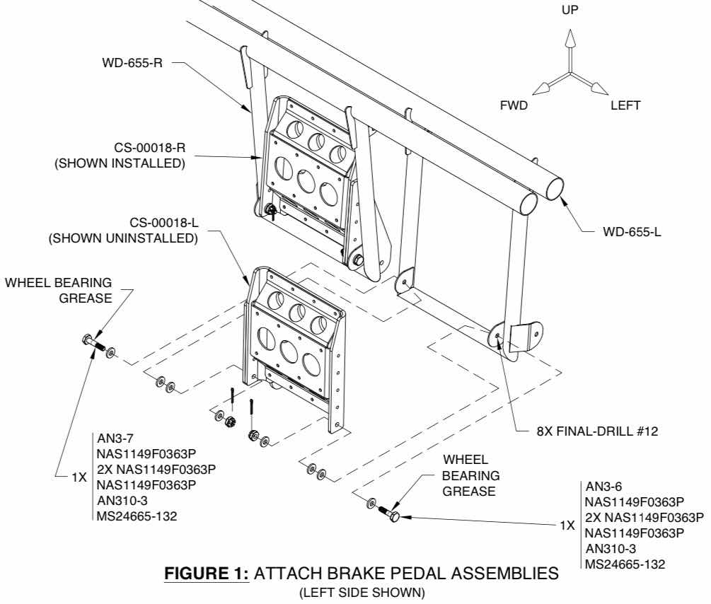
The plans also make three statements regarding this portion of the installation:

1.  “A balance must be struck between free play and friction such that both are minimized.  The brake pedal assemblies much be secure but must also rotate by gravity alone before the cotter pins are installed”.

2.  “Due to manufacturing tolerances, it may be necessary to use a different mix of washers than what is shown in Figure 1.  If required, use a heavy soft-faced hammer to make slight adjustments to the brake pedal mounting tabs”.

3.  “Tighten the nuts and bolts until they are finger-tight.  DO NOT use standard torque values”.

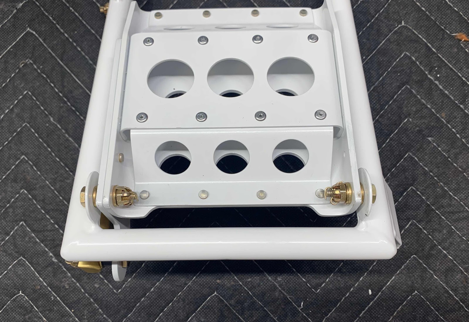
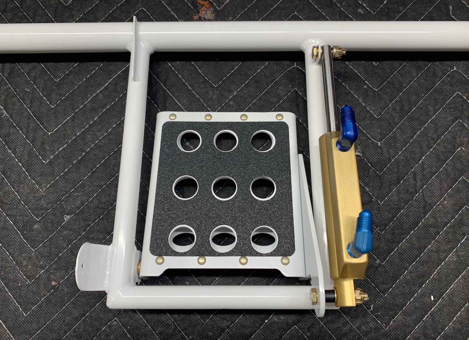
Sooooo, with all that, I started off using the recommend hardware for the installation.  However, the hardware used in the final assembly was just a little different than shown above.  There wasn’t a huge variation....such as using a skinnier NAS1149F0332P washer versus a fatter NAS1149F0363P washer.  It worked out to my satisfaction and, to the best of my knowledge, complies with #1 and #2 above.  Here is what the first assembly looks like with the installed hardware.

Once I completed all four Brake Pedal to Rudder Pedals assemblies, I moved on to the next step.....attaching the four Brake Master Cylinders to the same assemblies.  Here is how they get assembled.....

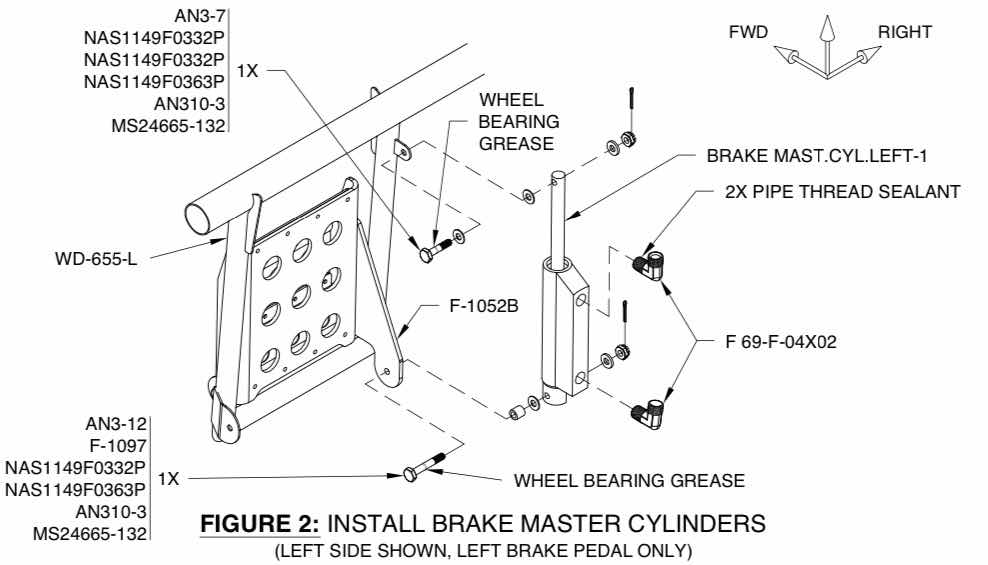
In the picture below, you will notice the two blue elbows attached to the Master Cylinder.  These DID NOT come with kit from Van’s.  In Section 31, Fuel System, I detailed the purchase and installation of the cabin fuel lines from Aircraft Specialty.  I also said I would purchase the Cabin Brake lines from the same company....I did (more on that later).  The blue elbows were included in the kit from Aircraft Specialty.  Here is the first Brake Cylinder install.....

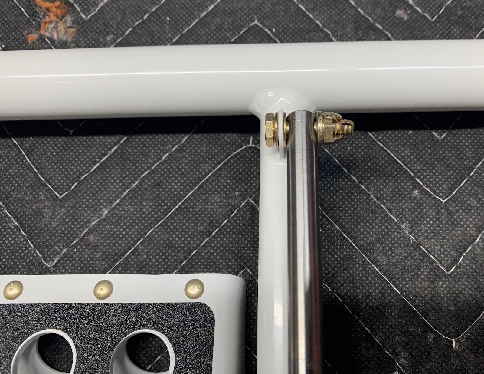
.....a close up of the bottom.....

......and a close up of the top.

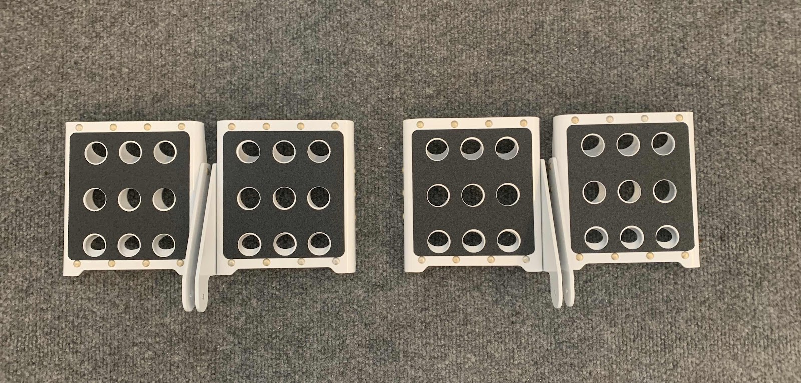
These are the Rudder and Brake Pedals for the pilot side (left).....

.....and the co-pilot side (right).

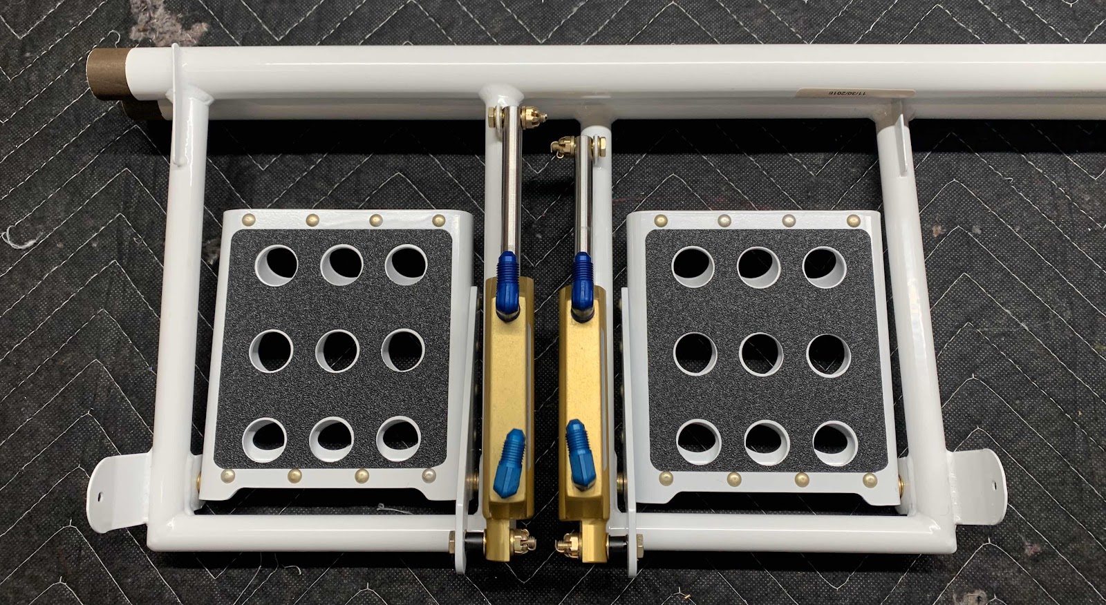
This is an overall view of all four Brake Pedals attached to the four Rudder Pedals.....

.....and what they will look like in the plane.


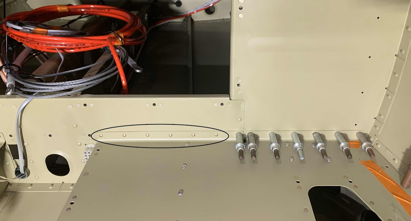
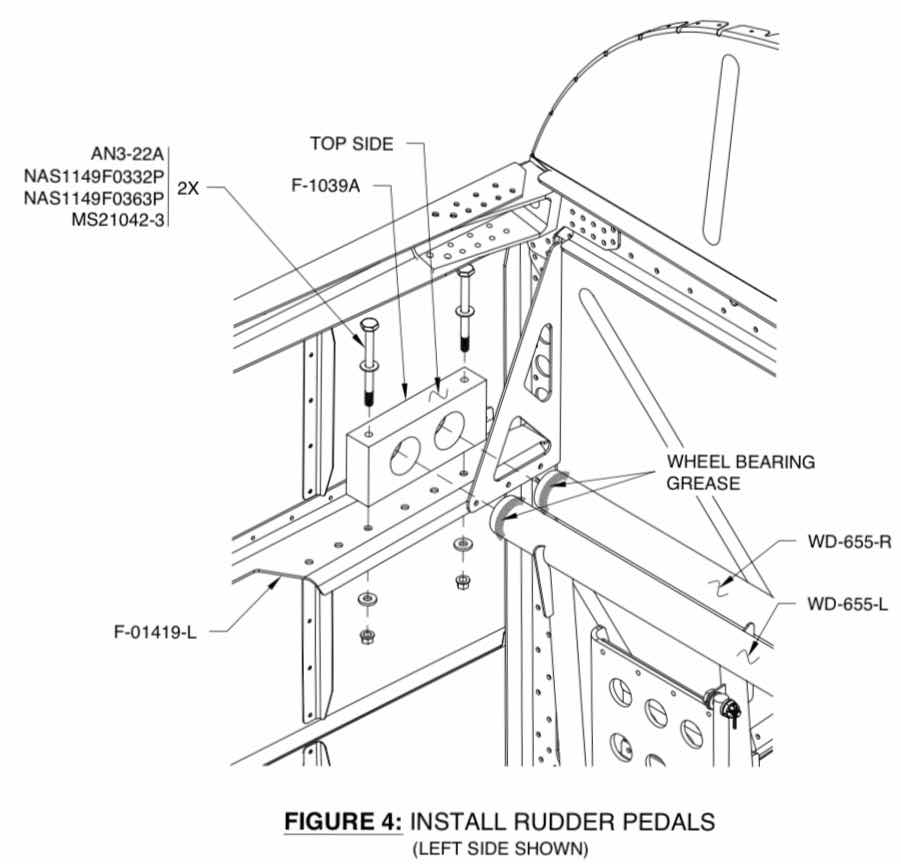
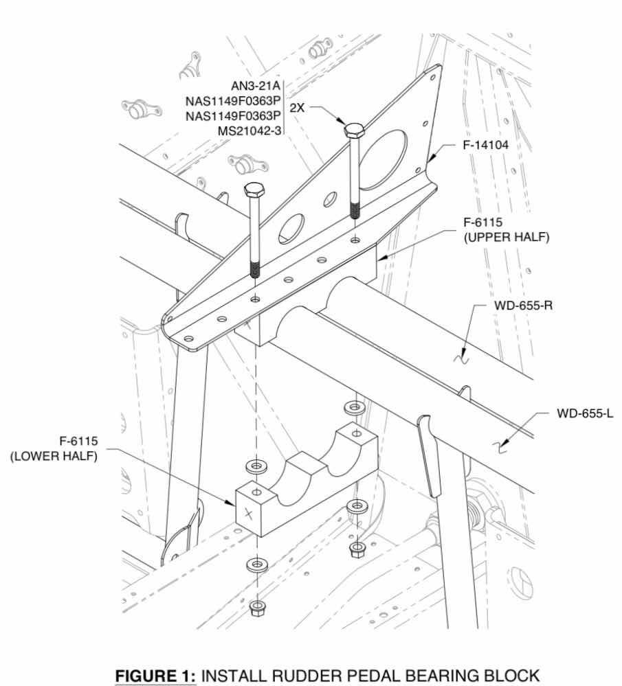
The next step is to install the Assemblies to the airplane.  Here is the install procedure from the plans.  The ends of the Rudder Pedals are coated with AeroShell #5 grease prior to being inserted into the F-1039A Rudder Pedal Bearing Blocks (prepared in Part 6).  The Bearing Blocks were then attached to the airplane with the indicated hardware.

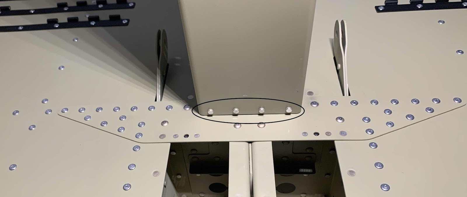
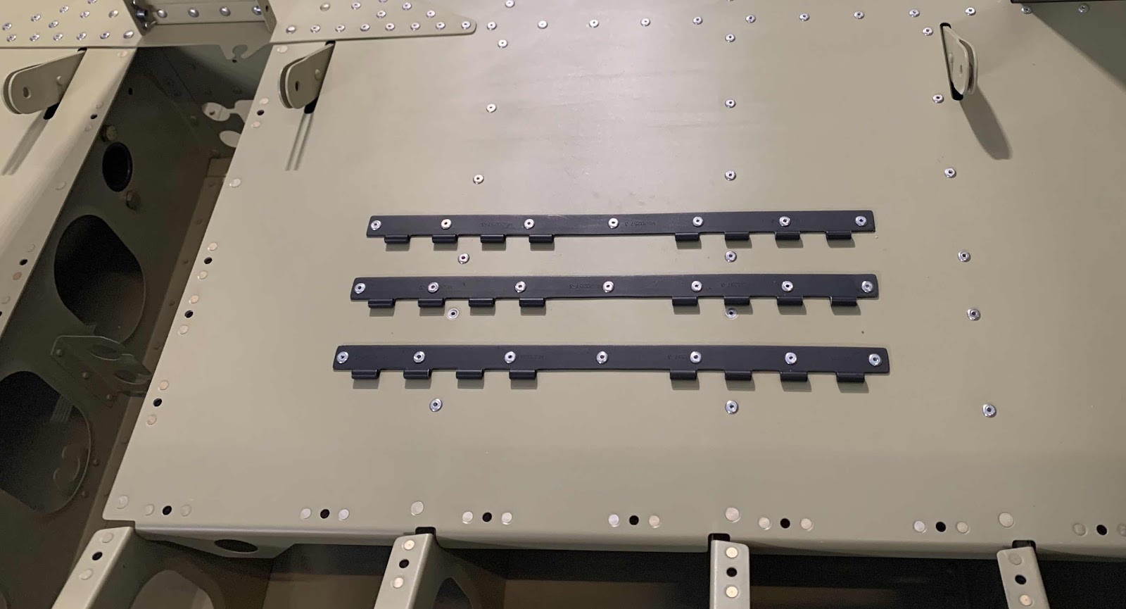
Once the left and right sides were installed to the airplane, the Upper and Lower Halves of the F-6115 Bearing Blocks were installed as shown below.

Here is the finished product on the airplane.....

.....a close up of the co-pilot side (right).....

.....and pilot side (left).

Monday, February 24, 2020

Fuselage, Rudder and Brake System (Part 7)

In Part 5, I assembled and riveted together the four Brake Pedal Assemblies.  However, before I continue with this section and attach them to the Rudder Pedals, I want to put some type of anti-slip on them.  I decided to use some black generic non-skid wing walk from Van’s.

First, I used a paper cutter to make four 4.25” x 4.50” individual pieces.  Then, I taped each piece to the Brake Pedal as shown below.

In order to get the hole locations in the Brake Pedals, I turned the Pedal over and marked the locations with a fine tip sharpie.  The three holes in the middle of the Pedal were very easy to trace the entire circle.  I was only able to get a half hole trace on the six other holes, but it was enough.  (A better way to have done this, would have been to trace the holes PRIOR to the assembly of the Brake Pedal).

Once all the holes were traced I used this punch set to “punch”out the holes in the wing walk.

Here is the whole set.

Now, the holes in the Brake Pedal are 3/4”, so I used a 13/16” punch so the wing walk holes would be slightly larger.  I had to use a little bit of “calibrated eyeball” to get the larger punch evenly around the smaller traced hole.  It wasn’t to hard and it turned out pretty good for just eyeballing it.  With the larger punched holes in the wing walk, I feel like there is less of a chance of peeling it off with my foot if the wing walk is not right on the edge of the Pedal hole.  We’ll see if that theory is accurate.

Once the nine holes were punched in each piece of the wing walk, I used this corner punch purchased from Michael’s to round the four corners of each piece.  This punch is designed for paper, but did a very good job of cutting the tougher wing walk material.  The cutter has two different cut sizes....a small one (the one I used) and a large one.  I thought the smaller one looked better. 

After the holes were punched and the corners were rounded, I peeled the backing and stuck the wing walk to the Pedal.  Here is the first completed Brake Pedal.....you can see the holes that were punched and the corners that were rounded.

Here are all four of the completed Brake Pedals.

And another view.  I’m very pleased with the results.

Saturday, February 22, 2020

Fuselage, Baggage Area (Parts 11 and 10)

Saturday, February 22, 2020 (Part 11)

Started this session by completing the install/riveting of the right Baggage Area Side Covers (picture at the end of this post).  

Next, I installed the four AN470AD4-4 rivets between the F-01405G Flap Motor Channel and the F-01405L Bulkhead Doubler.  Shown below are the manufactured heads.....

.....and the shop head sides.  Because of the slight rearward angle of the Channel, I found it much easier to shot the rivets in this direction.  It would have been difficult (not impossible) to shoot the rivets in the other direction without using a double offset cup rivet set.  The way that I set the rivets, I didn’t have to use any special set shooting them.....just a normal 3.5 inch cup set and angled bucking bar.

I also did a few things to the six F-01447B Seatback Hinges.  I initially treated all of them with Alumiprep and Alodine.  After letting them dry, I sprayed them with Akzo primer.  In Section 29 (FWD/MID Fuselage Side Structure), the four F-14144 Seatback Guides and four F-01405F Guides were riveted to the F-01405F Brace.  Those four Guides were black.  Sooooo, I decided to paint the six Seatback Hinges black also.  I know, I know.....once you install the seats, you won’t be able to see them anyway.  But, you can now and I like it.....so there’s that!  Here are the three Seatback Hinges installed with LP4-3 blind rivets on the left side.....

.....and on the right side.

Once all six of the Seatback Hinges were installed, the section was completed.  In the picture below, you can see all of the Baggage Area Side Covers installed and complete.  Additionally, this photos shows ALL the completed steps in this section.  Pretty cool picture.

Section Complete
- - - - - - - - - - - - - - - - - - - - - - - - - - - - - - - - - - - - - - - - - - - - - - - - - - - - - - - - - - - - - - - - - - - - - - - - - - - - - - - - - -
Friday, February 21, 2020 (Part 10)

Today, we started the install process of the F-01481-L & -R and F-01482-L & -R Baggage Side Covers.  The Side Covers actually get riveted to several pieces in the Baggage Area.  The except below shows exactly how many parts and the orientation of each Side Cover.

Here is the right Baggage Side Covers clecoed into place.....

.....and the left Baggage Side Covers.  All of the copper clecos will receive LP4-3 blind rivets and the silver clecos will receive AN470AD3-3.5 solid rivets.  (The plans call for AN470AD3-3 rivets, but measured short.  The AD3-3.5 rivets measured perfectly, so I used those instead).

Once all the Baggage Side Covers were clecoed into place, we started installing the LP4-3 rivets.  Here are all the LP4-3 rivets set on the right Side Covers.  The only rivets left are the five AN426AD3-3.5 rivets in the aft flange of the rear Side Cover attaching to the Bulkhead.

Then, we moved on to the right Side Covers.  The picture below shows about every other rivet removed and ready to receive the LP4-3 rivets.

Here is an overview of the Baggage Area looking aft.


We will pick it up from here during the next work session.

Thursday, February 20, 2020

Fuselage, Baggage Area (Part 9)

During the last session, I set the “inside” six AN470AD3-3.5 rivets with my hand squeezer.  Today, I shot the seven “outside” rivets circled below.  These rivets connect the F-01447-L & -R Baggage Floors and F-01406A-L & -R Bulkheads.

This is the left side (the rivet to the far left also goes through the F-01406B Bulkhead).....

.....and the right side (also with the far right rivet going through the F-01406B Bulkhead).

The next part to get installed is the F-14141 Baggage Floor Splice.  Here is the plans excerpt showing the install.....


.....and here is the finished install of the Splice.  This is the forward side.....


.....and the aft side.  Once the Splice was installed, the F-01405G Flap Motor Channel was installed and riveted to the F-01405F Mid Fuselage Brace (the four rivets boxed in below) and the F-01405L Bulkhead Doubler (clecoed at the bottom, second picture ).


Moving on to the F-01466-L & -R Flap Motor Brackets.  The two Brackets get riveted to the F-01405F Mid Fuselage Brace and F-01405G Flap Motor Channel.  Pictured below is the forward side of the Brackets riveted to the forward portion of the Brace.....

.....and the aft side of the Brackets riveted to the Channel.

Tuesday, February 18, 2020

Fuselage, Baggage Area (Part 8)

During the last session, we installed the F-01447-R Baggage Floor (minus the most outboard row of LP4-3 rivets).  Tonight, we installed the F-01447-L Baggage Floor (minus the same LP4-3 rivets).  Those outboard rivet locations will be completed in a future step.  The orange tape on both Baggage Floors mark the locations that DO NOT get riveted at this time.

Once the left Baggage Floor was installed, the next step was to rivet the rear flanges of the Baggage Floors to the F-01406A-L & -R and F-01406B Bulkheads in the areas circled below.....as well as, the locations of the #40 silver clecos.  The picture below shows the inside 12 rivets (6 on each side) installed in the flanges and Bulkheads.   The plans called for AN470AD3-3 rivets, but measured a little short.  I used AN470AD3-3.5 rivets as they measured the perfect length.

Fortunately, I was able to use my hand squeezer with a 3” yoke to set the 12 rivets discussed above.  Here are a couple of angles showing how the squeezer was able to access the rivets.


These are the six rivets set on the right side.....

.....and the six rivets installed on the left side.  The remaining six rivets on each Baggage Floor flange will have to be shot.....can’t squeeze those ones!

Lastly, here is an overview of the Baggage Area.