This blog was created to memorialize the building process of my Van's Aircraft RV-14 and to satisfy the requirements for certification in the Experimental Amateur Built Aircraft category. It will also serve as a central location for ME to reference in the future on processes and techniques I used during the build. Additionally, it will allow my family, friends, and other interested builders the opportunity to follow along during my build…..and might be helpful to someone along the way.
I spent tonight’s session backriveting the last four Main Ribs and 24 Stiffeners to the three remaining Skins. I used a 3.5” Back Rivet Set and 12” Back Rivet Set to set all the rivets. Just like in yesterday’s session, the plans called for AN426AD3-3 rivets, but I felt they were a little short. According to my guage, the AN426AD3-3.5 were a perfect length.....so, I used them again tonight.
I could use the 3.5 Set on all the rivets for the Stiffeners, but the 12” Set had to be used for a couple of the rivets on the Main Ribs.
The results look similar to Part 13, so not any pictures for tonight. However, here is a sweet video.....wish I could work this fast for real!!!
During the previous session, I treated the 32 Stiffeners and four Skins with Alumiprep and Alodine. To start today’s session, I Akzo Primed the same pieces. Here are all the pieces after getting primed.
After the Akzo Primer has dried, I started backriveting the Stiffeners to the Skins. Below, is one of the two Bottom Skins with the rivets installed and held into place with the orange tape.
Kind of hard to see here, but this is the opposite side of the picture above. If you look closely, you can see rivets installed in the holes prior to being set. The plans call for AN426AD3-3 rivets to be used to attach the Stiffeners, but they looked short to me. After checking them with he gauge, they were a little short and the AN426AD3-3.5 measured out perfectly.....so, I used them here.
Here are the manufactured heads after being set.....
.....and the shop heads with the Stiffeners in place.
Here is a close up of the eight rivets attaching the A-1005B-1L Main Rib to the Bottom Skin.
Here is an example of one of the eight Stiffeners attached to the Bottom Skin.
I was able to complete the riveting of the eight Stiffeners and two Main Ribs for the Left Aileron Bottom Skin. I will pick it up here during the next session and complete the remaining three Skins.
Fairly short, but necessary session today. I treated the 32 Stiffeners, two Top Skins, and two Bottom Skins with Alumiprep and Alodine. I’ll let them hang up overnight to dry and Akzo prime them during the next session.
No exciting work during this session. I cleaned the edges of the Top and Bottom Skins of the Left and Right Ailerons (Skins shown in the previous post that were dimpled).
In Part 6, I prepared the Counterbalance for the Left Aileron. During today’s session, I completed the same steps for the Counterbalance on the Right Aileron. Here are the completed leading edges for the Left and Right Ailerons.
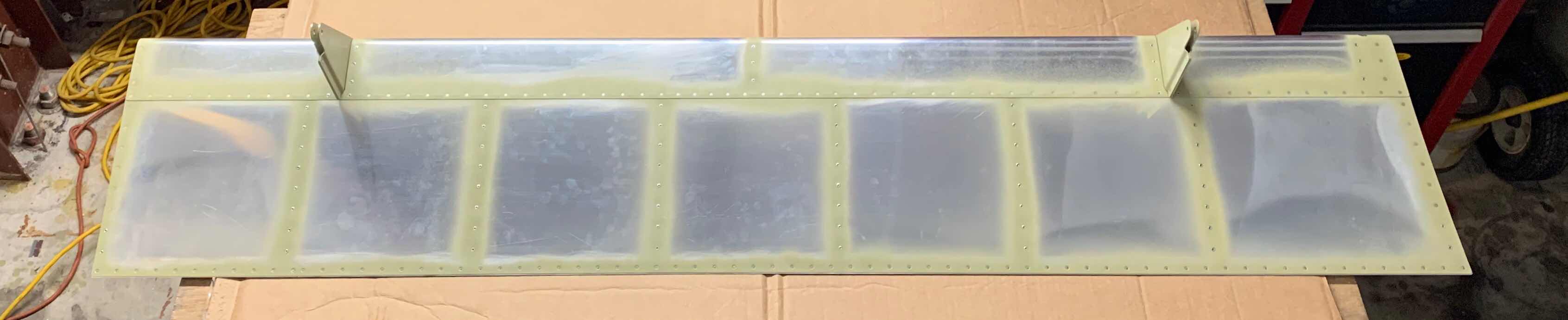
After I completed the work on the right Counterbalance today, I wasn’t completely happy with it. The plans want the Counterbalance to be flush with the outboard edge of the Nose Skin. The picture below shows the Left Aileron (completed in Part 6). You can see the Counterbalance is perfectly flush with the Nose Skin in the area circled.
Here is the Right Aileron.....not really happy with the result. In the circled area of the picture below, you can see that the Counterbalance is NOT exactly flush with the Nose Skin. How did this happen?
When I originally fit the Counterbalance to the Nose Skin, two #40 holes were match-drilled on either end of the Counterbalance with the Nose Skin. Eventually, the Counterbalance was removed from the Nose Skin for addition preparation steps. Then, the Counterbalance was reinstalled to make the remaining eight #40 match-drilled holes in the leading edge of the Nose Skin. My guess is I swapped ends on the Counterbalance when I reinstalled it for this step. So, the end of the Counterbalance you see in the picture above, should have been on the other end (or the outboard end).
I haven’t called Van’s regarding this mistake and I’m sure I could leave it this way and it wouldn’t cause any problems. However, it’s not right. I’ve said it before and I’ll say it again....I’m not going to build a PERFECT airplane, but I can get it as close to RIGHT as possible. So, following that philosophy, I ordered a new Counterbalance and Nose Skin from Van’s.
Another day off preparing the Stiffeners. I was able to complete the remaining 18 Stiffeners, so all 32 are now prepared. The only remaining steps are to treat them with Alumiprep, Alodine, and Akzo Primer. After that, they are riveted to Top and Bottom Ailerons Skin.....more on that later.
NO exciting work in the hangar tonight.....but, a necessary evil. I completed the preparaton of 14 of the 32 A-710 Stiffeners. I’ll work on the remaining Stiffeners again tomorrow.
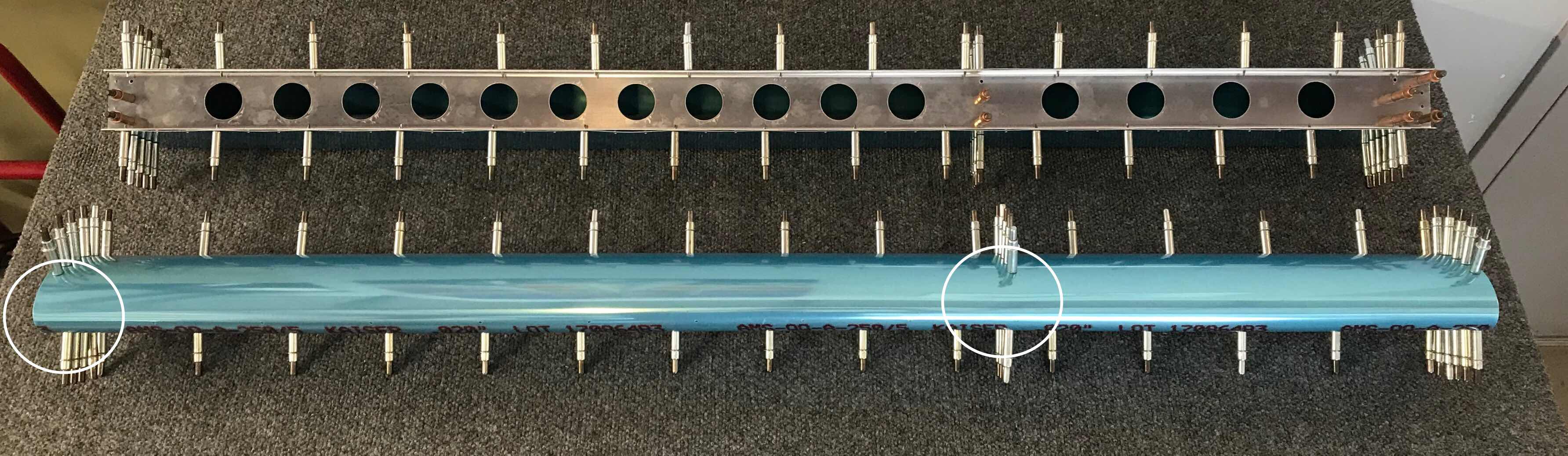
Today’s session was kind of long and I got a lot of work accomplished. To begin, I clecoed the Inboard Nose Rib, Doubler, and two Nose Ribs to the Spar as shown below. (The left Aileron is on the top and the right Aileron is on the bottom). The next step is to cut a length of ST304-065x1.375 Steel Tube to 34.625 inches. These Steel Tubes will serve as the Aileron Counterbalances. I found the the two Steel Tubes supplied by Van’s (also in the picture below) were almost exactly the correct length. Each Tube was about 1/32” short.....which won’t be a problem.
Next, the Nose Skin was clecoed to the lower Spar Flange and the Counterbalance was layed into the Nose Skin so its edge was aligned with the outboard edge of the Nose Skin. The Nose Skin was then clecoed to the upper flange of the Spar and all the Nose Ribs. This essentially “trapped” the Counterbalance between the inside of the Nose Skin and the two Nose Ribs. The picture below shows the Left and Right Ailerons clecoed together as described above. There were two #40 holes that had to be drilled in the locations of the two white circles. The holes were match-drilled from the Nose Skin into the Counterbalance.....using the Nose Skin hole as a drill guide.
Once those two #40 holes were drilled, the Spar was removed exposing the Counterbalance on the inside of the Skin. Here you can see how the Counterbalance was “trapped” as I described above.
The next step seemed difficult at first while reading the plans, but turned out to be rather easy. The two lower holes of the Nose Ribs had to be match-drilled #40 into the Counterbalance and clecoed. I used a 6” #40 drill bit, inserted through one of the Spar attach holes, to reach the lower hole of the Inboard Nose Rib as shown in the first picture below.....and then clecoed in the second. Additionally, I marked the location of the upper Nose Rib hole on the Counterbalance for later drilling.
I followed the same procedure for the Outboard Nose Rib.....6” #40 drill bit through one of the Spar attach holes, then clecoed, then marked the upper hole. I completed this process two times.....once for the Left Aileron and once for the Right Aileron.
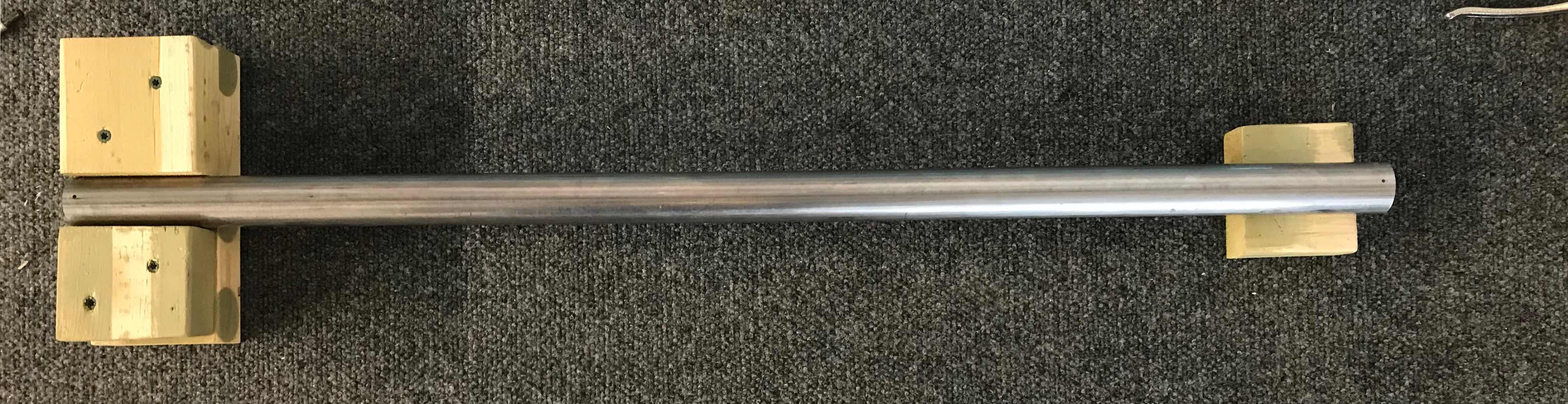
The Counterbalance was then removed from the Nose Skin. The two #40 match-drilled holes in the lower tabs of the Nose Ribs were final-drilled to #27 and the two marked holes in upper tabs were first match-drilled to #40 and then final-drilled to #27. To keep the Counterbalance from rolling while I was drilling the holes, I made this “holder” to keep it still. It worked great. The four tabs in the Nose Ribs were also final-drilled to #27.
Once the four holes were final-drilled to #27, the Counterbalance was attached to the Nose Ribs using AN526C632R8 screws and AN365-632A nuts as shown below. Here is the Inboard Nose Rib.....
.....and the Outboard Nose Rib.
You will definitely need something like these two little guys to get the job done....it’s pretty tight inside the Counterbalance.
Now, everything gets clecoed back together like in the second picture above. There are 10 holes in the leading edge of the Nose Skin that need to be match-drilled into the Counterbalance (the two holes on either end were previously match-drilled). The 10 holes are located in the white box in the picture below. Initially, the holes were match-drilled #40 using the holes in the Nose Skin as a drill guide. Then, the same 10 holes were final-drilled to #30. After each hole was drilled, a cleco was installed to keep the Counterbalance from being pushed away from the Nose Skin while being drilled. Eventually, LP4-3 blind rivets will be installed in these 10 holes.
That’s it for this session.....lots of work accomplished today.
I spent most of the today’s session Akzo Priming all the parts that were treated with Alumiprep and Alodine yesterday. Pictured below are the Inboard and Outboard Hinge Bracket to Nose Rib assemblies after being Akzo Primed and riveted together. The two assemblies on the top are the Outboard Hinge Brackets and the two assemblies on the bottom are the Inboard Hinge Brackets. All four of the assemblies are held together with AN426AD4-4 rivets, except for the four AN426AD3-4 that attach the two MS21055-L3 nutplates on the Inboard Hinge Brackets.
While the second batch of parts were drying, I continued work on the A-710 Stiffeners. I removed the blue protective coating and began preparing the Stiffeners as described in the excerpt below.
In the group of Stiffeners below, you can see the two on the bottom left have been trimmed and prepared. I used the one named “The Man” as a template for the remaining Stiffeners. If you look closely, you can see the blue sharpie marker outlining where the remaining Stiffeners will be trimmed. It’s going to take awhile to complete all of these Stiffeners.
After the second batch of parts dried, I clecoed the Main Ribs to the Inboard Hinge Brackets.....
.....and the Main Ribs to the Outboard Hinge Brackets.
During the next session, I will rivet these two assemblies together and continuing preparing the Stiffeners.
After prepping many parts yesterday, I started today’s session by treating them all with Alumiprep and Alodine. All of these parts are shown hanging up to dry in the picture below. I plan on Akzo Priming all of these parts during tomorrow’s session.
The next few steps in the plans have you rivet several of the pieces together that were just treated above. I also want to Akzo prime them before assembly. So, I moved on to a few steps further in the plans. I went several steps ahead to work on and separate the A-710 Stiffeners. Here is how they come from Van’s.....
.....and after I separated them. After separated, the holes in the Flanges were final-drilled to #40. There are 32 of these Stiffeners to prepare, so I imagine the work on these will be covered over the course of several work session. I will continue working on them during the next session.
The next step is to separate The A-1008-1 Doubler. Here is the Doubler separated into two pieces or two Doublers.
The last step in preparation of the Doublers was to countersink the two inside holes for the head of a AN426AD3 rivet. Here is the finished product. These two Doubler were also treated with Alumiprep and Alodine during this session are are hanging up to dry in the first picture.
During the last session, I separated the Main Ribs. I started the prep process today. I removed the protective plastic and cleaned all the edges. After getting all the large burrs off with the 6” Scotchbrite Wheel (from where the pieces were connected), I found the easiest way for the finish sanding was to stick the sandpaper to the workbench and slide the pieces across the sandpaper instead of holding both pieces in my hands and sanding.
After cleaning the edges, the #40 holes were dimpled using my Substructure Dimple Diesand hand squeezer. The next step was to countersink the six holes on the two A-1006-1B Outboard Hinge Brackets as shown in the plans excerpt below. Now, here is a point of “confusion” for me. In the plans excerpt, it shows the six holes on the bottom of the A-1005-1R Main Rib being dimpled (120 degree). I’ve read the plans several times (maybe I just plain missed it), but I can’t find any mention of the dimpling of these holes in any of the steps in the plans. Earlier in the plans, the #40 holes (which are on the Flanges) are dimpled, but the holes I’m referencing here are #30. Anyway, I’m going to go ahead and dimple them as the illustration shows and go from there.
Here are the Main Ribs after being prepped (minus dimpling the #30 holes discussed above).
Lastly, the Inboard and Outboard Hinge Brackets were clecoed to their Main Ribs. I’ll pick it up from here during the next session.
In the previous session, all the Hinge Brackets for the Left and Right Aileron’s were separated and edge cleaned. Tonight, the Brackets will be “fitted” to their respective Nose Rib. The Outboard Hinge Brackets to Nose Ribs are the upper two Ribs in the picture below. The Inboard Hinge Brackets to Nose Ribs are the two Ribs in the bottom of the pictures. The two A-1004-1R and A-10041L Nose Ribs in the middle will be used to attach the Counterbalance. Initially, the #30 holes common to the Brackets and Ribs were final-drilled. Next, the holes in the Brackets (on the opposite side of the Ribs) were countersunk to accept the head of a AN426AD4 flush rivet. These pieces are now prepared and ready to riveted together. However, prior to doing that, I am going to a treat the parts with Alumiprep, Alodine, and Akzo Primer.
So, moving on. The next step in the plans is to separate the Main Ribs as shown below.....
The two A-1005-1L Main Ribs are shown on the right and the two A-1005-1R Main Ribs are shown on the left.....
.....and here they are separated. I used my cutoff wheel to separated the parts.
To start the session, I applied the 3M Adhesive Transfer Tape to the long and short Trailing Edge “V-Channels”.
Pictured below is the Bottom Skin and Trailing Edges clecoed into place on the Flap. The MK-319-BS blind rivets will be installed where the vertical rows of rivets are located. However, the two vertical rows of clecos on either end will have solid AN426AD3-3.5 installed in these locations. The Trailing Edge will accept AN426AD3-3.5 solid rivets.
Here are all the rivets installed in the Bottom Skin.....
.....and the Top Skin.
Earlier in this section, I cut the Trailing Edge “V-Channels” as instructed in the plans. However, I cut the ends just a little longer to match the ends with the Top and Bottom Skins. The picture below shows where I left the overlap on the V-Channel. (You can also see three of the rivets set in the Trailing Edge).
The two pictures below show the Inboard and Outboard edges after the V-Channels were sanded and made even with the Top and Bottom Skins.
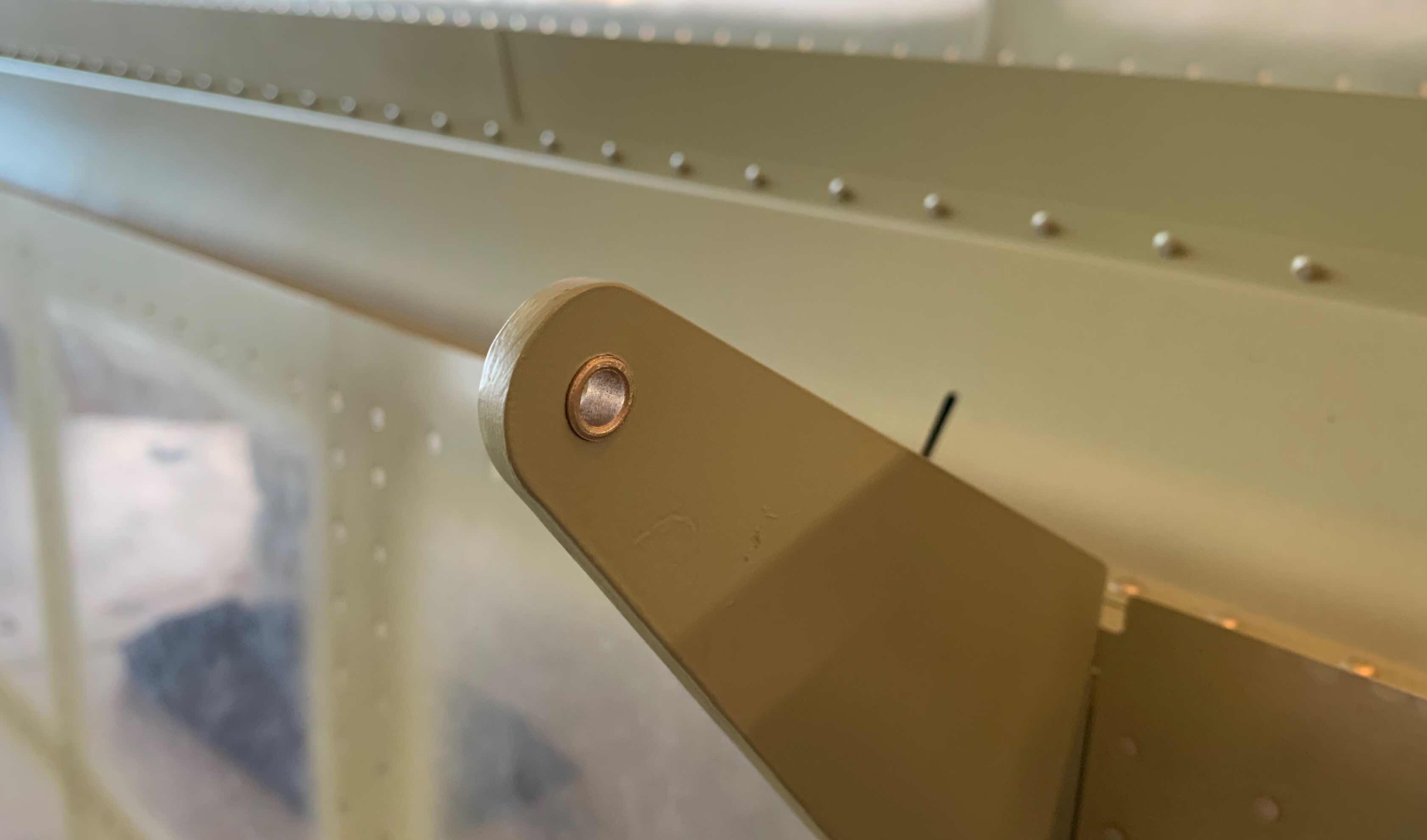
Lastly, the four bushing were pressed with a C-Clamp into their home on the Flap Hinge Brackets. Below is an example of two of them.