This blog was created to memorialize the building process of my Van's Aircraft RV-14 and to satisfy the requirements for certification in the Experimental Amateur Built Aircraft category. It will also serve as a central location for ME to reference in the future on processes and techniques I used during the build. Additionally, it will allow my family, friends, and other interested builders the opportunity to follow along during my build…..and might be helpful to someone along the way.
Today, I completed the remaining preparation and deburring work for all the parts of the Right Flap. After the previous couple of sessions, the Spar was the last piece that needed attention. You can’t really tell in the picture below, but all the parts have been prepared. These parts will get treated with Alumiprep, Alodine, and Akzo primer in the next few sessions.
After completing the Spar preparation, I started the process of countersinking the Trailing Edge V-Channel. I will provide more details of this process tomorrow when I complete the countersinking.
During the next session, I will finish countersinking the Trailing Edge “V-Channel” and dimple the Top, Bottom, and Nose Skins.
Again, not much to show during this session.....I continued to prepare and debur parts.....yea! I was able to complete the edge preparation and hole deburring for all the remaining parts below, except the Spar.
During the next session, I will finish preparing and deburring the Spar and start dimpling and countersinking.
Not much to show during this session. On Saturday, I showed the picture below containing all the parts for the Right Flap. I started deburring all of them today.
I completed about half of the parts, and will continue deburring during the next session.
I finished yesterday’s session by clecoing the whole Right Flap assembly together. This was done so several holes could be match and final-drilled. I started today by match-drilling #40 the FL-1004-L & -R Nose Ribs using the FL-00001-R Nose Skin as a guide. The plans excerpt below shows the example locations at the top.
The next step was to final-drill #40 the Trailing Edge. The plans have a note that says, “when drilling the trailing edge, drill perpendicular (90 degrees) to the centerline of the trailing edge extrusion, not perpendicular to the surface of the Top Skin”. In the plans excerpt below, it shows the angle between the drill bit and the Top Skin to be 84 degrees and the desired 90 degree angle between the drill bit and the Trailing Edge centerline. I came up with a really scientific method for drilling the proper angle.....I used my eyeballs. I compared the angle between the drill bit and the cleco next to the hole being drilled. After drilling the hole, I inserted a 6” #40 drill bit into the hole and compared the angle between that drill bit and the centerline of the Trailing Edge. The scientific method of using my eyeball says the angle is very close. I also used this method for the Left Flap and it worked out okay.
The last parts to get match-drilled are the Hinge Brackets. The plans instruct you to install the appropriate hardware as shown in the white circle below. There are four holes that need to be match-drilled as shown on the Outboard Hinge Bracket below. In conjunction with the hardware, I installed cleco clamps between the holes to hold the assembly tight and in place to be drilled. I used my pneumatic drill with a #40 bit to drill the holes.
I completed the same process on the Inboard Hinge Bracket below.
Finally, after all the match and final-drilling was complete, everything had to be disassembled. Here are all the pieces that make up the Right Flap. In the next session(s), I will have to debur and dimple many holes and countersink the Trailing Edge “V-Channel”.
With the Left Flap complete, guess what I did....moved on to the Right Flap.
Minus the Skins and the “V-Channel”, here are all the parts that will make up the Right Flap. This process is a mirror image of the Left, so it should go fairly quickly.....I hope! Most of these parts were already prepared when I competed the Left Flap, so again, this assembly should go a little faster.
The first step in today’s session was to cleco the Nose Ribs, Main Ribs, Modified Main Rib, Rod End Rib, and Hinge Pair subassemblies to the Spar. All of that was completed and here are two pictures of what it looks like.
The next step was to prepare the Trailing Edge. Here is the excerpt from the plans describing how.
Here is what my completed “junction” of the two Trailing Edges looks like.
I trimmed the outboard edge, but left a little extra until later. After all the double flush rivets are set in the Trailing Edge, I will sand this area to match the Top and Bottom Skins.....just like I did for the Left Flap.
I trimmed the inboard edge in the same fashion and will finish it when I finish the outboard edge.
Here are ALL the pieces clecoed to together. The order of assembly was:
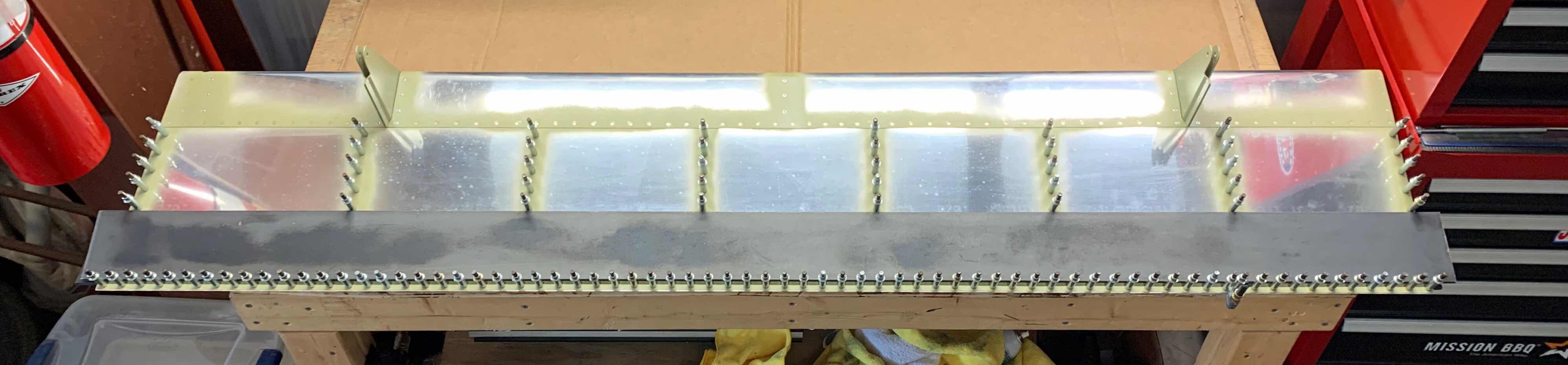
After yesterday’s session, the last remaining step to complete the assembly of the Left Flap is to rivet the Trailing Edge. To set this up, here is how I “stacked” my work area for the rivet installation:
1. Put one of the 6’ backriveting plates on the workbench (for a flat surface and as the backriveting plate)
2. Placed the Left Flap on top of it
3. Put the other 6’ backriveting plate on top of the Flap (for its weight: also added additional weight to keep the Flap as straight as possible)
4. Clamped the top backriveting plate to the Flap with a spring clamp (to keep it from moving during the riveting process)
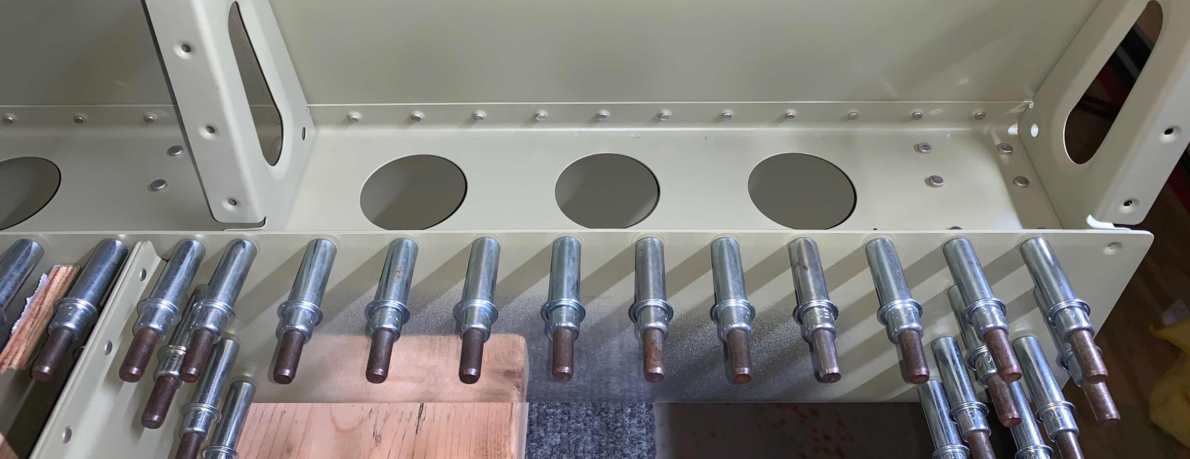
All 71 AN426AD3-3.5 will be double flush with the manufactured head on the Top Skin. The first picture below shows six of the rivets. The first three on the left have already been set are “double flush”. The three rivets on the right are waiting to be set. This is a cool perspective of the before and after.
This picture is just a larger view of the one above.
Because of the angle created at the trailing edge of the Flap, the rivets are not “square” to the Bottom Skin (you can see that in the first picture above). In order to set the double flush side “square” to the Bottom Skin.....you initially have to set the rivet with a few taps and then angle the rivet gun (to the Bottom Skin angle) to make the double flush side (shop head) square to the Bottom Skin. The video below shows how I did it. The plans say to squeeze these rivets, but I decided to set them as shown below. I felt pretty comfortable doing it this way and I’m pleased with the results. The trailing edge turned out to be pretty darn straight.
Once all 71 rivets on the trailing edge were set, the last step was to trim/file/sand the trailing edge “V-Channel” flush with the Top and Bottom Skins. The picture below shows the completed outboard edge.....
.....and this picture shows the completed inboard edge.
I stopped yesterday’s session because I needed a 6” #33 drill bit for the eight holes on either side of the Hinge Bracket. I picked up three 6” #33 drill bits from Pan American Tools because as the old saying goes.....one is none and two is one (I added one more for good measure). I final-drilled the 16 holes (eight on each Hinge Bracket) and pulled the MK-319-BS rivets as shown in the two pictures below.
Just for comparison purposes, I took this photo of the inside (or shop head side) of the rivets. The two aft most MK-319-BS rivets (the ones through the Spar) are circled in black. The rivets to the left and above these are the solid rivets.
Once those 16 rivets were taken care of, it was time to move on to the Trailing Edge (“V-Channel” as I like to call it). Just like on the Rudder and Elevators, I will use the 3M F9460PC Adhesive Transfer Tape(recommend by Van’s) for my bonding material. The picture below shows the tape after being applied to the two “V-Channels”.
I decided I wanted a back riveting plate longer than the trailing edge of the Flap. So, I went to my local metal shop and picked up two 6’ “back riveting” plates. Below you can see the smaller 8” Back Riveting Plate I purchased from Cleaveland Aircraft Tool and one of the two 6’ plates I purchased. Each one of the plates was around $28 dollars and I suspect they will be useful for many different applications.
After I applied the 3M Adhesive Tape as shown above, it was time to install the “V-Channels” between the Top and Bottom Skins. Initially, I positioned the tape in the proper location on the Top Skin (easier for me to see the dimpled Skin and countersunk “V-Channel” line up). Then, I pulled the backing off the tape, as shown below, and installed a cleco into every rivet hole.
The plans now say to let the adhesive cure before moving on to the installation of the rivets. The plans also recommend adding weight to the Bottom Skin to keep the Flap flat while the adhesive is curing. So, I put one of the 6’ back riveting plates under the trailing edge and one of top of the trailing edge as shown below. Additionally, I added clecos to every hole on the Bottom Skin.
After the 3M Adhesive Tape cured, it was time to install the remaining MK-319-BS blind rivets in the Bottom Skin. Here are eight of the blind rivets installed on the Bottom Skin. Additionally, there is one lonely little blind rivet that gets installed in the white circle in the bottom right corner of the picture. There is not enough room on the backside of the rivet location to get a squeezer yoke or a bucking bar into to set a solid rivet.....this is the reason the blind rivet is required here.
Here is a quick video of the single MK-319-BS rivet being set.
Here are 16 more of the blind rivets after being set.....
.....and the last eight.
With the exception of the single blind rivet in the aft most Skin to Rib location, the inboard and outboard Skin to Ribs use AN426AD3-3.5 rivets.
During the last session, many solid rivets were installed in the Top Skin. During today’s session, more solid rivets and blind rivets will be installed in the Nose Skin. Here is the leading edge Nose Skin above the Outboard Hinge Bracket. This rivet location uses eight MK-319-BS blind rivets as shown in the black box. The leading edge Nose Skin above the Inboard Hinge Bracket was also installed.
The inboard end of the Flap uses both solid (AN426AD3-3.5) and blind (MK-319-BS) rivets. Just as above, the holes receiving the blind rivets had to be final-drilled to #33 prior to installing the rivets. Here is the top side of the inboard end of the Flaps and you can see the four blind rivets on the left and the solid rivets on the right.
This is the bottom side of the inboard end of the Flap (opposite side from above). This side receives the same rivets as the top, but only three of each rivets are used.
This is the inboard side of the Flap. This shows the Nose Rib with the solid rivets installed (next to the blind rivets above) on the Nose Skin to Rib Flanges.
The outboard end of the Flap only receives solid rivets (blind rivets were only installed on the inboard side). Here are the seven rivets installed on the Nose Skin to Nose Rib.
I have to stop here for the day. Prior to setting the MK-319-BS rivets, the holes have to be final-drilled to a #33. I have #33 drill bits, but in standard length bits. So, I will need at least a 6” bit to clear the Hinge Brackets. Below are the two Hinge Bracket locations
To get started on today’s session, the two most aft rivets of the Skin to Ribs are not riveted yet. So, to make sure I didn’t......I put some orange tape on the clecos.
During this session, 107 rivets were installed. Here is an example of some of the installed rivets. All the rivets on the Skin to Spar are complete and the first five rivets (forward to aft) on the Skin to Ribs are complete.
The outboard end of the Top Skin.....
.....and inboard end of the Top Skin.
The next three photos show the inside of the Flap with the rivets set on the Spar.
Obviously, the first step is to cleco all the pieces together. To begin with:
1. The FL-00001-L Nose Skin was slid over the two Hinge Pair Subassemblies of the skeleton and clecoed to the bottom of the FL-00003-L Spar
2. Next, the Flap assembly was then put into the cradles and the FL-00002A-L Top Skin was slid in between the Spar and Nose Skin
3. Lastly, the Skins and clecoed to the skeleton.
Here is a view of the bottom of the Flap.....
.....and the top of the Flap.
Here is a closer picture of the internal area of inboard side of the Flap with the clecos installed. In this view, you can also see the aft portion of the Top Skin that was not primed. Again, this is where the trailing edge “v-channel” will be installed later in the build.
Pictured below is the “skeleton” for the Left Flap. I started by clecoing the whole assembly together and then installed the rivets. All of the rivets used for this assembly were AN470AD4-4 universal rivets. The two pictures below show a couple angles of the completed “skeleton”. The next step is to install the Top, Bottom, and Nose Skins.
Now, going back to installing the rivets in the “skeleton” above. I’ve seen on other builder’s installing these rivets with hand squeezers, but found it was kind of a pain. The rivets on either end of the assembly were very easy to set with a hand squeezer, but the other one’s.....not so much (for me anyway). Initially, I tried using the rivet gun with a 1/8 Double Offset Cup Rivet Setand bucking bar. This mostly worked okay, but I ended up having to drill out a few rivets due to putting “smilies” on them and I wasn’t overall happy with the results.
So, I decided to come up with another plan. Here is one of the steel bucking bars I have.
I drilled two #12 holes in the two corners of the fattest part as shown below. I then used my belt sander to make sure the surface would allow the rivet set to sit flush on the bucking bar.
Once that was complete, I installed the rivet set into the top hole.....
.....and bottom hole to check the fit. I had to drill each hole a little deeper due to the shank on the rivet set, but it otherwise fit like I wanted.
Here is an example of how it was used. Because the bar was long and heavy, it provided plenty of “bucking authority” on the rivet. I used the rivet gun with a flat set to backset the rivets. It worked perfectly. I wish I would have come up with this idea several months ago when I was installing the Ribs to the Wing’s Main Spar. Anyway, I have it now and it works perfectly.