Showing posts with label Section 11-Empennage Attach. Show all posts

Sunday, November 5, 2017

Empennage, Attach (Part 3)

I have also made the decision to postpone work on the Empennage Attach section.  Roger and I have started the process with two sessions, but with the delivery of the Wing Kit, I wanted to get to work on it.  

The plans say the Elevators, Rudder, Rudder Cables, Horizontal and Vetical Stabilizers can be final installed any time during the building process.  

Tuesday, October 31, 2017

Empennage, Attach (Part 2)

We picked up today where we left off yesterday.  The plans say to secure the Elevator in the “trail” position by placing strips of duct tape over the gap between the Elevator Counterbalance Arm and the Horizontal Stabilizer.  Instead of using duct tape, I decided to use the clamp you see in the picture below.

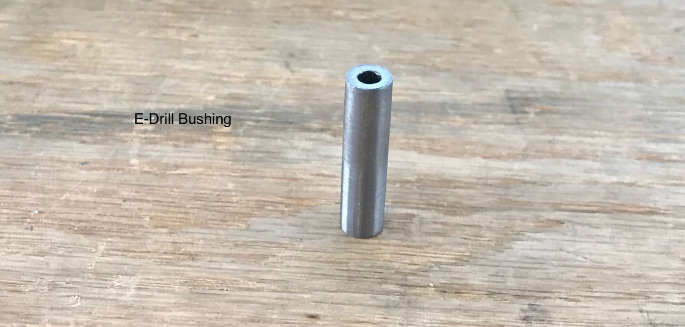
The excerpt below shows a couple of pieces that need to be prepared.  The first is the wooden (or plastic) Elevator Spacer you need to fabricate.  The spacer will go between the Inboard Hinge Bracket and the Elevator Horn and is designed to prevent any flexing during the drilling process.  The second piece needing attention is the E-Drill Bushing.  It will be inserted into the Flange Bearing to ensure a perfectly straight hole is drilled into the Left Elevator Horn (and then later the Right).


Below is the actual E-Drill Bushing supplied with the kit.  The bushing was a little larger than the hole in the Flange Bearing.  So, following the directions in the plans, I put the Busing in a drill press and used 220 grit sandpaper to grind the diameter down while it was spinning.  This process worked great and was very easy.  

Here is the Busing inserted into the Flange Bearing.  Now, the Hinge Bracket and Elevator Horn need to be clamped “lightly” together.  The last step before removing the Left Elevator (and going through the same process on the Right Elevator) is to drill a #30 pilot hole into the Elevator Horn using the E-Drill Bushing as a drill guide.  This #30 hole will ultimately be enlarged to a 1/4” using a step drill. 

I will continue from here tomorrow.....the Wing Kit just arrived!

Monday, October 30, 2017

Empennage, Attach (Part 1)

My stepdad is back in town for a few weeks to help me with the build.  So, we went to work and started a new section.....the Empennage Attach.  All of these parts are coming together and starting to look like an airplane.....it’s gonna be so fast!


This section starts off by installing the MD3614M Rod End Bearings (x4) and  AN316-6R Jam Nuts (x4) into the Left and Right Elevators and shown in the picture below.


This is an example of one of the Rod End Bearings installed in the Right Elevator. 

The next step is to use an electronic level to verify the freedom of Elevator travel.  According to the plans, the “Full Up” Position will be 30.0 degrees (+0.00, -0.5) and the “Full Down” Position will be 25.0 degrees (+0.00, -0.5).  Here is the excerpt from the plans showing how this should look.  

The plans also tell you that the Elevator should not come in contact with the flanges of the upper or lower Horizontal Stabilizer in the full up or full down position.  Based on the calculations from my electronic level, my Elevator does not make contact.  I did, however, have slight rubbing on the rolled leading edges of the Elevator.  I gently massaged the area that was rubbing....no more rubbing.