This blog was created to memorialize the building process of my Van's Aircraft RV-14 and to satisfy the requirements for certification in the Experimental Amateur Built Aircraft category. It will also serve as a central location for ME to reference in the future on processes and techniques I used during the build. Additionally, it will allow my family, friends, and other interested builders the opportunity to follow along during my build…..and might be helpful to someone along the way.
Roger and I started the Wing Kit inventory after it was delivered this afternoon. This kit has two crates.....one for the Spars (and other long pieces) and one for everything else. I completed the Empennage inventory by myself back in February, but this inventory went MUCH faster when you have 100% more help!
We picked up today where we left off yesterday. The plans say to secure the Elevator in the “trail” position by placing strips of duct tape over the gap between the Elevator Counterbalance Arm and the Horizontal Stabilizer. Instead of using duct tape, I decided to use the clamp you see in the picture below.
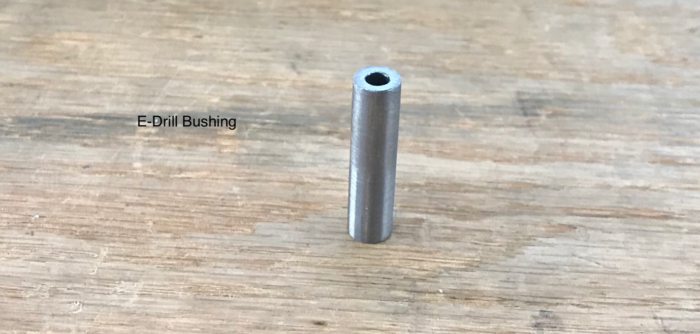
The excerpt below shows a couple of pieces that need to be prepared. The first is the wooden (or plastic) Elevator Spacer you need to fabricate. The spacer will go between the Inboard Hinge Bracket and the Elevator Horn and is designed to prevent any flexing during the drilling process. The second piece needing attention is the E-Drill Bushing. It will be inserted into the Flange Bearing to ensure a perfectly straight hole is drilled into the Left Elevator Horn (and then later the Right).
Below is the actual E-Drill Bushing supplied with the kit. The bushing was a little larger than the hole in the Flange Bearing. So, following the directions in the plans, I put the Busing in a drill press and used 220 grit sandpaper to grind the diameter down while it was spinning. This process worked great and was very easy.
Here is the Busing inserted into the Flange Bearing. Now, the Hinge Bracket and Elevator Horn need to be clamped “lightly” together. The last step before removing the Left Elevator (and going through the same process on the Right Elevator) is to drill a #30 pilot hole into the Elevator Horn using the E-Drill Bushing as a drill guide. This #30 hole will ultimately be enlarged to a 1/4” using a step drill.
I will continue from here tomorrow.....the Wing Kit just arrived!
My Wing Kit crates arrived today with NO DAMAGE!!!!! This is my fourth delivery from Van’s over the course of my build. The first three shipments were damaged (two by FedEx and one by Old Dominion), but this one from ABF was in great condition. Additionally, working with the company was a pleasure. The crates were delivered a day early (my request), the driver called prior to delivery (like they are supposed to), and was a very nice guy.
MAYBE customer service is not totally dead! Hopefully I just found my preferred shipper.
My stepdad is back in town for a few weeks to help me with the build. So, we went to work and started a new section.....the Empennage Attach. All of these parts are coming together and starting to look like an airplane.....it’s gonna be so fast!
This section starts off by installing the MD3614M Rod End Bearings (x4) and AN316-6R Jam Nuts (x4) into the Left and Right Elevators and shown in the picture below.
This is an example of one of the Rod End Bearings installed in the Right Elevator.
The next step is to use an electronic level to verify the freedom of Elevator travel. According to the plans, the “Full Up” Position will be 30.0 degrees (+0.00, -0.5) and the “Full Down” Position will be 25.0 degrees (+0.00, -0.5). Here is the excerpt from the plans showing how this should look.
The plans also tell you that the Elevator should not come in contact with the flanges of the upper or lower Horizontal Stabilizer in the full up or full down position. Based on the calculations from my electronic level, my Elevator does not make contact. I did, however, have slight rubbing on the rolled leading edges of the Elevator. I gently massaged the area that was rubbing....no more rubbing.
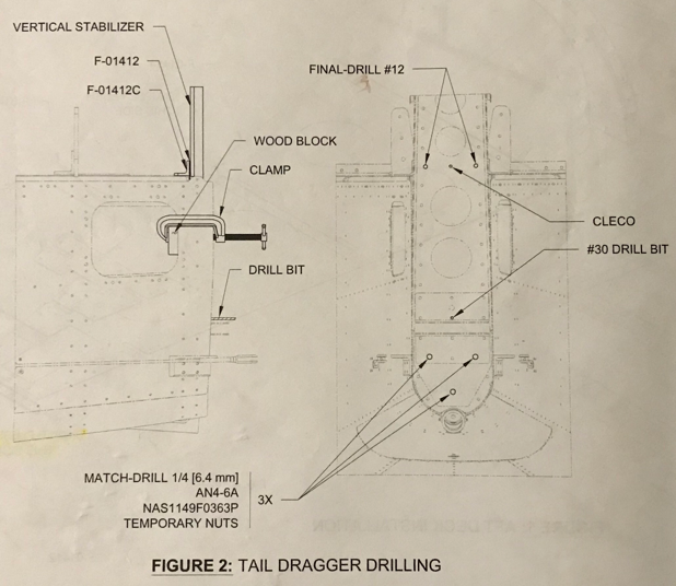
After completing the “new” Vertical Stabilizer, the next step was to Match-Drill and Final-Drive the APPROPRIATE hole locations to attach it to the Aft Fuselage. If you follow my blog, you know this is where the train came off the tracks and I made a bone head mistake a few weeks ago. Here is where the holes are supposed to go.....and I followed the directions this time! You have no idea how many times I checked this step.....again and again and again!
I wasn’t able to publish this post prior to midnight, so this work session was actually completed on Saturday, October 28, 2017.
I primed the Rear Spar and Rear Spar Doubler on Friday night and let it dry overnight. To complete the new Spar on Saturday, I riveted the Rear Spar, Spar Doubler and Hinge Brackets using the hardware called out in the plans. The three pictures below show the completed Vertical Stabilizer with the newly completed Spar Assembly.....minus the errant hole!!!!!
I did make one change from the “first Spar” to the “second Spar”. The build plans call for AN426AD3-3.5 rivets to be used to attach the Skin and the Rear Spar (which is what I used on the first Spar). However, I used AN426AD3-4 rivets on the second Spar. I used a rivet guage and measured both rivets. The AD3-3.5 rivets measured just a little short and the AD3-4 measure just a little long. I set one of the AD3-4 rivets and liked the result much better than the shorter ones. So, I used them on the rest of the assembly. Very pleased with the outcome.
I haven’t had the most desirable conditions to prime the Spar and Spar Doubler, so to keep moving forward.....I began removing the “bad Spar”. The picture below shows the Vertical Stabilizer with the Spar/Spar Doubler attached.
This is the same Vertical Stabilizer after the 72 rivets (64 AN426AD3-3.5, two AN470AD4-4, three AN470AD4-6, and three LP4-3 rivets) were removed. And guess what.....I didn’t damage any of the holes!! That’s a victory right??
Over the next day or so, I will prime the Spar/Spar Doubler, rivet the two pieces together, and install it on the Verical Stabilizer.
Well, from reading my previous posts, you know I put a hole where it didn’t belong. I received great advice from the big brains on the Van’s Airforce Forums and from Van’s Aircraft on how to “fix” my problem. However, like one previous time before, I feel like it’s a bandaid fix for a bonehead mistake I made! So, after much deliberation, I decided to rebuild the Vertical Stabilizer Spar and “get rid” of my problem. I ordered the replacement parts from Van’s and they are shown below.
I re-ordered the VS-803PP Rear Spar, VS-410, 411, 412 Hinge Brackets, VS-808PP Rear Spar Doubler, and the F-01412 A & B Bulkheads. At this point, I am definitely going to rebuild the Rear Spar Assembly, but I haven’t made a decision regarding the Bulkheads (two pieces on the bottom).
So, let’s begin.....
I started by Final-Drilling #12 the six Rudder attach holes in the Hinge Brackets. Then, the whole Spar Assembly was clecoed together, the Hinge Brackets were Final-Drilled #30, the Rear Spar and Spar Doubler were Final-Drilled to #30, and two holes were Match-Drilled #30 from the Spar/Spar Doubler to the upper Hinge Bracket off the VS-410PP (lower assembly, upper bracket).
Finally, I disassembled all parts and deburred.....including the appropriate edge work. The next step was to dimple the Rear Spar to accept a dimpled Skin. Just like on the previous build, I used the Substructre Dimple Dies for this part.
The next piece of work was to Machine Countersink the #30 holes in the Rear Spar Doubler that attach the Rear Spar to the Doubler and dimple the corresponding #30 holes in the Rear Spar. This area will be joined together with AN426 flush head rivets and ultimately attach to the Rear Fuselage.
Finally, I gave both pieces a bath with Alumiprep and Alodine and hung them up to dry. I will prime and assemble the two pieces tomorrow. This picture shows the Rear Spar Doubler after getting the #30 countersinks, Alumiprep, and Alodine. It’s hanging up to dry with the Rear Spar.
As I’ve mentioned in other posts, I decided to use the optional flush screw installation on the Access Panel Cover Plates. I dimpled the eight holes in the plate below with #6 screw dimple dies. I have not yet treated the Cover Plates with Alumiprep, Alodine, or Epoxy Primer. I will do so in the next few days.
This is the left side of the fuselage with the Cover Plate attached. Eight AN507-632R8 screws are used to hold the Cover Plate in place.
This is the right side Cover Plate. The same hardware is also used on this side.
My buddy Frank helped me finish up riveting the F-01475 Top Skin. We shot all the remaining rivets between the Top Skin and Left/Right Top Side Skins. This picture is looking forward.....
This picture is looking aft.....
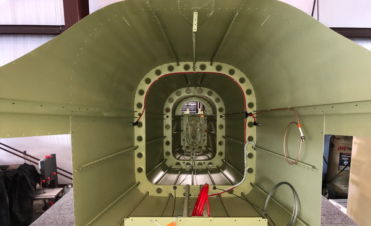
This is the inside of the Aft Fuselage looking aft. The two rows of rivets we set today are the ones on the left and right side of center.
This is the looking aft inside the entire Aft Fuselage assembly. I just thought this was a cool picture.....
The three last remaining rivets in the Aft Fuselage are the ones circled below. These rivets connect the F-14131 Upper Aft Fuselage Rib to the F-01407 Bulkhead. I was able to set the bottom rivet with the hand squeezer, but don’t have the reach for the top ones. I also tried the pneumatic squeezer, but the bottom was to big. So, I guess I’m going to have to shot these two with the rivet gun and bucking bar.
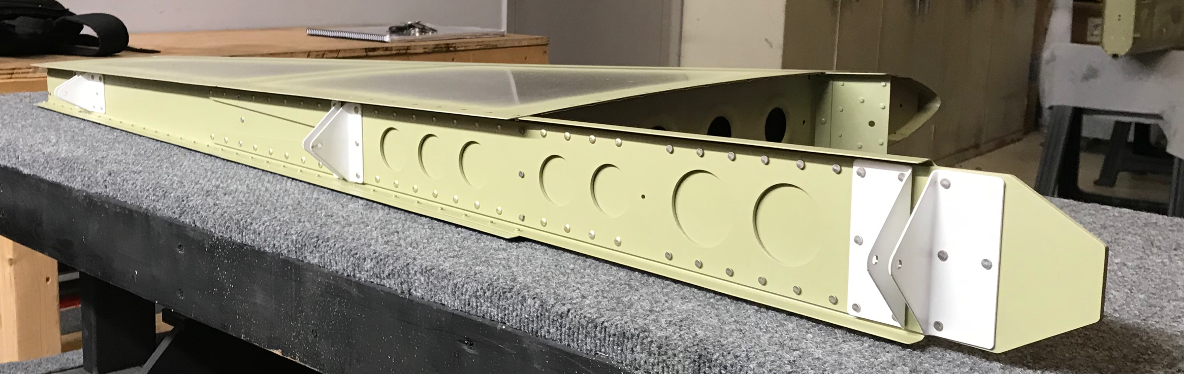
It only took a short session tonight to finish riveting the right Top Side Skin. My buddy Jeff helped me shoot the last 44 rivets and it went pretty quickly. The clecos you see on the side are locations that do not get rivets during this section of the build. The Aft Fuselage assembly will be joined to the Fuselage in the future and be riveted at that time. In the three photos below, I’ve attached the Top Skin to the Aft Fuselage. The Top Skin is now ready for riveting, but I will have to wait for a second set of hands to set the last 118 rivets. Once those rivets are set, the Aft Fuselage section will be complete!
Below is an excerpt from the plans dealing with the attachment holes for the Vertical Stabilizer. Since I am building the tailwheel model, there are five bolts that hold the Vetical Stabilizer to the Aft Fuselage assembly. There are two #12 holes at the top and three 1/4” holes in the bottom.
Alright.....I’m having to play a little catchup here. I didn’t get a chance to post for several days, but was still doing work on the plane. I’m going to catch up here as best as I can.