Friday, July 19, 2019

Fuselage, MID Lower Structure (Part 31)

With the Step Attach Assemblies completed and riveted the F-01405 Bulkhead, it’s now time to install the remaining Baggage Ribs.

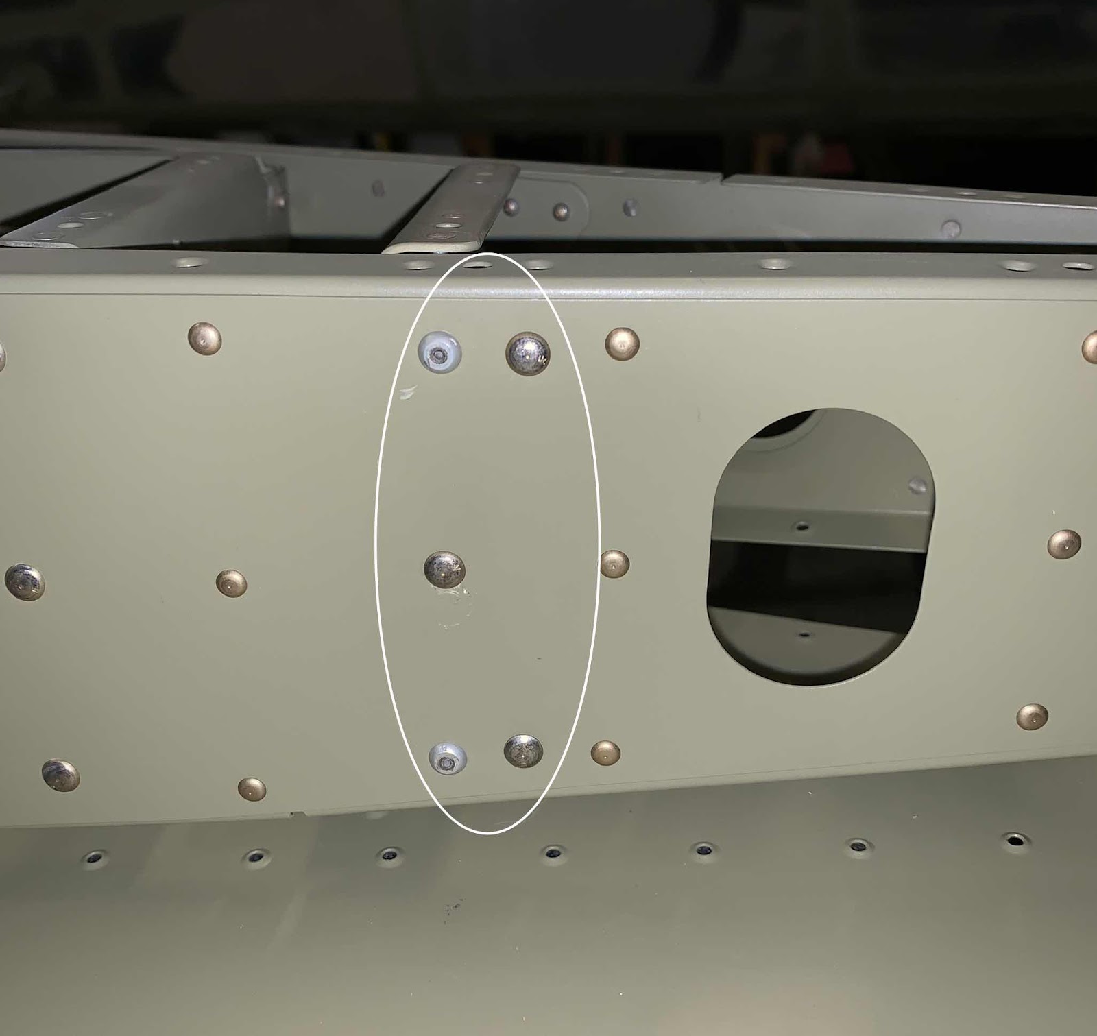
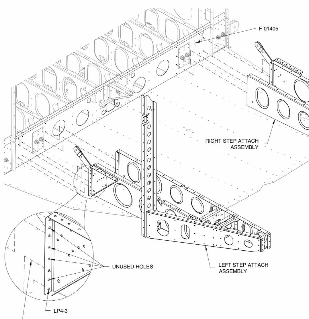
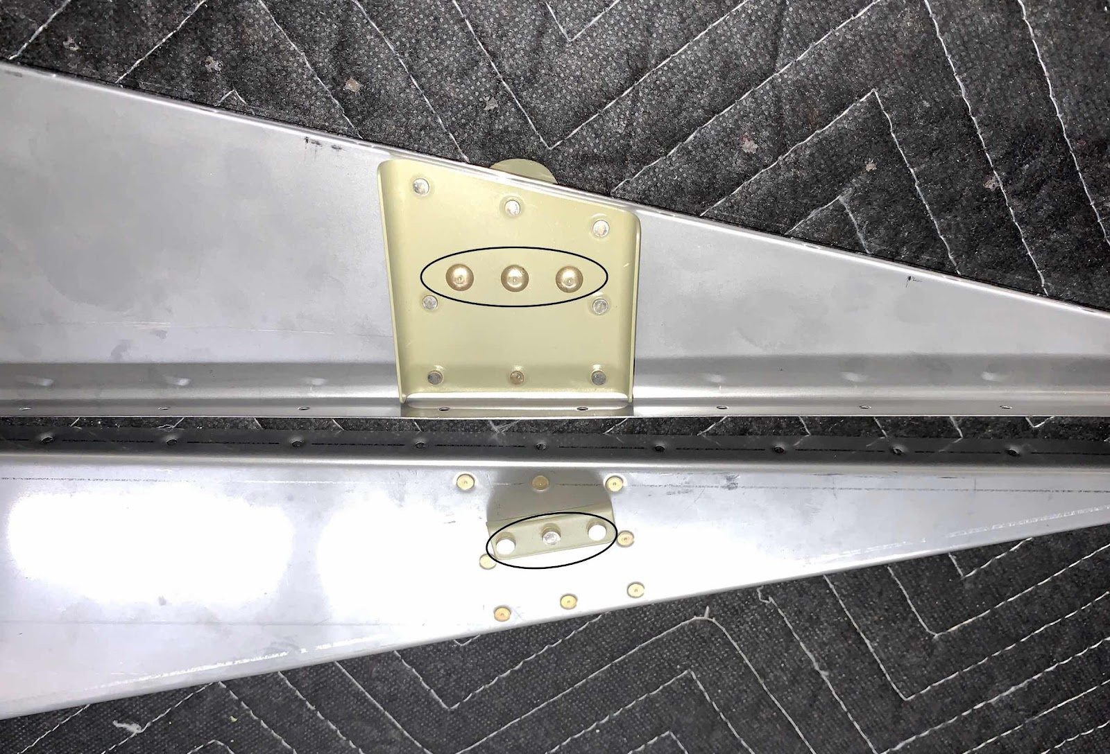
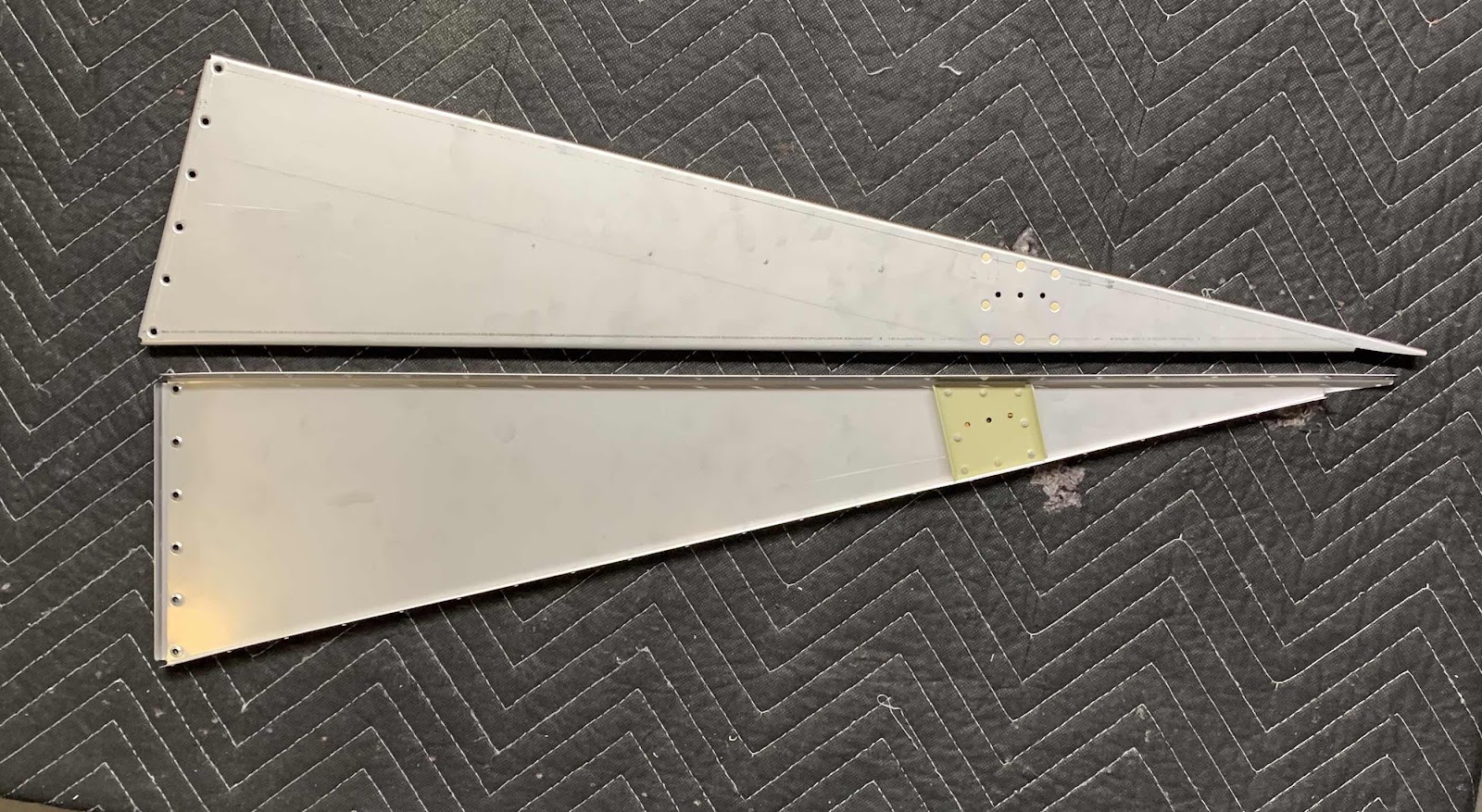
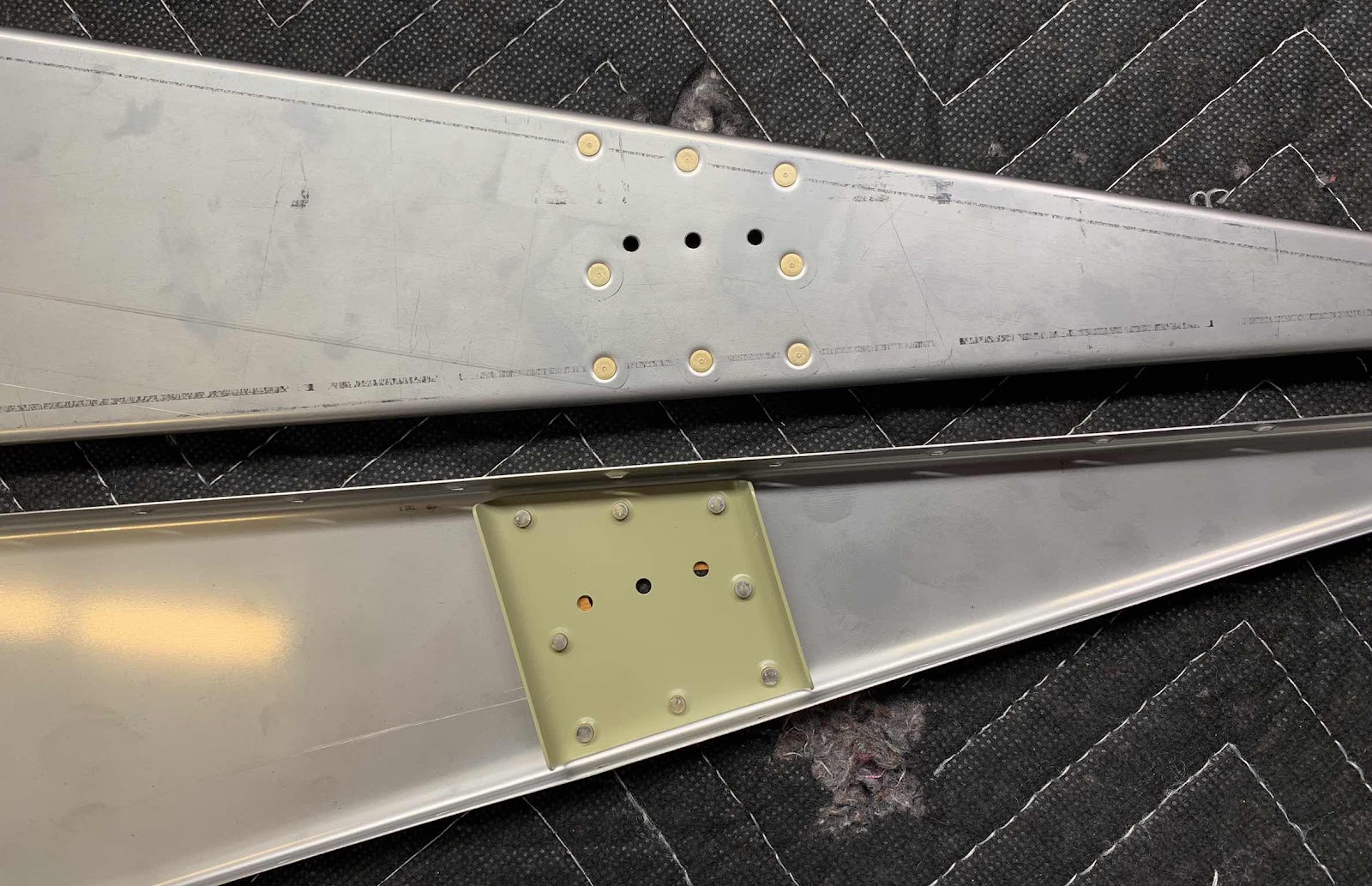
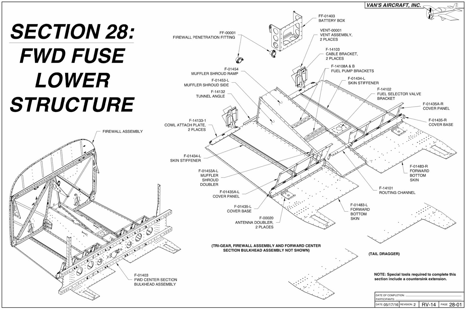
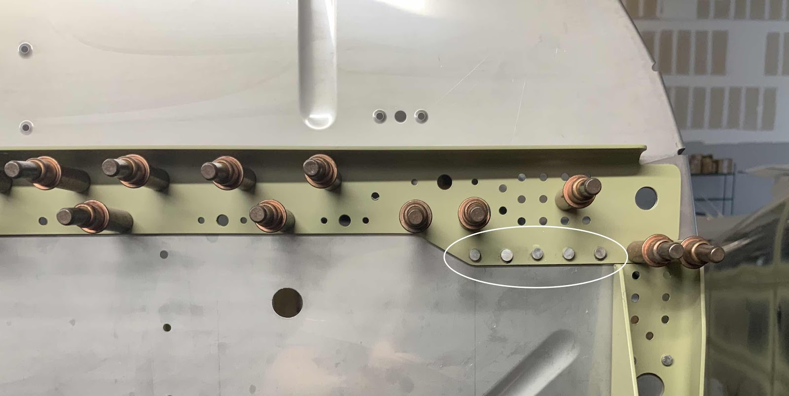
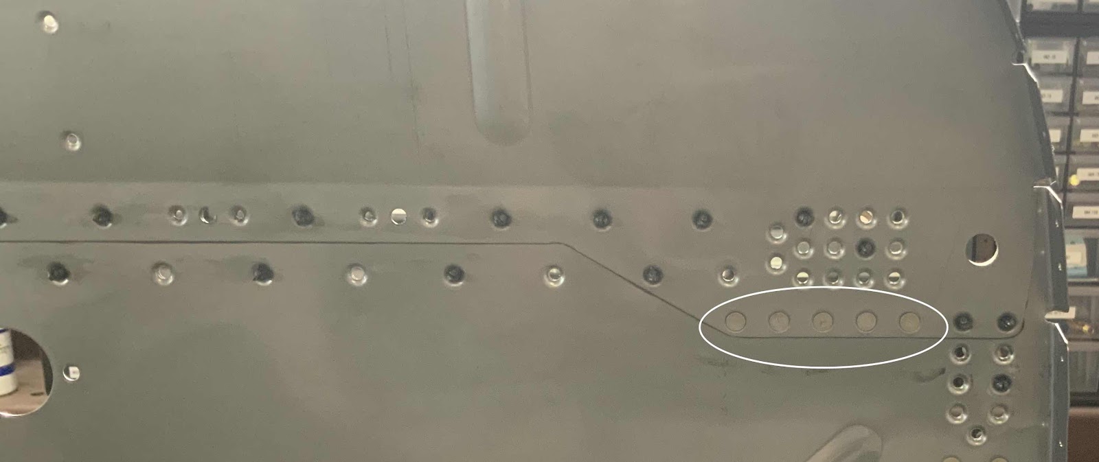
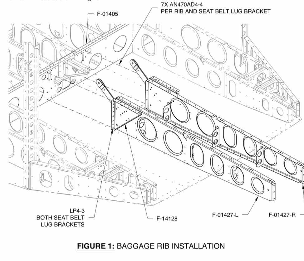
The first to go in are the F-01427-L & -R Baggage Ribs.  The were attached with a mixture of AN470AD4-4 and LP4-3 rivets.  The plans excerpt shows their installation location.
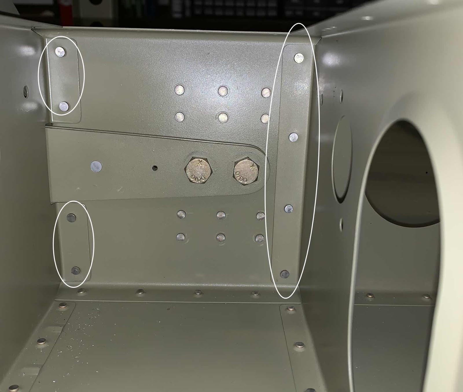
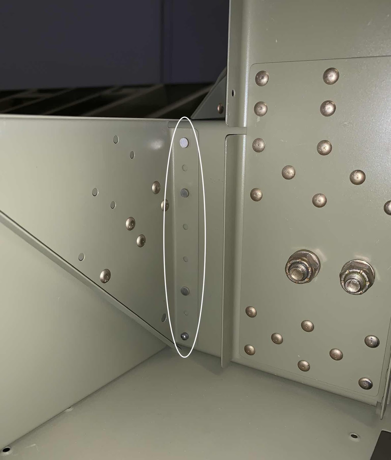
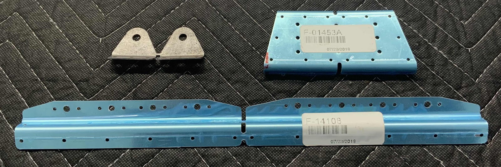
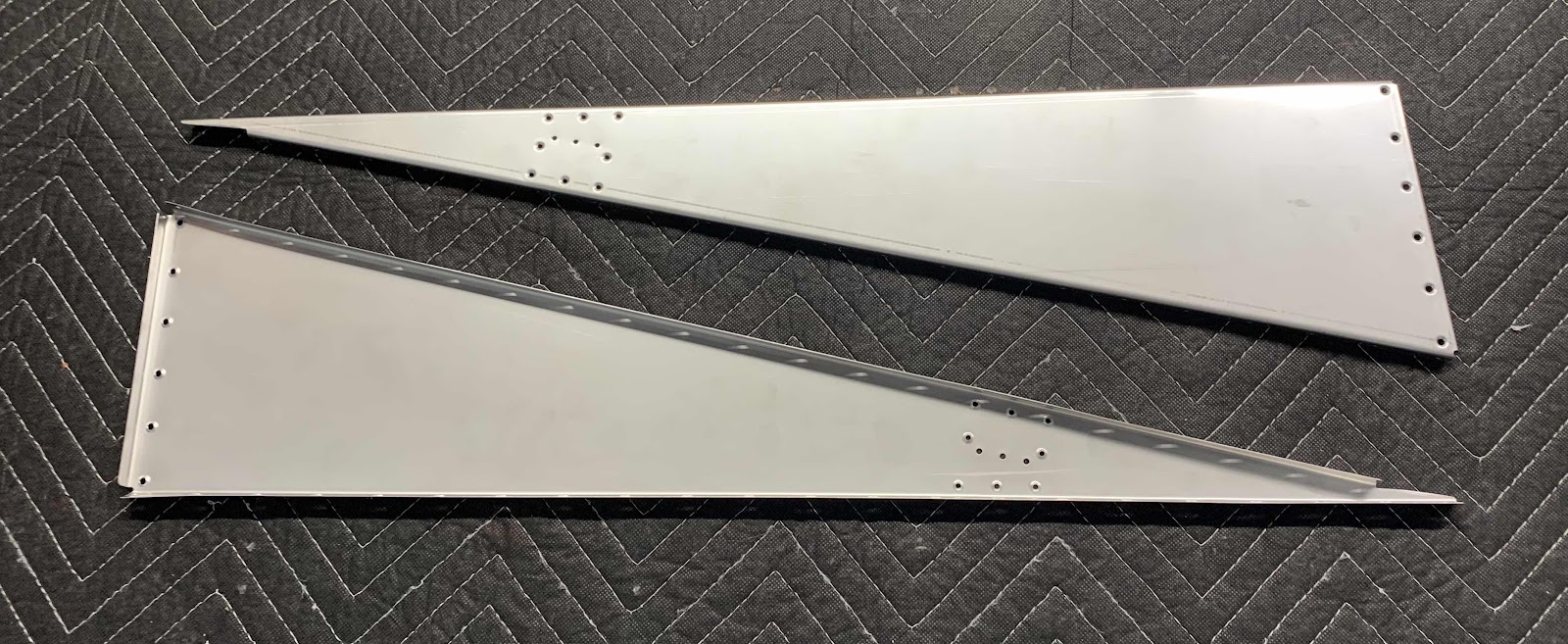
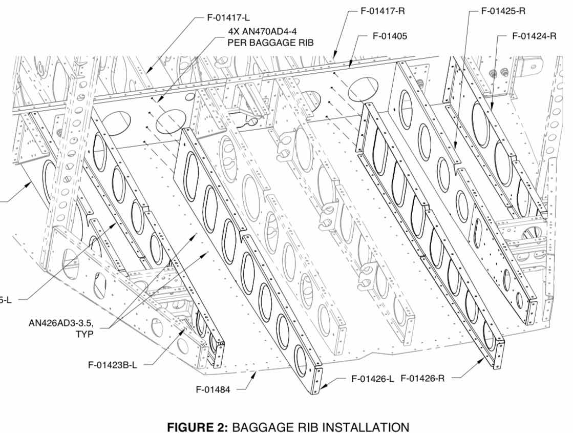
Next, the two F-01426-L & -R Baggage Ribs are attached to the Bulkhead with AN470AD4-4 solid rivets.


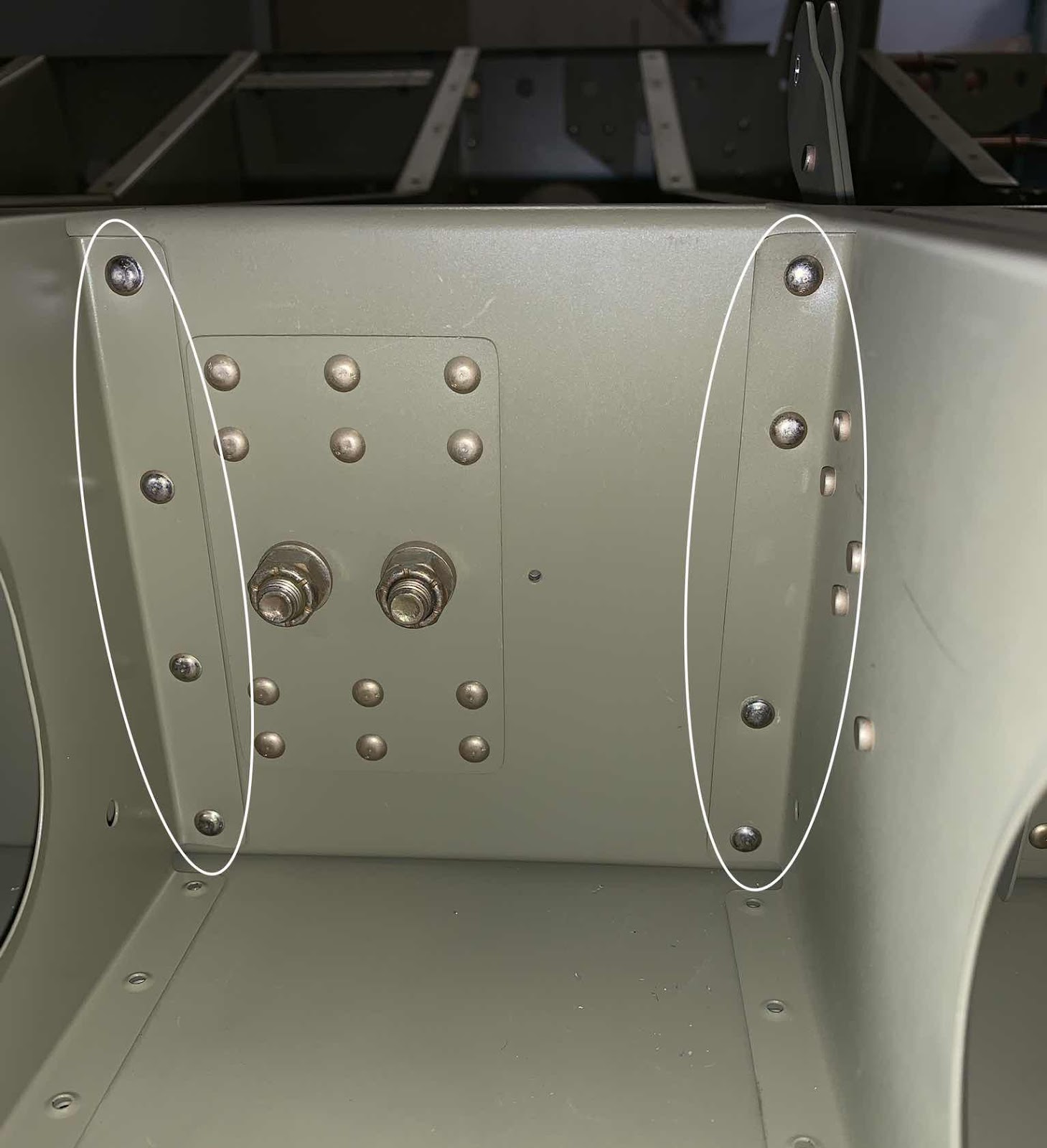
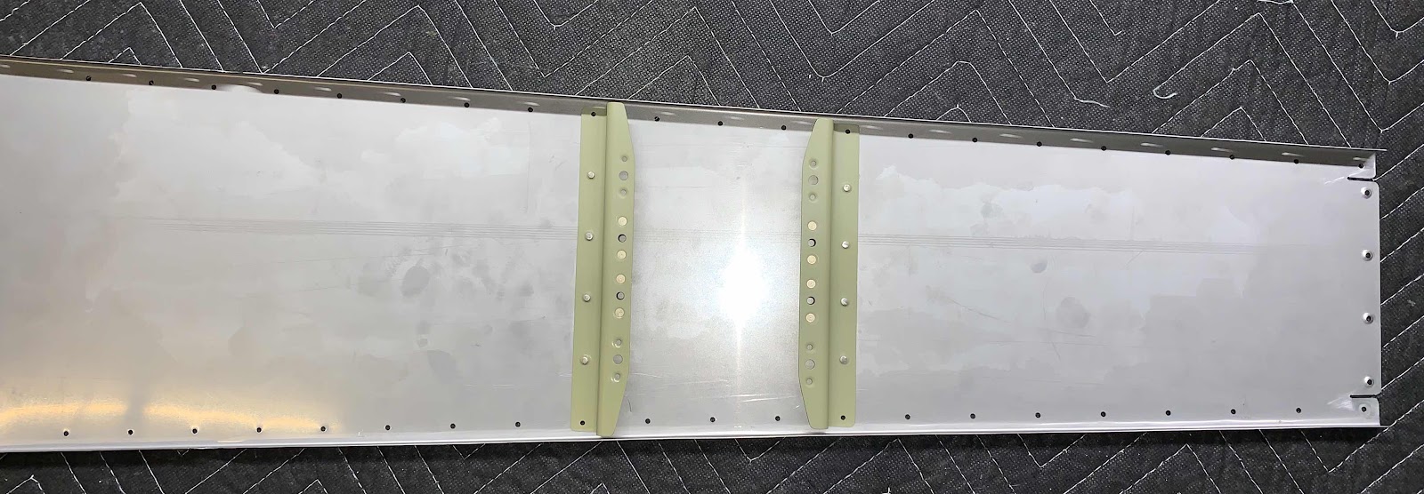
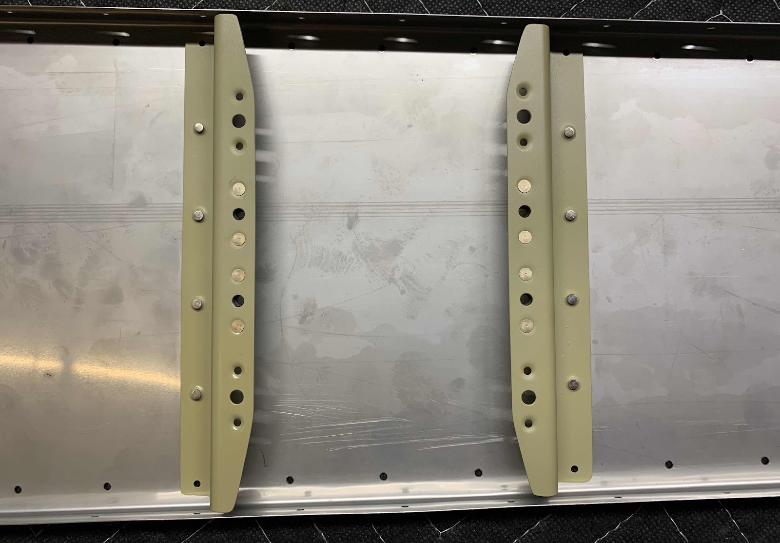
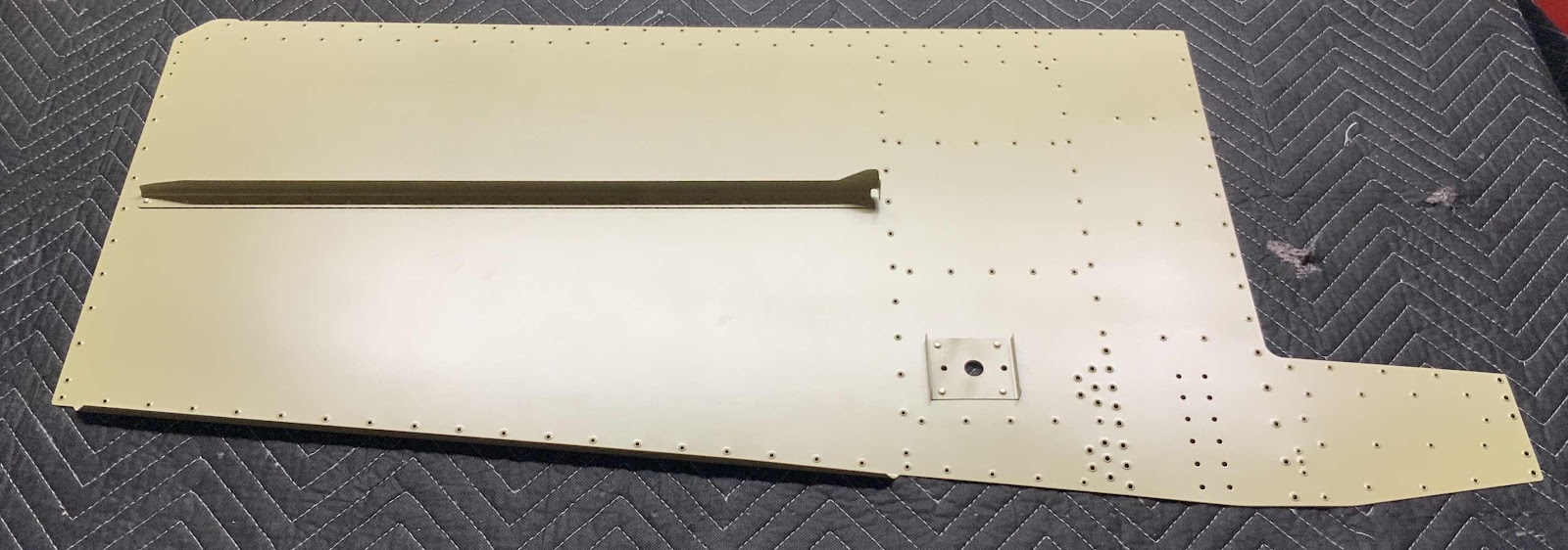
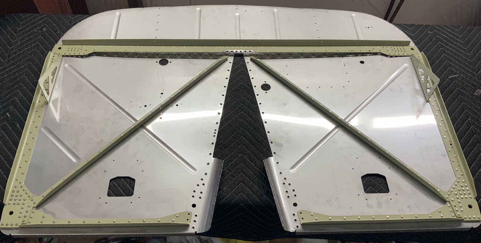
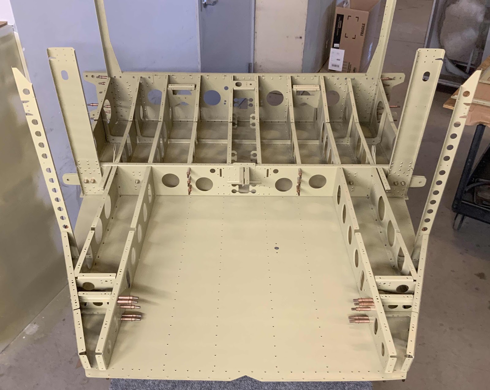
Lastly, here is the ALMSOT completed MID Lower Structure after the Baggage Ribs described above were installed.  The last step is to install the F-01430 Baggage Floor Stiffener.  In the picture below, you can see the Stiffener installed midway down the Baggage Ribs running horizontal across the baggage area.  The Baggage Floor Stiffener is attached to the F-01458-L & -R Side Frames and F-014234B-L & -R Outboard Baggage Ribs using two LP4-3 on each side.

Section Complete

Thursday, July 18, 2019

Fuselage, MID Lower Structure (Part 30)

In Part 26, we almost completed construction on the Step Attach Assembly.  The last step is to install the the remaining five rivets circled below.  The top and bottom are CR3213-4-2 cherry rivets and the other three are AN470AD4-5 solid rivets.  This is the right Step Attach Assembly.....

.....and the left Step Attach Assembly.

Now, the left and right Step Attach Assemblies are riveted to the F-01405 Bulkhead as indicated in plans excerpt below.

The rivets are installed in the F-01425-L & -R Baggage Ribs flanges, through the F-01405 Bulkhead, through the F-01424-L & -R and F-01425-L & -R Baggage Ribs flanges.  Here is the left forward side showing the shop head sides of the rivets (looking aft).....

.....and the manufactured head side (looking forward).....the right side was completed the same way.

This is the F-14128-R Seat Belt Lug Bracket (riveted to the F-01424-R Baggage Rib) riveted to the Bulkhead.  The bottom rivet is a LP4-3 blind rivet due to the limited space available to shot or buck the rivet.  The left side was completed the same way.

Wednesday, July 17, 2019

Fuselage, FWD Lower Structure (Part 5)

Tonight was a relatively short night, but still making forward progress.  The F-01453A-L & -R Muffler Shroud Doublers were installed in the Part 4.  The F-01465 Muffler Hanger Angles were also prepared and Akzo primed in Part 4.  During this sessions, the Hanger Angles were riveted to the F-01453-L & -R Muffler Shroud Sides (circled below) using AN470AD4-5 universal rivets.

Next, the two F-14108A Fuel Pump Brackets had four K1000-08 nutplates (two on each Bracket) riveted to them for later installation for the Electric Fuel Pump.  Then, the Brackets were riveted to the F-01454 Muffler Shroud Ramp as shown below.  The outer two holes on each Bracket DO NOT get riveted at this time.....only the four middle holes.  Each hole received AN426AD3-3.5.  Here is an overall view of the installed Brackets.....

.....and a close up.  I backriveted the eight rivets in this step.


Lastly, this is the “bottom” side of the Ramp showing the manufactured heads of the rivets installed in the Brackets above.

Monday, July 15, 2019

Fuselage, FWD Lower Structure (Part 4)

Another short session tonight, but progress is progress.  During the last session, I primed the Muffler Shroud Doublers.  Tonight, I riveted them to the Muffler Shroud Sides.  The first picture shows both sides of the Shrouds with the Doublers riveted into place using AN426AD3-3 rivets.  The second is a close up of the same.


Lastly, I primed the Muffler Hanger Angles.  Because the two Angles are steel and the Shroud Sides they attach to are Stainless Steel, I wanted to provide some corrosion protection.  These Angles will be attached in the three holes in the center of the Doublers shown in the two pictures above.

Sunday, July 14, 2019

Fuselage, FWD Lower Structure (Part 3)

Today’s session started by separating the F-01453A-L & -R Muffler Shroud Doublers, F-01465 Muffler Angles, and F-14108A & B Fuel Pump Brackets.....all shown below.  These parts have to be separated, deburred, and dimpled.  

After I separated the Muffler Shroud Doublers and Fuel Pump Brackets, I treated them with Alumiprep and Alodine.  Once they were completely dry, I sprayed them with Akzo primer.

These are the Stainless Steel F-01453-L & -R Muffler Shroud Sides.  The #30 holes (x6 each piece) along the forward webs were dimpled and the #40 holes (x8 each piece) in the webs were dimpled where the Muffler Shroud Doublers will be attached.  Finally, for these two pieces, I cleaned the rough edges on all the flanges.  Additionally, a small portion of the ends had to be trimmed from each Side and aft end of the upper flange had to be straightened as shown in the second picture below.


Here’s the F-01454 Muffler Shroud Ramp.  The #40 holes (x19) were dimpled in the web and lower-aft flange.   


Saturday, July 13, 2019

Fuselage, FWD Lower Structure (Part 2)

In Part 1, I prepared the Skin Stiffeners and Antenna Doublers.  Today, I will focus on the Forward Bottom Skins.  To prepare the Skins, each one had the following:
1.  Cleaned the edges
2.  Deburred the holes
3.  Enlarged the #40 Communications Antenna Hole to 9/16”
4.  Final-drilled #12 the Communications Antenna attach holes
5.  Broke the edges upward around the after perimeter
6.  Dimpled the #30 and #40 holes (except the ones covered in orange tape)

Lots of work accomplished on the these Skins.  This is the F-01483-L Forward Bottom Skin.....

......and the F-01483-R Forward Bottom Skin.

These are the Skins oriented OPPOSITE to how they will be installed on the plane.  I was just clowning around and took this picture because this orientation remains me Mississippi and Alabama!  It’s a little funny!  No?


After all the prep work was completed on the Skins, I treated them (along with the parts prepared in Part 1) with Alumiprep and Alodine.  Once they were dry, the were sprayed with Akzo primer.

Pictured below is the left Forward Skin with the Skin Stiffener and Antenna Doubler riveted into place.  Both parts received AN425AD3-3.5 rivets.  I backriveted all the rivets and produced almost perfect results.

Here is the right Forward Skin completed the same way as the left one above.

Friday, July 12, 2019

Fuselage, FWD Lower Structure (Part 1)


Relatively short session tonight.  Below are the F-01434-L & -R Skin Stiffeners and the two F-00020 Antenna Doublers.  Both the Stiffeners and Doublers had to be separated, their edges cleaned, holes deburred, and dimpled.  They are now ready to be treated with Alumiprep and Alodine and sprayed with Akzo primer.


Thursday, July 11, 2019

Wings, Aileron Actuation (Part 4)

Continuing on from yesterday’s work.....

Shown below are the four AN490HT8P Threaded Rod Ends.  Those four Rod Ends have to be inserted into the ends of the Bellcrank to Aileron Pushrods fabricated in Part 3.  However, the Rod Ends are a little fatter than the opening of the Pushrods.  

So, to fix this “problem”, I put two 7/16 nuts on the Rod Ends (far right in the picture above) to protect the threads of the Rod Ends.  Then inserted the nuts into a drill press as shown below, turned it on and used the vixen file to remove material from the Rod End.  Once enough material was removed, I used 220 grit sandpaper to smooth out any rough edges edges created by the file (careful not to make it to smooth and prevent primer from sticking to it in a later step).  Worked out very well.  (I stole the idea from Shawn).

Here are all four of the Threaded Rod Ends after being trimmed as described above (you can see the shiny ends).  Also shown are the two Pushrods that the Rod Ends will be inserted into.....

.....and the Rod Ends inserted into the Pushrods.  This is temporary as holes will have to be drilled and the parts riveted together.

The next step is to drill the two holes in each end for the install of the AN470AD4-11.  These rivets will hold the Pushrods and Rod Ends together.....more on that during the next work session.

Wednesday, July 10, 2019

Wings, Aileron Actuation (Part 3)

So, I’m currently in a position on Section 26 (MID Fuse Lower Structure) and Section 27 (Firewall) that I will need a rivet helper to finish up the sections.  So, I audibled back to Section 23 (Aileron Actuation) to finish some unfinished work.  Previously, I had to order four AN490-HT8P Threaded Rod Ends from Van’s, because I didn’t notice during inventory, that I had four of the wrong size (bigger).  So, I had to pretty much stop work on this section until the parts were delivered.  By the time they were delivered, I was already working on another section.....Section 23 had to wait.....until now!

Anywho, today’s session was spend working on the two Bellcrank to Aileron Pushrods.  In the picture below, all the white pieces made up one ST4130-035 x 1/2 rod measuring 48 inches.  From that rod, two CS-00013 Bellcrank to Pushrods had to be fabricated.  Each Pushrod had to be cut to a length of 21 3/8” long.  Initially, I cut the rod into two pieces 24” long (using the Milwaukee Rotary Tool with a cutting wheel).  From there, I trimmed those two pieces to roughly 21 1/2 inches (again, using the Rotary Tool).  Lastly, I used a hand file and the ATS air sander to get the final length correct.  Turned out pretty well.

I’ll continue the working on the Pushrods tomorrow.

Tuesday, July 2, 2019

Fuselage, Firewall (Part 8)

Continuing work on the Firewall.  During the last session, I back riveted the three Firewall Angles to the left Firewall Side.  During today’s session, I back riveted the three Firewall Angles to the right Firewall Side.  Here is the aft side of the Firewall showing the shop head side of the rivets.....

.....and the front side showing the manufactured head side of the rivets.  I had to drill out a few of the rivets today and redo them.  One of the rivets was “smashed” too much and two of the rivets (somehow) were off the edge of my backriveting plate.  This caused the rivet head to be deformed and actually cracked the head of the rivet.  So, I removed the three rivets (being extremely careful since I was working with the Firewall) and re-set them.  Much better results the second time around for those three.

The next step was to install the F-01401A Firewall Top to the Firewall Sides using the F-01401D Firewall Angle.  So, here is what it looks like un-clecoed and un-riveted.  Now, a couple of things were going on here: 

1.  Only 10 holes (5 on each end of the Angle get riveted)
2.  A 1/16” bead of fuel tank sealant (Proseal) needed to be put between the Firewall Top and Sides

These are the only five holes on the right side (aft side of the assembly) that will get rivets.....

.....and these are the five holes on the left side (aft side of the assembly) that will get rivets.

It might be a little hard to see in the picture below, but along the bottom edge of the Firewall Top (looking at the aft side of the part) is the small bead of Proseal I applied as described in the plans.  Now, the two Firewall Sides will be positioned on the Firewall Top and clecoed into place. 

Unless I was doing it wrong, I couldn’t find an acceptable way to backrivet these 10 rivets.  So, my buddy helped me shoot them....me on the gun and him on the bar.  Here are the manufactured heads of the five rivets on the right Firewall Side (looking at the forward side of the assembly).  This picture was also taken after I cleaned up the excess proseal that oozed out from the seam of the two parts.  (You can see the seam running left to right in the middle of the picture).

This is the opposite side of the picture above showing the shop head side of the rivets (looking at the aft side of the assembly)


Here are the manufactured heads of the five rivets on the left Firewall Side (looking at the forward side of the assembly).....

.....and the opposite side of the picture above showing the shop head side of the five rivets (looking at the aft side of the assembly).

The next step was to cleco the Left and Right Tunnel Side Assemblies to the Forward Firewall Assembly.  Here is what it looks like (looking at the aft side of the assembly).....

.....and this is the forward side of the assembly.  More to follow during the next session.


Section Complete