Tuesday, December 25, 2018

Fuselage Kit Ordered

!!!!!MERRY  CHRISTMAS!!!!!

ANOTHER big step!!!!!

On Friday, December 14, 2018, I completed the Fuselage Kit Order Form and emailed it to Van’s.  The Van’s website advises there is a 10 week lead time as shown below.  That will give me some time to finish the Wings prior to the next kit arriving.

As with all the other kits, I put down a 25% deposit.  The remaining balance will be charged prior to the kit being shipped in February.

*****Another motivational picture from Van’s Aircraft.....keep squishing them rivets*****
(Photo by Van’s Aircraft)

Friday, December 14, 2018

Wings, Fuel Tanks (Part 35)

Well, after a couple of months, Jeff and I were able to continue the work on the Right Fuel Tank.  During this session, we installed the seven T-1012 Tank Attach Zees and the T-00002 Tank Baffle.  As the instructions described, we applied a bead of Proseal on the Fuel Tank Skin from the Tank Baffle rivet holes forward.  By doing this, the Tank Baffle will  act as a “squeegee” and push the Proseal forward when installed.  Additionally, Proseal was applied to the aft flanges of the seven Tank Ribs.

Next, we installed clecos in EVERY hole that will be receiving a rivet.  Once the clecos were installed, we started riveting the Tank Baffle to Tank Ribs (starting from the center Tank Attach Zee, then working outward in both directions) and finished with the Tank Baffle to Tank Skin rivets (also starting in the center and working outward in both directions).  As with the Left Fuel Tank, the Right Fuel Tank will be receiving a combination of AN470AD4-4 and AN470AD4-5 solid rivets and AD-41H and AD-42H blind rivets in the locations indicated in the plans excerpt below.


Here is a aft section of the Right Fuel Tank after all the rivets have been installed.  In this view, you can see the seven Tank Attach Zees and their corresponding rivets.  For this installation, the closed end of the AD-41H and AD-42H blind rivets were “twirled” in Proseal prior to installation.  Additionally, you can see some of the black Proseal where the Tank Baffle and Tank Skin meet.

Here is a closer picture showing the solid AN470AD4-5 and 4-5 rivets installed on the Inboard Tank Attach Zee.  You can also see the area where the Tank Baffle and Tank Skin meet.

This is the Outboard Tank Attach Zee and corresponding area.

Kind of a cool shot down the length of the Tank Baffle showing all seven Tank Attach Zees. 

I’m not completely finished with the Tank Baffle and Tank Attach Zees just yet.  I will need to clean up several areas and apply additional Proseal to the areas where the rivets were installed and the seams around the parts.  I’m sure my personal “requirements” for Proseal application will be a bit overboard, but I DO NOT WANT THE TANK TO LEAK!!

Wednesday, December 12, 2018

Wings, Flaps (Part 6)


I continued with the dimpling from the previous session.  Tonight, I dimpled:

- - FL-00001-L Nose Skin (used pneumatic squeezer for the Spar attach holes and the DRDT-2 for the holes in the leading edge curved portion of the Skin with reduced diameter female die)

- - Eight Main Ribs (seven FL-1005- L’s and one FL-1005-R modified Main Rib) - (used hand squeezer)
- - Three FL-1004-L Nose Ribs (used hand squeezer)
- - One FL-1005-R Nose Rib (used hand squeezer)
- - Two FL-1004-L Nose Ribs that make up the Left Hinge Pair Rib Subassembly (used hand squeezer)
- - Two FL-1004-R Nose Ribs that make up the Right Hinge Pair Rib Subassembly (used hand squeezer)

Now, there were four holes on each of the eight Main Ribs that my hand squeezer would not get to without distorting the opposite flange.  The four holes are circled in the picture below.

I decided to use my 3/32 (#40) Close Quarters Dimple Die I purchased from Cleaveland Aircraft Tool.  This worked out great and produced very good dimples.  Below, are the two dies and the “nail” that is used for the hand riveter to pull.

This is the set up.....


.....and these are the results.


Now, the only thing left to do before Alumiprep, Alodine, and primer is countersink the holes in the V-Channel.  I will do that during the next session.

Tuesday, December 11, 2018

Wings, Flaps (Part 5)

I continued prepping parts for the Left Flap and made some great progress.  

- - cleaned the edges of the FL-00002A Top Skin
- - cleaned and deburred the Right Hinge Pair Rib Subassembly (FL-1007-R Hinge Bracket and FL-1004-R Nose Rib)
- - cleaned and deburred the FL-1004-L Nose Rib for the Left Hinge Pair Rib Subassembly 

 That completes the cleaning and deburring for ALL of the parts and pieces that make up the Left Flap.  

Now, moving on to dimpling.....  

- - dimpled the FL-00002A Top Skin (using the DRDT-2)
- - dimpled the FL-00002B Bottom Skin (using the DRDT-2)
- - dimpled the FL-00003-L Spar (using the pneumatic squeezer with a reduced diameter female die)

Monday, December 10, 2018

Wings, Flaps (Part 4)

I had a relatively short session tonight.  I was able to debur and clean three more FL-1005-L Main Ribs and FL-00002B Bottom Skin.

Sunday, December 9, 2018

Wings, Flaps (Part 3)

I spent today’s session deburring and cleaning the edges of several pieces of the Left Flap.  These pieces included the FL-00003-L Spar, FL-00001-L Nose Skin, two FL-1004-L Nose Ribs, three FL-1005-L Main Ribs, and the Inboard and Outboard Rod End Rib Subassemblies.

I will debur and complete the the edge work for the remaining parts of the Left Flap during the next session.

_______________________________________________________________________________________________


Work Completed on Saturday, December 8, 2018

Previously, the #40 hole locations were measured and drilled in the joggled portion of the FL-1007-L Hinge Brackets.  Today, the #40 hole locations for the matching FL-1007-R Hinge Brackets were match-drilled using the left as a guide.

The picture below shows the Inboard Subassembly.  You can see the four holes in the Left Bracket (in between the clamps) that will be used as guides to match-drill the Right Bracket.  I installed the the hardware in the hole where the Subassembly will be attached to W-1025A Flap Hinge Bracket (already installed on the Left Wing).  This helped to hold the Subassembly together and tight (along with the clamps) for the match-drillling.

Opposite side of the same Inboard Bracket above.

The Outboard Subassembly prepared for match-drilling.

Wednesday, December 5, 2018

Wings, Fuel Tanks (Part 34)

After completing all of the Left Fuel Tank fitting during the last session, today I installed the Fuel Tank for the final time.  Each Fuel Tank is held on to the Wing/Spar by 18 AN3-4A bolts, 3 AN3-5A bolts, and ‘77 AN509-8R8 screws as shown in the plans excerpt below.


Here is the actual bolts that will be used for the installation.  The three AN3-5A bolts are on the far right....the rest are the AN3-4A bolts.  I installed these bolts through the Spar FIRST, and then installed the screws.  Might not make that much of a difference, but I think the bolts would “pull” the tank flush against the Wing Spar.  For corrosion resistance purposes, I previously primed the Wing Spar during Section 13.  As a result, there is already a “layer” of primer between the Wing Spar and the bolt washer.

Pictured below are the three AN-3-5A bolts attaching the Fuel Tank on the inboard side of the Wing.

Here are a few examples of the AN3-4A bolt locations taken from the Access Panel locations on bottom of the Left Wing.  At the top of each of the pictures, you can also see the installed AN509-8R8 screws and nutplates that attach the Fuel Tank to the Main Wing Spar.  


Since the screws being installed are steel and the skin is aluminum.....corrosion because of the dissimilar metals. To add some level of corrosion protection, I will use a paint brush to brush Akzo Primer on the screw holes and install the screws “wet”.


Here is the primer brushed on.....


.....and a screw being installed.  After the screw was properly set, I used a rag with MEK to remove the excess primer (screw on the left).  This will all get painted over later when the whole airplane is painted, but putting some primer between he screw and skin made me feel better.

After all of the screws had been installed, the Left Wing was put back in the wing cradle until the next step.


Tuesday, December 4, 2018

Wings, Fuel Tanks (Part 33)

Today’s session focused on fitting the Fuel Tank to the Left Wing and making any necessary modifications (filing, sanding, etc) prior to final installation.  The “top skin” of the Fuel Tank fit perfectly to the Spar and Outboard Leading Edge and required no modifications for the desired fit.

However, the “bottom skin” required some sanding for the fit I was looking achieve.  I had to install and remove, install and remove the Fuel Tank several times until I was happy with the fit.  The effort resulted in very good results.  The screws installed in the pictures below are temporary and are used solely to check the fit of the Fuel Tank.  The plans state:

“The edges of the T-00001 Fuel Tank Skin must have a zero to 1/64 [0.4 mm] gap between the adjacent wing skin edges.  A larger gap may be desirable if the aircraft is to be painted, while a zero gap may be desirable if the aircraft is to be left in natural aluminum”

I definitely plan on painting the airplane, so......

The picture below shows where the inboard section of the Fuel Tank joins the Left Wing.  This area had to be sanded to achieve the fit described above.

This is the middle, aft section of the Fuel Tank where it joins to the Main Spar.  This area also had to be modified.....

Lastly, here is the inboard section of the Fuel Tank....just forward of the wing walk area (on the top of the wing).  Again, this section also had to be modified for the desired fit.


Monday, December 3, 2018

Wings, Fuel Tanks (Part 32)


After completing the rivet installation in the last session, today I started the initial fit of the Left Fuel Tank to the Left Wing.  I didn’t make any huge strides today, but did get the visual of how the Fuel Tank attaches and what need to be done prior to installing the tank.  Specifically, some areas that will need to be modified (sanded) prior to final installation. 

The three pictures below show the Fuel Tank temporarily attached to the Left Wing.  Like I said, this is temporary and provides me with the visual I need for the final installation.

Outboard section of the Fuel Tank that joins the Outboard Leading Edge.....

.....aft section of the Fuel Tank that joins the Left Wing Main Spar....

.....and finally just an overview of the Fuel Tank attached to the Left Wing.


Wings, Bottom Wing Skins (Part 16)

In Part 15, I completed riveting the Bottom Inboard and Outboard Wings Skins on the Right Wing.  Now, I’m moving on to the Left Wing.  As with the previous post, this will also be an all encompassing post for the 12 works sessions it took to complete riveting the Bottom Skins on the Left Wing.


Friday, November 16th:  66 Rivets
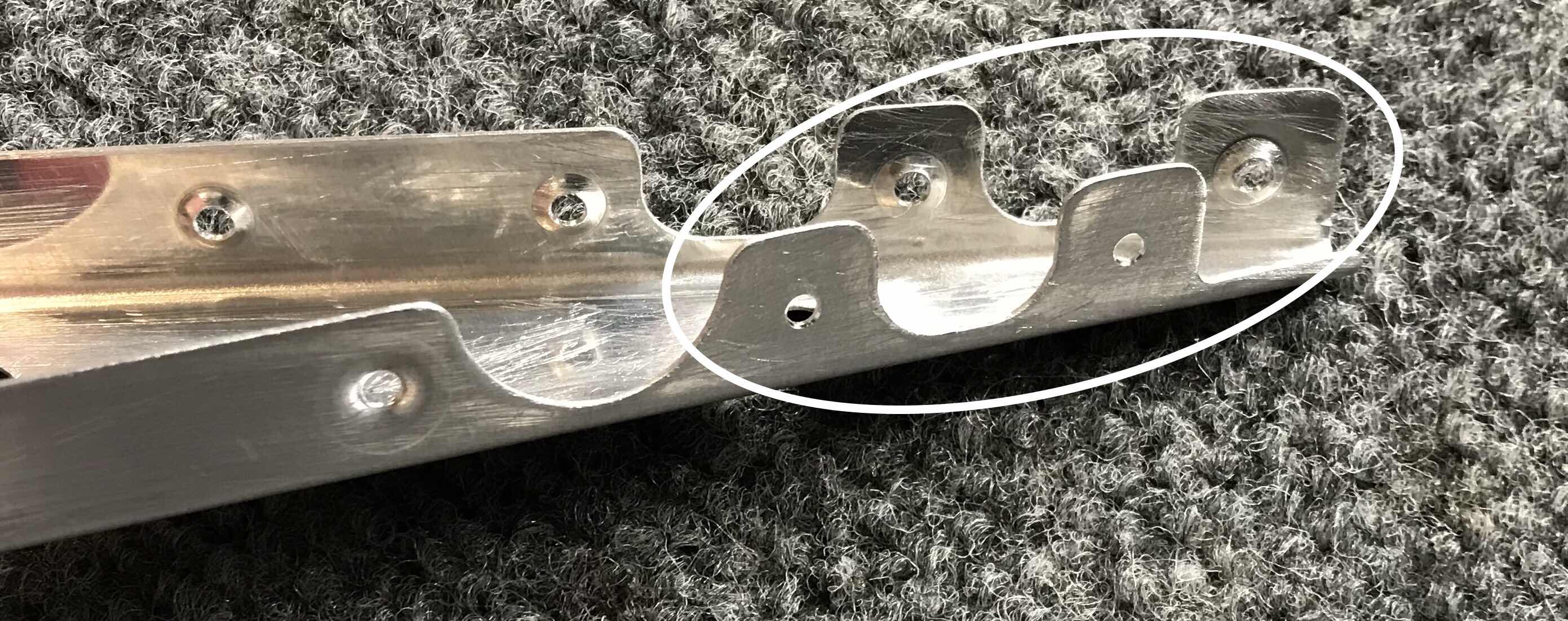
When I was counersinking the Fuel Tank Attach screw holes in Section 13, I accidentally let one of the holes get bigger than it was supposed to be.  So, after lots of colorful adjectives, I decided to take a deep breath and fix it LATER.  Well, LATER is now.  The countersunk hole essentially provides a “cavity”, if you will, for the corresponding dimpled Tank Skin to sit in when it is screwed into place.  Because the hole is presently too big, when the screw is installed it would “pull” the Tank Skin into the cavity and deform the Tank Skin.....can’t be having that!  Since I removed to much material (aluminum), I have to ADD some material.  After consulting several A&P’s and previous RV builders, I decided to use Hysol as a filler.  Hysol is used as a structural glue on many different certified aircraft models.  So, I figured it was the best fix for my “problem”.

First, I drilled out the two rivets that held on the nutplate (as shown below) and put a piece of metal tape on the underside of the Spar Flange under the hole in question.  Once the Hysol was properly mixed and cured, I filled the hole and let it dry.  After the Hysol was dry, I sanded the area with 220 grit sandpaper to smooth out the Hysol to the Spar Flange.  Lastly, I sprayed on some new primer to make it look “pretty”.  NOTE:  the primer is NOT on the Flange in the picture below.....its not pretty!

Next, I used clecos to hold the nutplate in position on the OUTSIDE of the Main Spar Flange.  I then used the nutplate as a guide to drive the screw hole through the Hysol.  Lastly, I used a hand deburring tool to make the appropriate countersink in the Hysol for the dimpled Tank Skin.  To hold the nutplate in place to re-install the rivets, I partially installed one of the Tank Attach screws as shown below.  Once the nutplate was back into place, the “repair” was acceptable.....build on!!!

Here are the first rivets that were installed on the Inboard Bottom Wing Skin.


Saturday, November 17th:  8 Rivets

Wednesday, November 21st:  89 Rivets


Friday, November 23rd:  74 Rivets


Saturday, November 24th:  45 Rivets
I’m not really sure why I did this, but I decided it would be a good idea to rivet the angle bracket for the Pitot Tube base plate on the Wing Rib.....shouldn’t have done that.  The lip of the base plate goes UNDER the Main Spar Flange and OVER the angle bracket.  Let’s just say....IT DON’T WORK when trying the rivet the on the Wing Skin.

This is the opposite angle of the Pitot Tube Mount from the picture above.

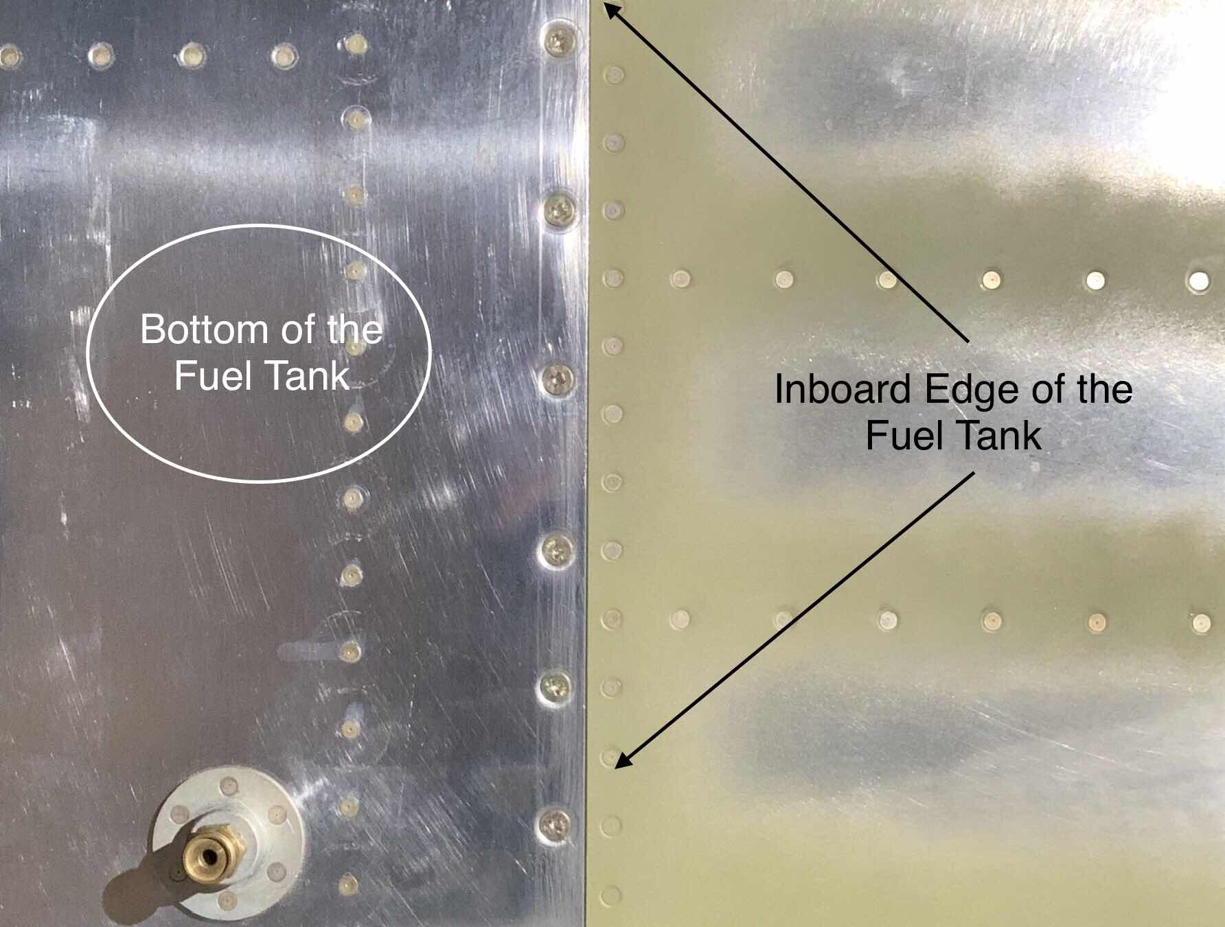
The inboard edge.....

.....and the outboard edge.  You can see the two manufactured heads of the rivets used to attach the Angle Bracket to the Wing Rib.....

.....and the associated shop heads.  I eventually had to drill out these rivets and remove the Angle Bracket.  This allowed the Pitot Tube Mast to be easily installed through the Access Panel.  The Angle Bracket will be installed within the next few work sessions after the Skin in riveted on the Wing.


Sunday, November 25th:  32 Rivets

Wednesday, November 28th:  33 Rivets

Friday, November 30th:  91 Rivets


Saturday, December 1st:  100 Rivets

Sunday, December 2nd:  146 Rivets
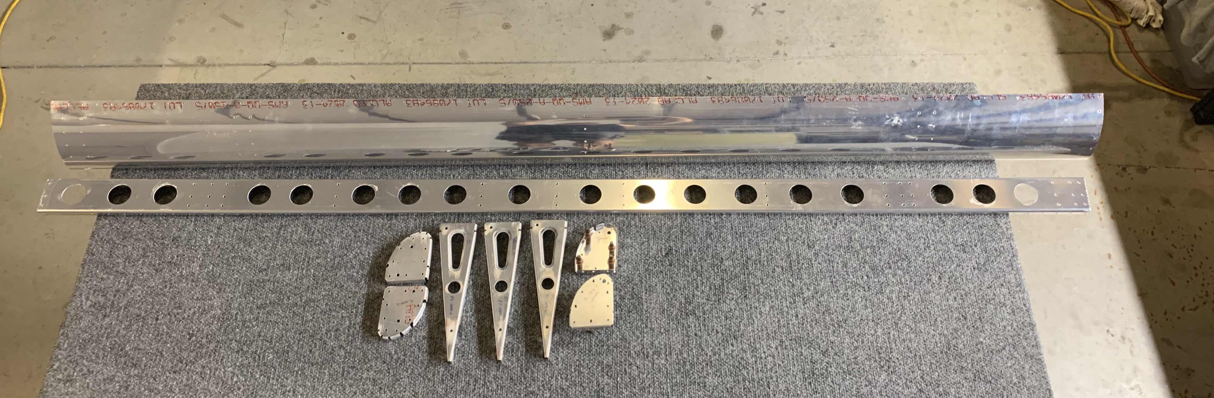
Now that all the rivets have been set for the Bottom Wing Skins, it’s time to install the Pitot Tube Mast.  It’s a whole lot easier now since I removed the Angle Bracket....which will be riveted to the Pitot Tube Mast base plate and Bottom Skin where the orange tape is located.  Since this is a “custom” install, I had to insert several different AN426AD3 rivets to get the proper length rivet because of the thickness of the Pitot Mast base plate.

The Skins are now riveted to the Pitot Tube Mast base plate.

Another view of the Pitot Tube Mast.


Monday, December 3rd:  3 Rivets
Lastly, the Angle Bracket was re-installed to the Wing Rib and Pitot Tube Mount base plate as shown in the picture below.  I decided to make a modification to the Angle Bracket.  Originally, the Angle Bracket that attaches to the base plate touched the welding bead around the base plate and Pitot Tube Mast.  I didn’t like this, so I trimmed the Angle Bracket away from the welding bead.  I also considered doing the same thing where the Angle Bracket gets riveted to the Wing Rib.  You can see a slight “gap” between the Angle Bracket and Wing Rib lightening hole in the picture below.  In order to trim this part of the Angle Bracket flush with the web of the Wing Rib (and lightening hole), it would be to close to the rivet for the proper edge distance.  I decided to leave it the way it was.  Like I said in a previous post, the Dynon Pitot Tube Mast is not designed for the RV-14, so I had to make a few modifications.....such as in Parts 11 and 12.

The completed installation of the Pitot Tube Mast.


Section Complete