Wednesday, September 30, 2020

Wings, Aileron Actuation (Part 5)

I previously started work on this section back in March of 2019.  Again, since we are waiting on the Finishing Kit, I’m completing small unfinished jobs.....this is another one of them.

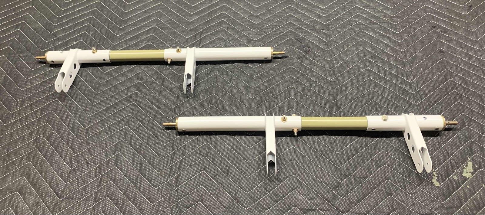
Below are the two CS-00009PC Aileron Torque Tubes and two VA-162 Pushrod Ends.  The Pushrod Ends get inserted into the “long” end of each of the Torque Tubes.  The two pieces were then match-drilled #30 to the prepunched holes in the Torque Tube.  The pieces were then disassembled, deburred and primed.  I used a paint brush to paint the inside portion of the Torque Tube that will accept the Pushrod Ends and the “flange” of the Pushrod Ends.

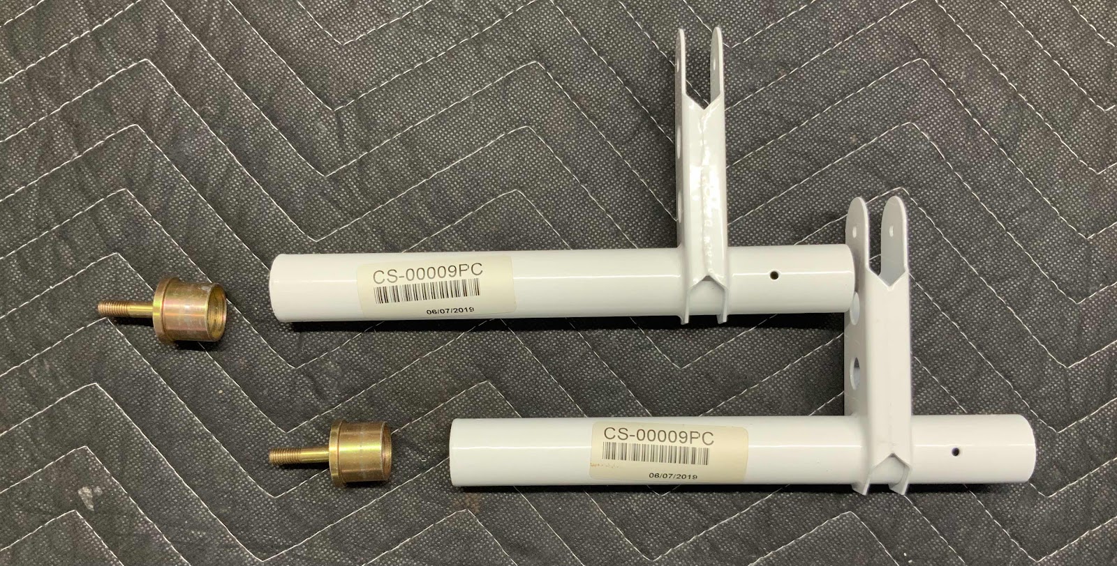
The Pushrod End were then inserted back into the Torque Tube (still wet with primer) and riveted together with four MSP-42 rivets (two on each assembly).  This picture shows the rivets installed.  This assembly is now called the CS-00009 Torque Tube Subassembly.

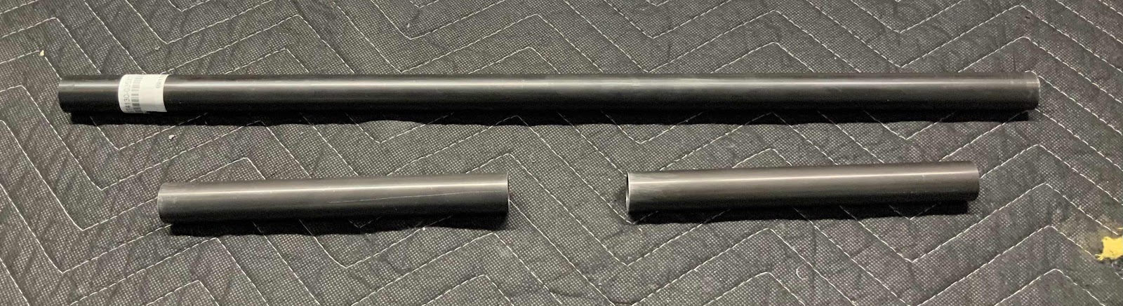
The next step was to fabricate two CS-00009B Torque Tube Collars with stock ST4130-035x7/8x22.  Each Collar is cut to 7 5/16 [185.7 mm].  The picture below shows the stock material and the two Collars cut to length.  I used a hacksaw for the initial cut and sanded to the exact length with 220 grits sandpaper.

The Collars get inserted 1 1/2” [38.1 mm] into the CS-00009 Torque Tube Subassemblies.  So, I measured 1 1/2” from one end of each Collar and marked them with a sharpie.  The Collar was then inserted into the Torque Tube Assembly up to the 1 1/2” mark.  The Collar was then match-drilled with the four pre-punched holes in the Torque Tube.  Now the pieces need to be primed.  I used a large syringe to squirt primer “inside” the Torque Tube Subassembly and rotated it around to cover the entire inside with primer.  I then used orange tape to mark off the 1 1/2” on the Collar and used a spray gun to paint the remaining portion of the Collar.  Lastly, I use a paint brush to coat the 1 1/2” portion of the Collar and inserted the two pieces together.  They were secured together using two AN3-13A bolts, NAS1149F0332P washers and MS21042-3 nuts.  This picture shows all of that completed.  I will eventually torque the four bolts.

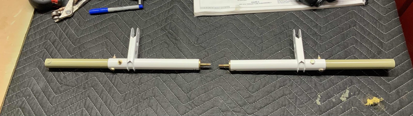
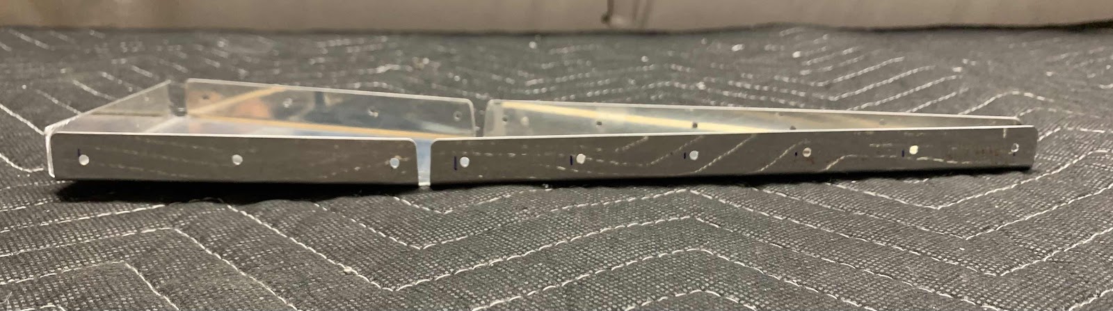
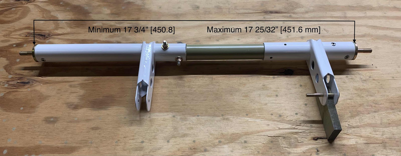
On the right hand side of the picture below is the WD-1014 Torque Tube Subassembly.  It was previously completed in the same manner as described above for the CS-00009 Torque Tube Subassembly (specifically, the attachment the VA-162 Pushrod End).  Now, with the second Subassembly completed, it also needs to be attached to the Collar.  The plans call for the minimum and maximum distances shown below.....(I chose the middle.....451.2 mm).  Once the distance is set, the four prepunched holes in the Torque Tube Assembly are match-drilled to the Collar and clecoed.

Lastly, for now anyway, a temporary bolt was installed in one of the match-drilled holes with the WD-1014 Torque Tube Subassembly to hold the assembly together and keep the appropriate parts together.  The next step is to install the assembly into the Wing Root area.....which I will do in a later session.


Wings, Wing Tip (Part 9)

In Part 6, we completed this work for the left Wing Tip Fairing.  Tonight, we will complete the work on the right Wing Tip Fairing.  We also used the same measurements from Part 6 to make our rivet patterns on this Fairing.  I marked the rivet pattern much better on this Fairing than the last, so hopefully it’s easier to understand (it was for me).  Here is the rivet pattern for the top of the Fairing.....

.....and the rivet pattern for the bottom of the Fairing.

The top of the Fairing after match-drilling.....

.....and the bottom of the Fairing after match-drilling.

After completing the match-drilling, we removed the Rib and inspected the rivet holes.....looks like our measurements also worked great for this Rib.

Lastly, the 19 holes (10 on the top and nine on the bottom) were countersunk for either an AN425AD3 or MK-319 rivet (more on the rivets during another session).  Here is the completed countersinking on the top of the Fairing......

.....and the completed countersinking on the bottom of the Fairing.

After completing the required countersinking, I treated the right and the left Rib with Alumiprep, Alodine and Akzo primer.  They are hanging up to dry and will be ready to install during the next work session.


Tuesday, September 29, 2020

Wings, Wing Tip (Part 8)

Today was a very LONG and productive day!  In previous work session(s), we completed the left Wing Tip Fairing up to the point of trimming the trailing edge of the Faring to match the trailing edge of the Aileron AND installing the “new” landing light insert (more on that in a later work session) for the AeroLED lights.  I started today by trimming the Fairing “flange” to the required 1/2” [12.7 mm]....I didn’t take any pictures after completing the trimming, but man look how fast I’m going.....


After the trimming was completed, the next step was to match-drill #40 the Wing Tip to the Wing (using the pre-punched holes).  The first picture below shows the completion of the match-drilling on the Top of the Wing.....

.....and on the bottom of the Wing.

Next, the Wing Tip was removed, the holes used as #40 drill guides were final-drilled #27, deburred and dimpled for a #6 screw.  Here’s the forward part of the Wing showing the dimples on the Top and Bottom Skins.....

.....and the aft portion showing the dimples on the Top and Bottom Skins.


That essentially completes the preparation on the Wing itself.  Now, we’ll shift work back to the Wing Tip.  Just like with the left Tip, the right Tip also gets 42 K1000-06 nutplates installed on the Wing Tip flange.  To do this, use the center screw hole on the Flange and a K1000-06 nutplate to locate the nutplate attach holes.  The nutplate attach holes get match-drilled to #40 and countersunk to accept the head of an AN3426AD3 rivet.  The center screw hole also gets countersunk to accept the dimpled Skin from the previous step.  The following pictures show the completed process.....


All of the 42 nutplates have been installed using AN426AD3-4 rivets and the Wing Tip was temporarily screwed into place on the Wing.  Here is the right Wing tip with all the nutplates installed.


There is still a little bit of trimming required to complete the final fit.  I found it much easier to see what trimming was required with Tip actually installed on the Wing. This shows the clearance between the Tip and the Aileron in the down position.....

.....and in the neutral position.

I’ll complete the trimming during the next session.

Monday, September 28, 2020

Wings, Wing Tip (Part 7)

Fairly short session tonight.  I machined countersunk the 10 holes on the top and the nine holes on the bottom of the Wing Tip Fairing.

Here are the nine countersunk holes in the bottom of the Fairing.  The forward six holes were countersunk to accept AN426AD3-3.5 rivets and the aft three holes were countersunk to accept the MK-319 rivets.

Here are the 10 holes on the top of the Fairing.  Just like on the opposite side of the Fairing, the forward seven holes were countersunk for AN426AD3-3.5 rivets and the aft three holes were countersunk for MK-319 rivets.  I did, however, make an errant hole in the Fairing.....can you see it?


Just forward of the forward most hole is the “oops hole”.   I didn’t highlight this error in any previous sections because I had holes and blue lines drawn all over the Fairing.  It would have been confusing and hard to explain....after all, I confused myself and drilled the hole.  So, the “oops hole” location is actually at the END of the the Wing Tip Rib.  I was supposed to measure aft 5/16 [7.9 mm] from the end of the Rib and make the hole.  The correct hole location is the hole immediately to the left of the “oops hole”.  Not that big of a deal since the Wing Tip is fiberglass.  I will just fill it later and you’ll never know it was there.

At this point, I’ll switch over to working on the right Wing Tip Fairing and prepare it to the same point as this one.  That way I can alumiprep, alodine and prime the Ribs together and complete the final assembly.

Saturday, September 26, 2020

Wings, Wing Tip (Part 6)

After installing all the nutplates on the Wing Tip Fairing.....it now needs a rib!  The W-1016-L Wing Tip Rib was inserted into the Wing Tip Fairing.  The plans state to “position the wing tip rib to fit snugly into the wing tip without distorting the wing tip or rib web”.  With the Rib installed in this manner, the forward and aft ends of the Rib was marked on the Fairing.  Here you can see those marks.....far left and right of the picture.  Next, measure 5/16” from each of those marks (toward the center of the Rib) and 5/16” from the inboard edge.  Those two “points” become the starting points for all the measurements.

Now, here is where the plans lost us.  Van’s provided measurements for a rivet pattern to attach the Wing Tip Rib.  For some reason, we weren’t able to make those measurements work and keep the holes on (over) the Wing Tip Rib flanges.  I’m sure they are probably right and if someone showed us....we would say “OH”.  But, we couldn’t make it work. So, there are four flanges on each Rib (two on the top and two on the bottom).  Instead of only marking the “points” on the outer edges of the flanges, we made a 5/16 “point” on EACH end of EACH flange.  To get our rivet pattern:

1.  We measured the distance between the 5/16” marks on each flange
2.  Consulted the plans to see how many rivets they wanted on each flange
3.  Divided the distances by the number of rivets.

Here is what we came up with:

  Top two flanges:
Short flange rivet spacing is 35.6 for four rivets
Long flange rivet spacing is 36.07 for six rivets

Bottom two flanges:
Short flange rivet spacing is 47.45 for three rivets
Long flange rivet spacing is 38.61 for six rivets

This picture shows the bottom of the Wing Tip Fairing with the marks based on our measurements.....

.....and this is the top of the Wing Tip Fairing with the marks based on our measurements.

After verify all the marks were appropriate and accurate, we match-drilled the holes in the Fairing and Rib.  This is the top of the Fairing with the 10 holes match-drilled.....

.....and the bottom of the Fairing with the nine holes match-drilled.

After all the holes were match-drilled, we removed the Rib.  Looks like our measurements worked out great.  Here are the 10 holes drilled on the top flange.....

.....and the nine holes on the bottom flange.

Friday, September 25, 2020

Wings, Wing Tip (Part 5)

Continuing on with work from Part 4.....

Tonight, we completed the locating and drilling #40 all of the nutplate attach holes in the upper and lower flanges of the Wing Tip Fairing.  Here are a couple of pictures showing completion.


After all of that, the 42 K1000-06 nutplates were installed using 84 AN426AD3-4 rivets and my hand squeezer.  Here is the completed front portion of the Fairing.....

.....the middle portion.....

.....and the aft portion.


Thursday, September 24, 2020

Wings, Wing Tip (Part 4)

After completing the match-drilling described in Part 3, the Wing Tip Fairing was removed from the Wing.  After some clean up, the #40 holes in the Leading Edge Skin, Top Outboard Wing Skin and Bottom Outboard Wing Skin were deburred, final-drilled #27 and dimpled for #6 screws.  Here is an overall look at the completed work.


Now, moving on to preparing the Wing Tip Fairing for the 42 K1000-06 nutplates.  The #40 match-drilled holes from Part 3 will be used to locate the nutplate attach holes for the nutplates.  The plans say to use temporary screws to hold the nutplates in place.  However, #6 screws won’t fit through a #40 hole.  So, I decided to go ahead and final-drill these holes to #27 to allow a #6 screw to fit (the plans have you do that anyway in a few steps, so I just did it “early” I guess).

To start, I used a flexible ruler to draw a line along the length of the Fairing to connect all the center screw holes.  Then I inserted a #6 screw (backwards through the hole) and attached the nutplate (on the incorrect side).  This allow you to line up the nutplate attach holes with the previously drawn line to get the nutplates as straight as possible.  The picture below shows an example of this process.

I ran out of time tonight to compete the process for the entire Fairing, but will pick up here during the next session.


Sunday, September 20, 2020

Wings, Wing Tip (Part 3)

Tonight’s session started with temporarily installing the left Aileron on the left Wing using AN3 bolts.  This is necessary to ensue you have the proper clearance between the Aileron and the Wing Tip.  This picture shows the Aileron attached to the Outboard Hinge Bracket.....

.....and the Inbound Hinge Bracket.

One area the plans are specific about are:
“Verify the gap spacing between the forward edge of the A-1016 Aileron Hinge Bracket and the Wing Tip when the Aileron is rotated to full trailing edge up deflection”
So, here is the Aileron taped in the fully up position.  This picture shows the angle looking from inboard to outboard.....

.....and outboard to inboard.

Next, the Wing Tip gets inserted into the Wing.  In order to hold the Wing Tip into position, the plans say to use a ratchet strap as shown in the plans excerpt below.  This is designed to make sure the Wing Tip if fully seated against the inside of the Wing’s leading edge.  I found this to be very difficult (maybe I wasn’t doing it right).  I found it much easier for one person to hold the assembly in position and a second person to match-drill the required holes.  I assume the ratchet strap idea is in case you are working by yourself.  Probably a good idea, I just couldn’t get it to work.


So, once it was held in position (by a second person in my case), all the #40 holes in the Leading Edge Skin, Top Outboard Wing Skin and Bottom Outboard Wing Skin were match-drilled with the Wing Tip.  The next two pictures shows the completed process for the top and bottom of the Wing Tip.


This is the initial fit for the “gap” between the Wing Tip and the Aileron.  At little “wavy”, but can easily be fixed with some sanding.  I won’t do any “sanding to fit” at this point, because I want to install the 42 nutplates onto the Wing Tip and screw it into its final position.  Once that is done, I will make any necessary sanding adjustments to the Wing Tip.