Saturday, October 31, 2020

Finishing, Miscellanea (Part 4)

I had to prepare and prime some parts for Part 1 of the Canopy and Window, so I deceived to prepare a few of the cabin area cover plates.  The parts didn’t take much time to prepare and were finished quickly.

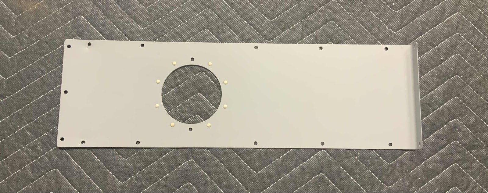
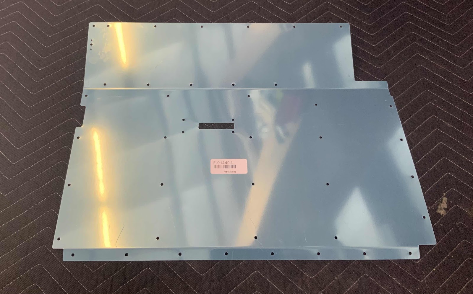
Here is the F-01440-L Seat Ramp.....

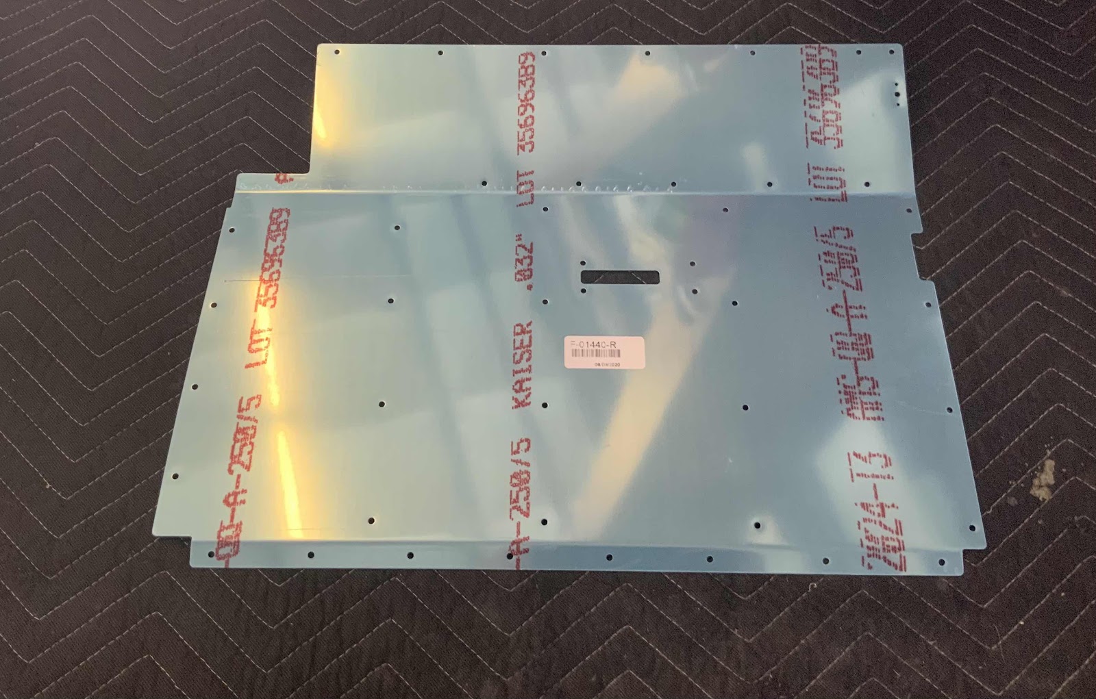
.....the F-01440-R Seat Ramp.....

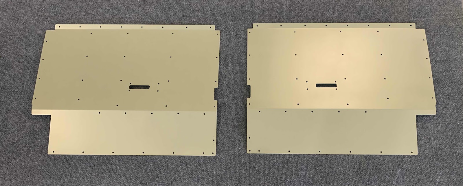
.....and both of the Seat Ramps after being treated with Alumiprep, Alodine and Akzo Primer.

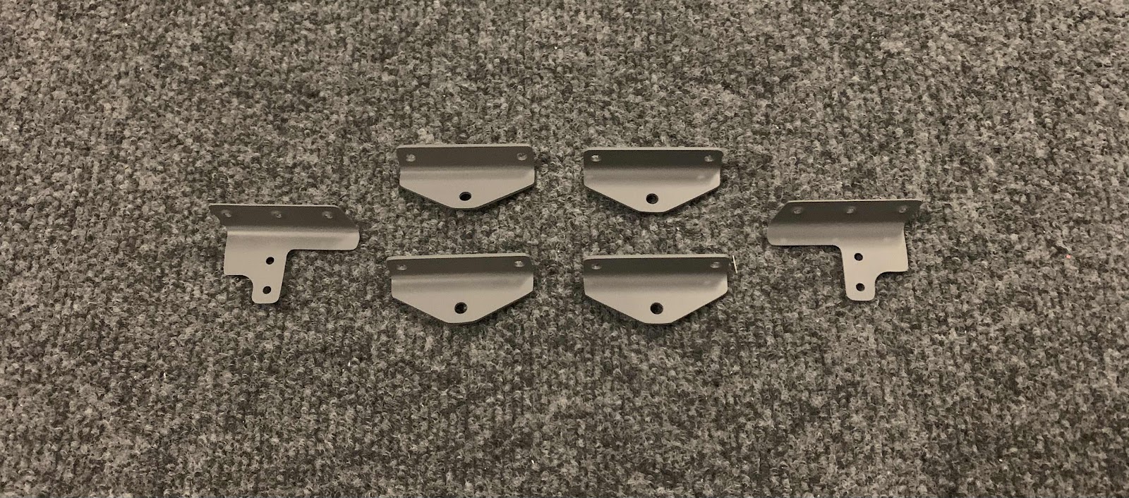
This is the F-01436-R Control Column Cover.....

.....F-01436-L Control Column Cover.....

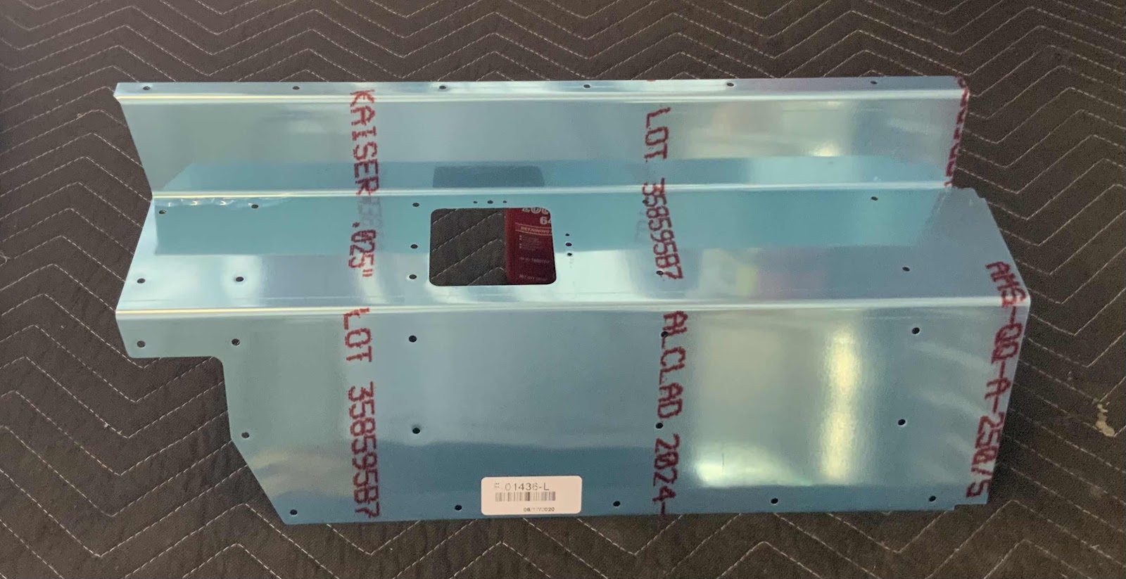
.....and both Control Column Covers after being treated with Alumiprep, Alodine and Akzo Primer.

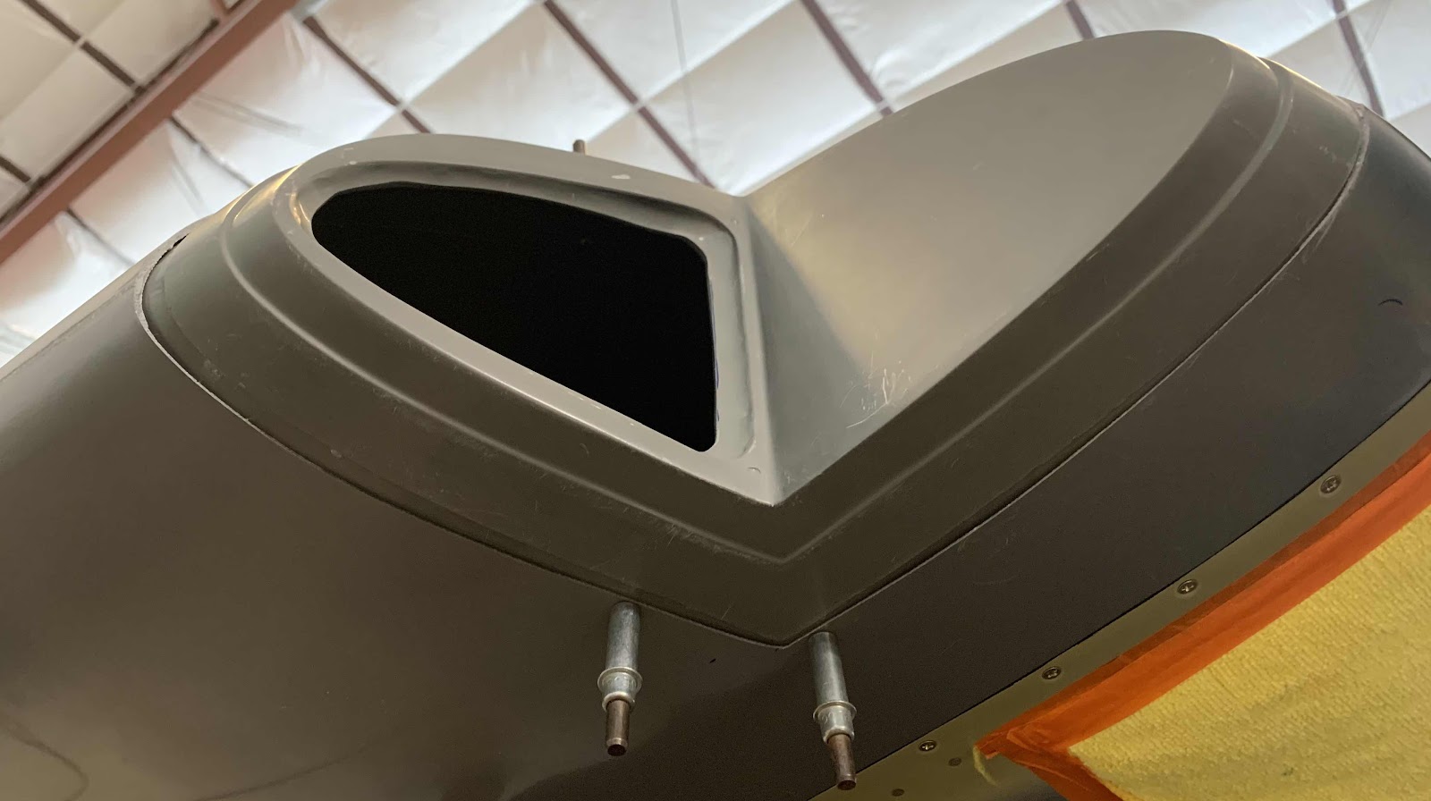
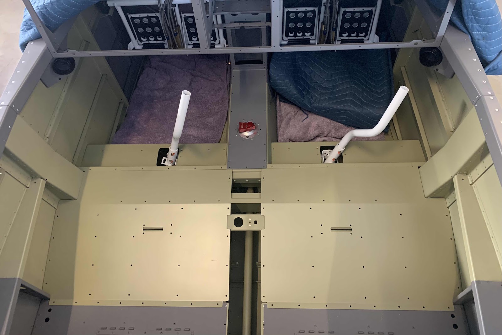
Just a little personal motivation.....here are the Control Column Covers and Seat Ramps sitting in place in the cockpit.

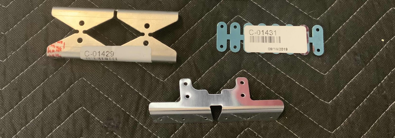
Lastly, these parts actually should have been included in the Canopy and Window section, but it’s only a couple parts and they were completed very quickly.....so, I included it in this post.  These parts have been treated with Alumiprep, Alodine and Akzo Primer.

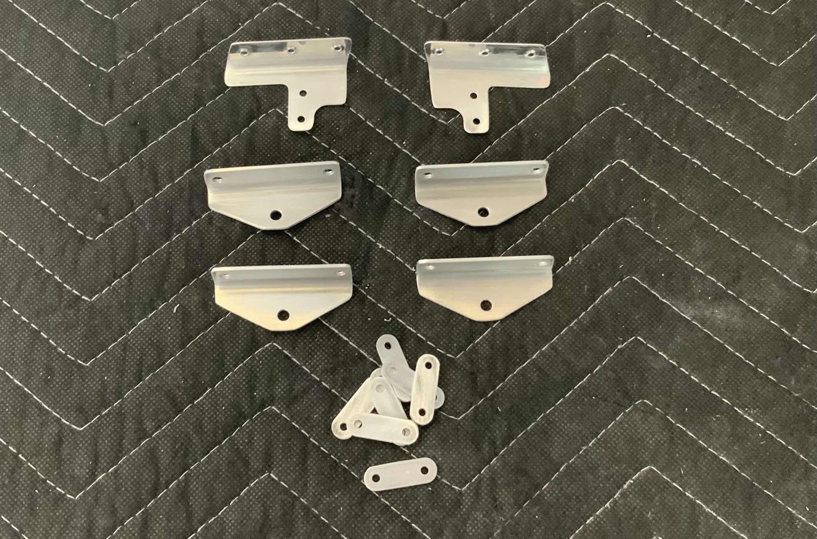
C-01413 Inboard Hinge Intercoastal (top two on the left)
C-01414 Outboard Hinge Intercoastal (top two on the right)
C-01429 Latch Bellcrank Angles (four in a row)
F-01474A-L & -R Stiffener Angles (bottom two)

Lastly for this session, I painted the Latch Bellcrank Angles and Stiffener Angles the same grey color as the remainder of the interior.

Thursday, October 29, 2020

Finishing, Canopy and Window (Part 1)


The first step in this section is to install the rear baggage Window.  I believe that will require two people to accomplish correctly and not damage the Window.  My Stepdad and I are working out the details for him to come visit and help with the airplane.  That is when I will plan to complete as much of the Window work as possible.  So, until then.....

To start this session, I cleaned the edges and deburred the holes on the two C-01413 Inboard Hinge Intercoastals, two C-01414 Outboard Hinge Intercoastals and the two C-01412 Canopy Hinge Assemblies.  They are ready to be treated with Alumiprep, Alodine and Akzo Primer.

This weird looking piece makes three parts.....the C-01404-L & R Support Flanges and C-01404A Support Flange Splice.

I used my rotary tool to separate the parts as shown below.

Here are the three parts all cleaned and prepared for Alumiprep, Alodine and Akzo Primer.

The next part to be prepared is the C-01406 Forward Canopy Rails.  At first look, the part looks a little busy.  So, I decided to use a sharpie to “connect the dots” on where I was supposed to cut.  The top portion is how it came from Van’s and the bottom portion is with the traced lines....visually easier to follow.

I used my rotary tool and cut off wheel to separate the two parts as shown below.

After cleaning the two pieces up, here is what they look like.

Lastly, for this session, we separated the C-01429 Latch Bellcrank Angles, C-01431 Latch Links, and F-01474A Stiffener Angles.


Here they are separated, cleaned and ready for Alumiprep, Alodine and Akzo Primer.


Finishing, Miscellanea (Part 3)

I was just kinda messing around at the start of the session trying to find some motivation.  So, I decided to rivet together the F-01452 Aft Tunnel Cover and the F-01452A Aft Tunnel Cover Doubler.  I previously primed and painted the two parts, so they were ready to be riveted together and required no additional prep work.  There are eight AN470AD3-3 rivets that hold the pieces together.

Here’s the top.....

.....and the the bottom.

Wednesday, October 28, 2020

Lycoming YIO-390-A3B6 Engine Ordered

On October 15th, 2020 Van’s posted a link on their website regarding Lycoming’s “annual experimental aircraft engine price adjustments” set to take place on November 1, 2020.  Here is the price list from that announcement:
It has always been our intent to install the Lycoming IO-390 (210 hp) engine in our RV (as was used in the original RV-14A prototype by Van’s) .  The actual nomenclature for the engine is the Lycoming YIO-390-A3B6 Standard Experimental Engine (we also decided against the Thunderbolt version).  As you can see from the chart above, our engine model’s price is going to increase a whopping $3,500....WHY?  Apparently, on November 1, 2020 the engine automatically becomes $3,500 MORE awesome or some shit!

So, as the announcement states, we placed our engine order with Van’s PRIOR to November 1st to avoid paying the $3,500 price increase.  The order required a 25% non-refundable down payment and I was able to “request” a delivery date of April 1, 2021.  So, the engine has officially been ordered!!!

Here is the link the engine order form on the Van’s website.

 At one point, we did debate installing the new IO-390-EXP119 engine announced by Van’s on July 22, 2020.  However (as shown in the chart above), the EXP119’s price is $5,700 more than the original IO-390 (the engine we are purchasing).....yeah, that pretty much ended the debate.  That money can definitely be spent elsewhere (we plan to use it for the airplane’s interior).

Here are a few pictures of the IO-390 I took at the Van’s booth at Sun-N-Fun a few years ago.


Hartzell 72” C2YR-1BFP/F7497 Propeller Ordered from Van’s

When we ordered the engine from Van’s, we also ordered the propeller.  Van’s has the following statement on their website: 

“If a new propeller and an Experimental Lycoming engine are ordered at the same time, Van's can offer a special "package" discount on the combination.”

The package deal they mention is a $1,000 dollar discount!!!  So, since we were “motivated” to order the engine before November 1st, we also took advantage of Van’s discount and purchased the propeller at the same time.  Additionally, Hartzell will also have an annual price increase (at some point), so we will save even more money by ordering it now.

Here is the link to the propeller order form on the Van’s website.  Van’s recommends 72” props for the taildraggers and 74” props for the nose wheel models.

So, as the order form recommends, we purchased the 72” C2YR-1BFP/F7497 for the (I)O-360/390 (180 - 210 hp). 

It will look very similar to the prop in the picture below:

Van’s explained that Hartzell charges you the current price of the prop at the time it is SHIPPED, not the time it was ordered (as with the engine).  So, we requested a mid-December delivery date in order to avoid any annual price increases.  It will be like a Christmas present for us!

Monday, October 26, 2020

Finishing Kit Inventory

The inventory for the Finishing Kit is now complete.  This inventory was the shortest of all.....a lot less parts!

This is how it looked after removing the top.

Before it was an awesome crate with airplane parts.....now it’s just an empty box!

All put away and waiting for its turn to get installed on the plane.

This box was taped to the floor and also had lots of parts inside.

Big bag of hardware!


Finishing Kit Delivery

BIG DAY!

We ordered the Finishing Kit on May 21, 2020 and after five months and five days, it FINALLY arrived.  The delay is not really Van’s fault.  Everyone is dealing with the Rona and they also had to deal with the wildfires.  Glad the kit (crate) arrived in one piece and with not damage.


Time to get to work on this kit.......almost there!!

Thursday, October 15, 2020

Wings, Wing Tip (Part 13)

With the steps completed in Part 12, it’s now time for the final fitting of the Insert into the Wing Tip Fairing.  There are a couple of things I wanted to make sure to accomplish during the final fitting of the Insert:

1. The Insert is equal distance at the forward and aft ends of the nav light “plate” (top and bottom) to the Wing Skin to make sure it’s square to the Wing 
2.  The Insert needed to be at a 90° angle to the Wing Spar (so it’s pointing straight)

So, here is how I accomplished #1.  As the picture below shows, the yellow line is the measurement I wanted to be equal across the top of the nav light mounting “plate”.

The measurement I settled with was 4” and aligned with the 28 mark on top of the ruler (I guess also 56 on the bottom).  The next few pictures shows the measurement taken near the middle of the Insert and working forward along the Wing.


It was kinda difficult to get any pictures from the bottom side of the Wing, but that measurement came in at 27.....so, pretty damn close.  I’m gonna leave it along before I mess it up.  

Now, to get the Insert 90° degrees to the Wing Spar.  To do this, I used a digital level, set it along the Wing Spar and zeroed it as shown below.

Then, moved the level to the nav light mounting “plate” to get a reading.  After some manipulating (and ensuring to maintain the previous measurements), I achieved the 90° degrees I was looking for.

As the correct alignment and measurements were achieved, I drilled pilot holes and inserted clecos to keep everything in place.


Now, a couple of things still need to be done and I’m debating how I want to do them.  First, the hole I already cut out for the AeroSun VX landing light still needs to be enlarged to accept the actual light itself.  So, I’m thinking I will remove the Insert to complete that step in the instructions (probably easier to handle from both sides of the hole).    Secondly, we need to install the mounting plate for the navigation/strobe light.  I think I will also complete this step with the Insert removed from the Fairing (since I just ensured the Insert mounting “plate” is 90° to the Spar and square to the Wing).

Here is what I’m going to use.....West System 105 epoxy resin and 206 slow hardener (forget about the milled fibers for now).  Now, I will admit, I am brand new to fiberglass work and really have no idea what I’m doing.  So, I need to do some additional research and seek additional guidance prior to doing any of this, so.......

more to follow!