This blog was created to memorialize the building process of my Van's Aircraft RV-14 and to satisfy the requirements for certification in the Experimental Amateur Built Aircraft category. It will also serve as a central location for ME to reference in the future on processes and techniques I used during the build. Additionally, it will allow my family, friends, and other interested builders the opportunity to follow along during my build…..and might be helpful to someone along the way.
Now that the Top Inboard Wing Skin, Top Outboard Wing Skin, and the two Wing Walk Doublers have been prepared, it’s time to treat them with Alumiprep, Alodine and Akzo primer.
During today’s session, I treated all four pieces with Alumiprep and Alodine and hung them up to dry. Tomorrow, I will prime all four pieces and they will be ready to rivet into place on the Left Wing.
I will post pictures of the completed parts tomorrow.
I completed the Top Inboard Wing Skin and the two Wing Walk Doublers during the last session. During this session, I completed the work on the Top Outboard Wing Skin. All of the edges were cleaned and the holes were deburred and dimpled. Then, I clecoed the Outboard Wing Skin to the Left Wing.
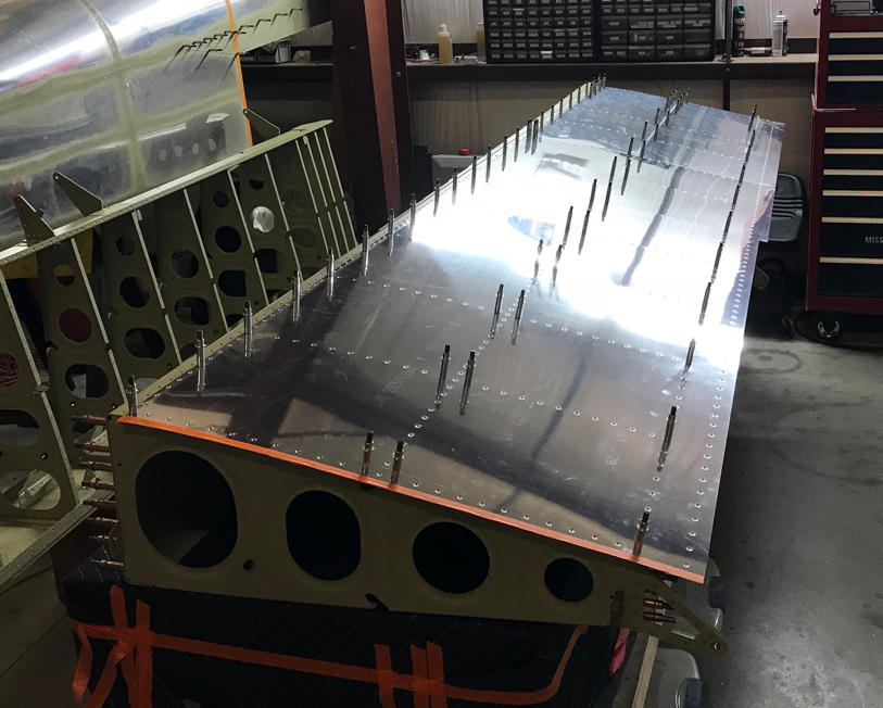
Here is the Top Outboard and Inboard Wing Skins clecoed into place on the Left Wing.
As I suspected, the “slight” bend in the Left Main Spar has been removed after the Skins were clecoed into place.
This is just another view of both Wing Skins clecoed to the Left Wing. The orange tape covers the holes associated with the Wing Tip attach and are not dimpled.....at least in this section. I put the tape on the holes to prevent me from accidentally dimpling them.
During the next session, I will treat the Skins with Alumiprep and Alodine. Once the Skins have completely dried, I’ll prime them with Akzo.
Today is another one of those “lots of work with very little to show for it” kind of days. The picture below shows the Wing Walk Doublers (FWD and AFT) after they were prepared. The edges were cleaned and all the holes were deburred. Because these Doublers will go between the Top Inboard Skin and Wing Ribs, these holes DO NOT get dimpled. The two pieces are now ready for Alumiprep, Alodine, and Akzo Primer.
Here is the W-00002 Top Inboard Wing Skin. All the edges have been cleaned, holes deburred, and the holes were deburred (that weren’t previously countersunk). This Skin is now ready for Alumiprep, Alodine, and Akzo Primer.
There are a couple of things to notice in this picture. First, the top left edge shows the area that I removed material from yesterday. Second, you can see an example of some of the holes after being dimpled. Lastly, if you look between the dimpled holes, you can see the slight bend (lap joint) I made in the leading edge of the Skin. As you know, the lap joint will allow the Skins to fit tighter against the Main Spar (in this case) when it is riveted.
I will post pictures of the Outboard Top Skin when I finish preparing it, but I was able to make a lot of progress on it today. During today’s session, I was able to complete the hole deburring and lap joints. I still need to finish cleaning the edges and dimple the holes.
I started today’s session by finishing the countersinking on the Top Inboard Skin (FWD-Wing Walk) area. The four vertical rows of holes on the right side of the Skin have now all been countersunk and according to the guage, are .005 too shallow as recommended in the plans. The three horizontal rows of holes (top, middle, and bottom of the Skin) will all get dimpled in the next few steps. On the far right side of the Skin, there will be seven nutplates attached on the underside of the Skin. The rivet attach holes for these nutplates were also countersunk for the head of a AN426AD3-4 flush rivet. Lastly, the #19 holes (for the #8 screws) will also be countersunk in a future step.
The plans state, “remove material thickness from the top outboard forward edge of the W-00002 Top Inboard Wing Skin and the bottom inboard forward edge of the W-00003 Top Outboard Wing Skin”. Below is the figure referenced in the plans:
Since I’m a visual dude, I wanted to see how the two Skins fit together in this area before I started removing anything, much less material. So, I temporary clecoed the Top Outboard Wing Skin to the Left Wing. In the two pictures below, the Top Outboard Wing Skin still has the blue plastic protective coating. I did notice that some of the holes between the Skins and the Wing Ribs did not “exactly” match up. Upon further inspection, I determined the Main Spar still has a “slight” bend in it. I suspect this bend will be removed when all the Skins are clecoed on and the rivets are installed.
Here is a close up of where the Top Inboard Skin (on bottom, .032 thick) and the Top Outboard Skin (on top, .025 thick) overlap. Those two Skins together have a thickness of .057. The “problem” that exists is the Tank Skin (which mounts right in front of the overlap) is .032.
So, the Skins aren’t “even” in this area. This is why some material has to be removed as described above. So, I made a small gauge that is .032 to match the thickness of the Tank Skins. The first picture below is the Skins BEFORE I removed any material.....
.....and here is the AFTER. This took ALOT longer than it probably should have, but I “had” to make it better.....it’s a disease! I started by using 220 grit sandpaper to get the pattern I wanted. Then I used a hand file to remove most of the material. Finally, I used various grits of sandpaper (80, 120, 220) to get the final result that I wanted. I CAN’T WAIT TO DO THE OTHER SIDE!
This is the two rows of holes that the Skins will share when riveted together. The row on the left will also be riveted to the Wing Rib below it. The row on the right, best I can tell, will only have the two skins riveted together (minus the Spars and J-Stiffeners).
There are only a couple of steps left before the Skins get treated with Alumiprep, Alodine, and are Akzo primed. I still need to do the edge work on the Skins, dimple the Skins, dimple the top flanges of the Wing Ribs, and dimple the Wing Box J-Stiffeners. Since I just did all the sanding on the area where the Skins overlap, I am OVER sanding right now. So, I’m going to start by dimpling the Wing Ribs (except Ribs #1 - #4–Wing Walk Doublers will go there). In the picture below, the Wing Rib on the right has been dimpled with my Substructure Dimple Dies. The two Wing Ribs next to it have not been dimpled yet. If you look close to the holes in the right Wing Rib, you can see the Akzo primer flaking off after the dimpling was completed. Earlier in the build, the plans recommended priming at a certain point.....which was just prior to the Wing Ribs being riveted it the Main Spar. However, at that time, only the lower holes were dimpled in the Wing Ribs. I suspected when I reached the step to dimple the top holes, the primer would flake off. I will use a nylon brush to brush off the flaked primer and touch up the holes prior to riveting on the Skins.
It’s been a few days since I worked on the plane, but I’m back at it. The four vertical row of clecos will have to have the rivet holes countersunk. This area included the Top Inboard Skin, Wing Walk Doubler-AFT, and Wing Walk Doubler-FWD. The Top Inboard Skin is only .032, so the plans caution not to countersink two deeply. Additionally, under the three pieces mentioned above, is the Flanges of Wing Ribs #1 - #4. So the material is relatively thick considering....if you combined them together. But regardless, you have to be careful.
As I mentioned above, because the Inboard Top Skin is only .032 thick, the plans state that “under” countersinking by .005 is acceptable and a preferred method. As a result, the AN426AD3 rivets will not sit completely flush with the Skin. However, that is not a very big deal in this location. There will be wing walk affixed to this area once the plane is complete and will “hide” the slightly proud rivet heads. Below, you can see the .005 gauge I used to measure the depth of the countersink. The rivet is NOT set, but just sitting in the whole and used to show the comparison with the gauge.
To get the correct “undersink”??, I used my countersink cutter (with a #40 cutter) to make the countersink. I then held a 6” ruler vertically on top of the rivet head. Finally, I used the .005 gauge to check the gap between the bottom of the ruler and the top of the Skin. This worked out pretty well for what I was doing. I also used a razor blade in the same fashion as the ruler. Either seemed to worked great.
Kind of hard to see, but here is a picture of the very first countersink I made.
I have completed the countersinks required in the Top Skin that sits over the Wing Walk-FWD section. I will complete the Wing Walk-AFT section tomorrow and continue with the steps in the plans.
Last night I clecoed the Wing Walk Doublers and Inboard Top Skin to the Wing assembly. Today, the real work starts. To begin, I match drilled #40 the rivet holes for the nutplates that will be installed along the inboard edge of the Inboard Top Skin. As shown in the picture below, there are eight locations that various types of nutplates will be installed.
Next, all the #40 holes common to the top Inboard Wing Skin, Wing Walk-FWD, and Wing Walk-AFT were final-drilled. Now, the screw holes for the nutplates were final-drilled to #19. In the picture below, I circled two nutplate locations. The plans caution to make sure you drill one particular #19 hole in the right location . The nutplate on the right is a single leg nutplate and the #8 screw will eventually be installed on the far right of the three holes. The remaining seven nutplate locations, like the one circled on the left, will use regular nutplates and the #8 screw will be installed in the center hole. I will post a picture of the three different nutplates used in this location when they are installed.
On the bottom right in the picture below, is the AFT most nutplate attach hole. In this picture, the hole has already been dimpled for a #8 screw. Prior to dimpling, this hole also had to be final-drilled to #19. However, it does not have any material underneath the Skin. So, I put a piece wood under the Skin and drilled the hole into the wood. The plans caution that holes dimpled to accept #8 screws tend to crack if you are not cautious with the deburring. After dimpling, I can’t see any cracks.....guess I was cautious!
Moving on.....the next step is to countersink all of the holes common to the Inboard Top Skin and Wing Walk Doublers. The plans caution not to countersink the holes to deeply and state that a countersink that is .005” proud of the Skin is acceptable. Unfortunately, I have to stop work here for tonight because my gauge only goes to .012”. So, I’ll have to get a proper gauge and continue tomorrow.
After completing Section 15, guess what? I moved on to Section 16! Section 16 is the preparation and attachment of the Top Wing Skins. As I’ve done up to this point (and will continue to do until the Wings are completed), I will complete Section 16 for the Left Wing and then do the same for the Right Wing. Below are the first three pieces that are prepared in this section. The W-00002 Top Inboard Wing Skin, W-1027A Wing Walk Doubler-FWD, and W-1027B Wing Walk Doubler-AFT.
The first step in this section is to cleco the Top Skin and two Wing Walk Doublers to the Main Spar, Rear Spar, and Wing Ribs. It took a few minutes to get the Wing Walk Doublers lined up under the Top Inboard Skin because you can’t really see the holes. However, I eventually figured it out and got the pieces clecoed as instructed.
As you recall from my last post, I started the Rear Spar riveting process last night. During today’s session, I finished installing all the remaining rivets. The first picture shows the completed Rear Spar Reinforcement Fork and Rear Spar Doubler Plate riveted to the Rear Spar and Wing Ribs. A combination of AN470AD4-6, AN470AD4-8, and AN426AD4-8 rivets were used in this location.
This picture shows the completed Rear Spar Doubler Plate (Inboard), Rear Spar Doubler Plate (Outboard), and Aileron Hinge Bracket Assembly riveted to the Rear Spar and Wing Ribs. A combination of AN470AD4-4, AN470AD4-5, AN470AD4-8, and AN470AD4-9 rivets were used in this location. This installation also completes (complies with) Service Bulletin 16-03-28. SB-16-03-28 was issued for “cracking of the wing aft spar web at the inboard aileron hinge bracket attach rivets”. The appropriate materials and instructions were supplied with the Wing Kit when I originally ordered it from Van’s.
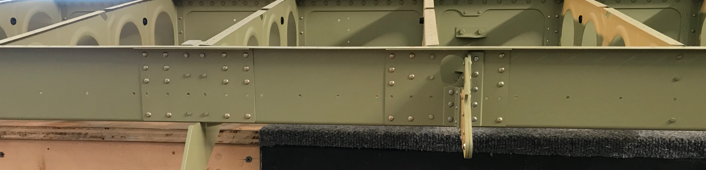
There were two small addtional steps required for me to completely finish Seciton 14. First, I had to install 14 (7 on the Upper and Lower Main Spar Flanges) AN426AD3-3.5 rivets. Here is an example of three of the rivets installed. All 14 of the rivets are “in-line” with where the fuel tanks will attach to the Main Spar. I suspect the Fuel Tank Skins will cover these rivet locations after installation.
Secondly, the six AN470AD4-4 rivets had to be installed that attach the Torque Tube Support Bracket Assembly to the web of the #1 Wing Rib.
I continued riveting the Rear Spar during this session.....specifically, the Rear Spar Reinforcement Fork. Here you can see the 48 AN470AD4-6 rivets I set tonight. If you look closely, you’ll see a few rivets are facing the opposite direction. I tried to stick with putting the manufactured head on the side with the thinnest material. So, where the Wing Ribs are attached to the Spar, I put the manufactured head on the Wing Rib Side. For the remaining holes, I put the manufactured head on the Reinforcement Fork. (I used the same process on the Left Wing)
This might not be the most cosmetically pleasing method, but that is the way I decided to install these rivets. I ultimately think I got a better end result, so I’m happy with it. Previously, on the Left Wing, I tried installing a few rivets with the shop head on the thinnest material side.....it bowed or “cupped” the material. I obviously didn’t like that, so I reversed the rivet and got a much better result.
Tomorrow, I will continue riveting the Rear Spar and HOPEFULLY complete Section 15.
This work was completed on Thursday, February 15th. I missed the midnight deadline for posting.....
I completed the Akzo priming of the Rear Spar Reinforcement Fork and the Rear Spar Doubler Plate. Both pieces were then clecoed into place as shown below:
Now, it’s time to install some rivets! As with the Left Wing, the Right Wing will get the same number and size of rivets. The Wing Rib to Rear Spar locations will get AN470AD4-4 universal rivets. As an example, here are Wing Ribs #6 and #7 after being riveted to the Rear Spar. As a reminder, the horizontal row of holes will be used in a later section to attach the gap seals.
Here are the rivets installed in the Rear Spar Doubler Plate and Rear Spar.....which is also used in the installation of the Outboard Aileron Hinge Bracket. The Aileron Hinge Bracket will be riveted to the Spar and Wing Rib #14 later in the build.
All of the AN470AD4-4 rivets have now been installed on the Rear Spar. Here is the Rear Spar Doubler (Outboard) and the Inboard Aileron Hinge Bracket. You can see I had a little bit of primer run on the right side of the Doubler.....Oops, my bad!
Rear Spar Doubler (Inboard).....
And the lone AN470AD4-4 rivet (between the clecos) installed on Wing Rib #5 and the Rear Spar.
Tomorrow, I will move on to the other sizes of rivets and hopefully finish this section.
Well, I haven’t posted anything since January 30, but I have definitely been making SMALL steps forward. I’ve been busy with work the past few weeks and was only able to devote several shorter work sessions, which really didn’t warrant a blog post. For example....dimpling the Upper and Lower Flanges of the Rear Spar.
So, like a few posts in the past, I will summarize all the work sessions I’ve completed into this one post and catch up the blog.
So, here goes...
For the most part, all the steps completed on the Left Wing have to be completed on the Right Wing. (One difference that comes to mind between the two wings is the size/location of the Snap Bushings in the Wing Ribs). Pictured below is the Rear Spar Doubler Plate and the Rear Spar Reinforcement Fork clecoed together with 24 clecoed. Previously, the Rear Spar Attach Holes on both parts were Final-Drilled to 11/32. Now, this hole must be reamed to 3/8. Jeff helped me again and we used the drill press to complete this step. The plans state this is a critical hole, so the drill press make the best possible result.
Pictured below are the three Rear Spar Doubler Plates and one of the Aileron Attach Brackets (from the SB) after being Akzo primed. NOW, I have a confession to make! The holes in the Upper Flanges of the three Doubler Plates (16 total) and the corresponding holes in the Upper Flange of the Rear Spar are supposed to be machine-countersunk. They ARE machine countersunk in the Left Wing; however, I mistakenly dimpled the holes in the Rear Spar Upper Flange instead of countersinking. As a result, the holes in the Upper Flanges of the Doubler Plates also had to be countersunk. This is NOT the biggest problem in the world, but a deviation from the plans nonetheless. With the dimples, the Doubler Plates nest under the Rear Spar very well, but will be slightly different from the opposite Wing (which were countersunk). I will probably call Van’s to confirm there is no issue with the dimples versus the countersunk, but I’m thinking it’s okay.
Additionally, the Right Rear Spar was also Akzo primed. Below are several pictures showing the Rear Spar, Rear Spar Doubler Plates, and Aileron Hinge Brackets clecoed to the Wing Ribs.
I have treated the Rear Spar Reinforcement Fork and Rear Spar Doubler Plate with Alumiprep and Alodine. However, while Akzo priming the other parts the other day, I forgot to spray these two pieces. So, they will receive Akzo primer during the next session and the two pieces will be attached to the Rear Spar where all the open holes are located below.
Lastly, the Aileron Torque Tube Assembly still needs to be riveted to the #1 Wing Rib. The six AN470AD4-4 universal rivets will be installed where you see the six clecos.
That should catch up the blog. It doesn’t really look like a lot of work was completed, but as other builders know, there is a lot of prep work that must be completed prior to assembly. All of the prep work has now been completed, so I will start setting rivets during the next session.