Monday, March 30, 2020

Fuselage, Upper FWD Fuselage (Part 10)

LOTS AND LOTS of work completed during this session.  All the parts that were primed in Part 9 and primed/assembled in Parts 4 & 5 get assembled and riveted together.  

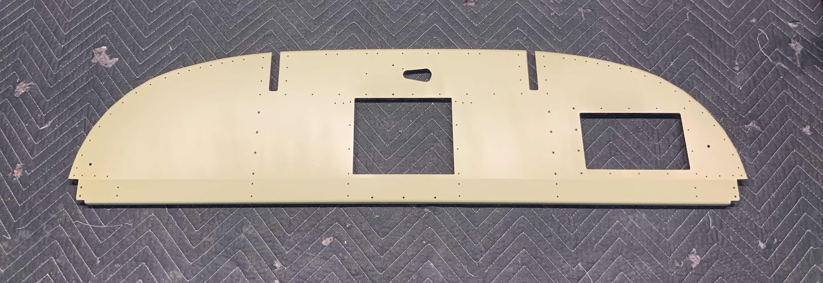
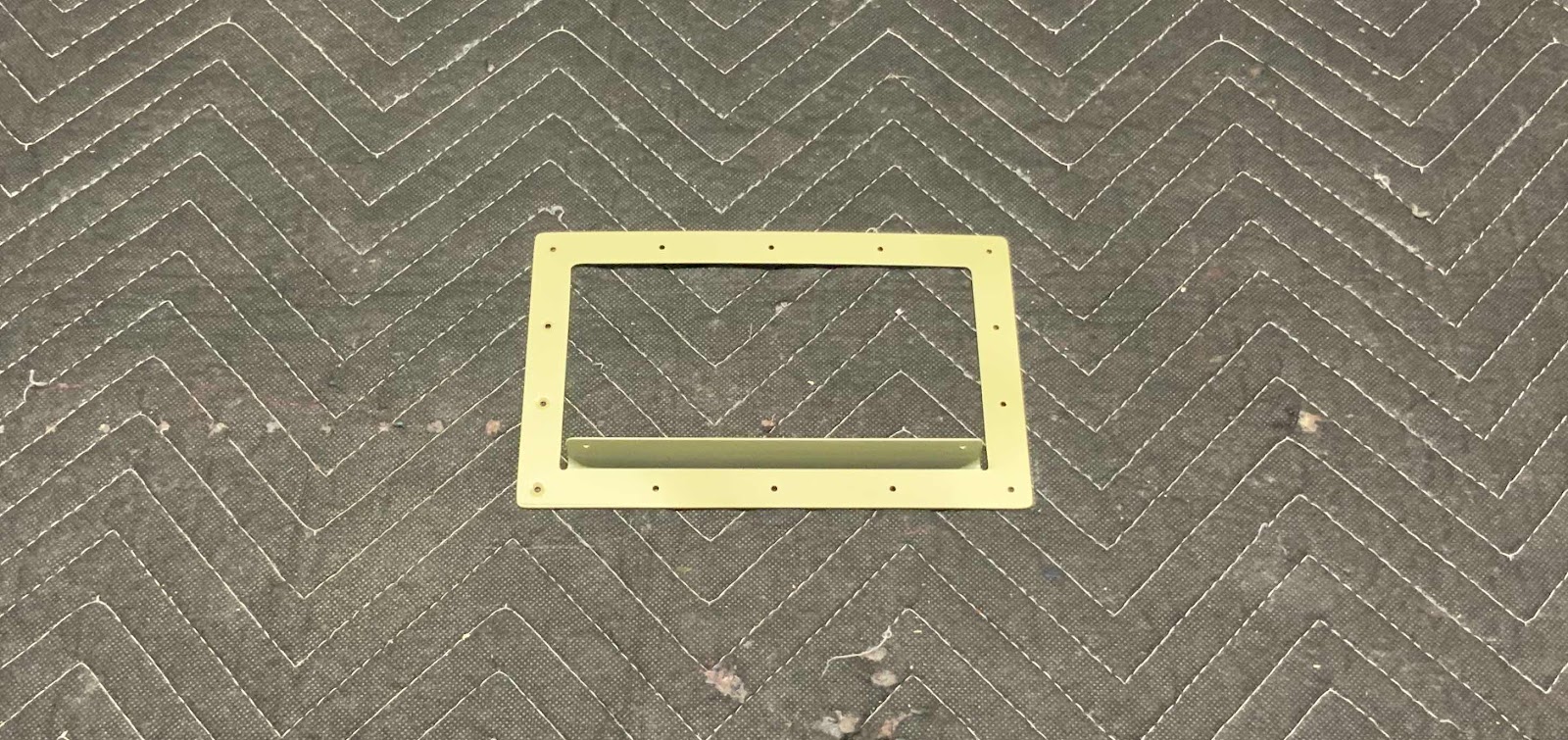
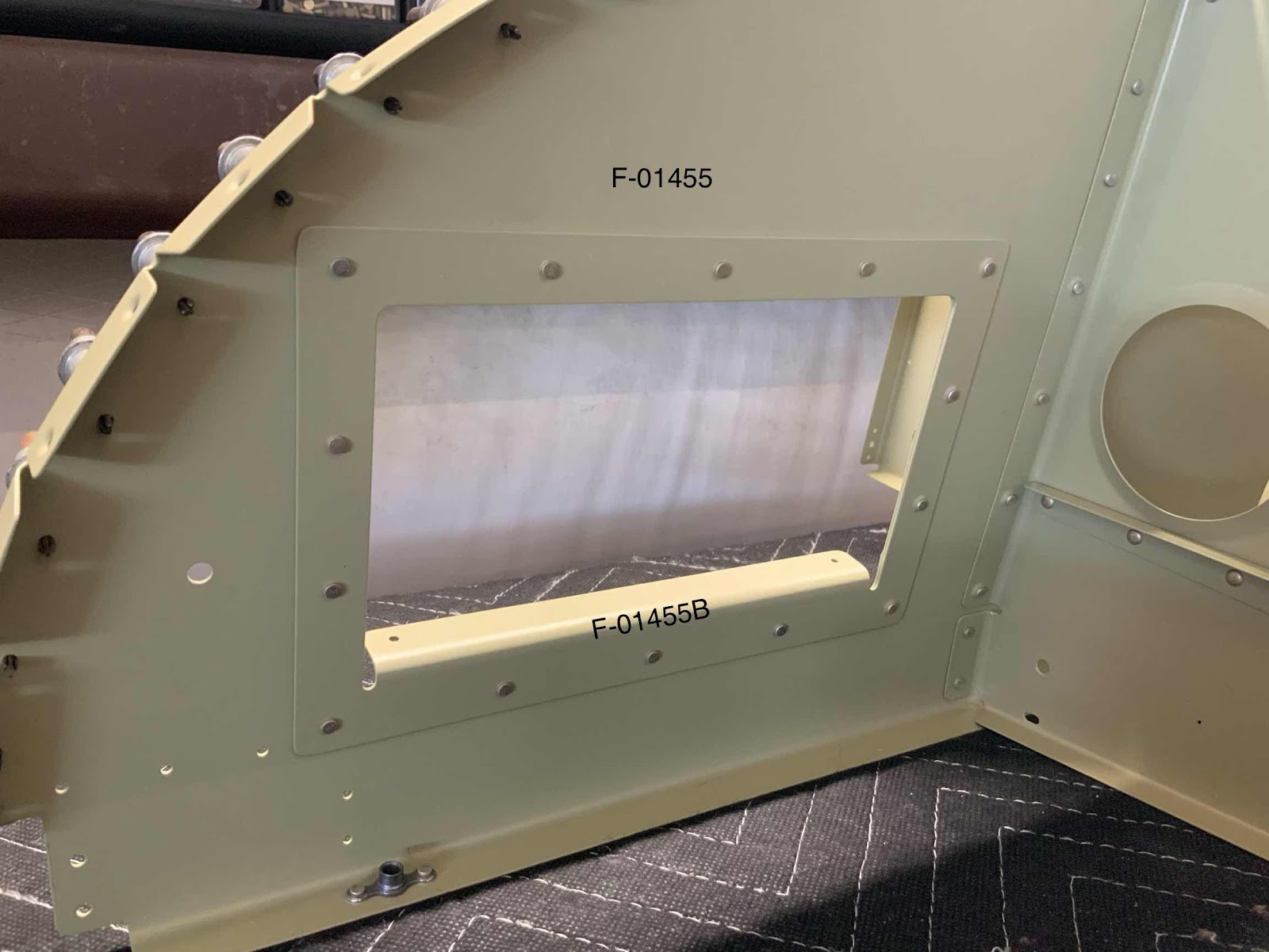
To get the session going, the F-01455B Map Box Doubler was riveted to the F-01455 Sub Panel using 10 AN470AD3-3.5 and four AN426AD3-3.5 rivets.  These rivets were very easy to install with a hand squeezer.

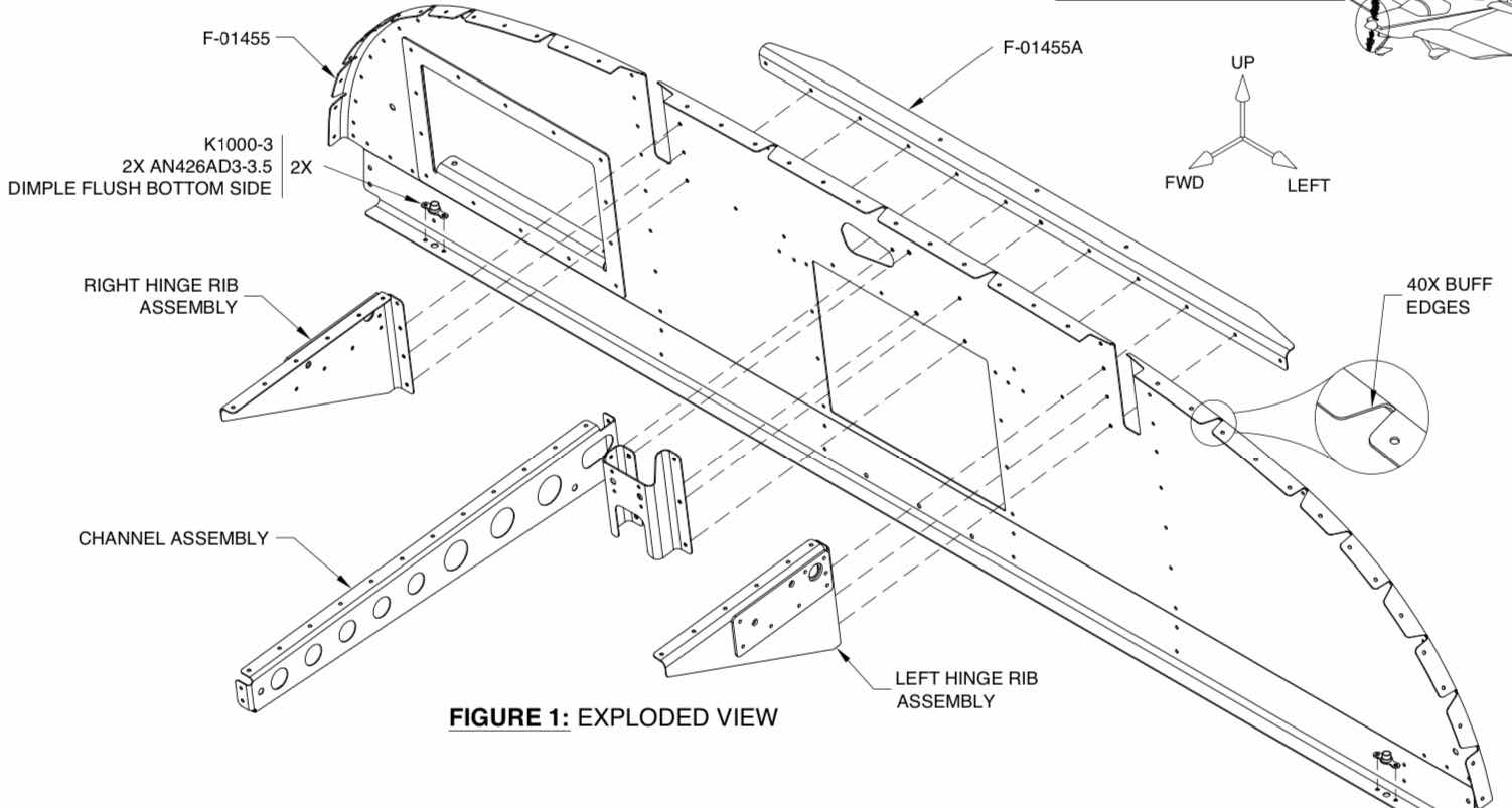
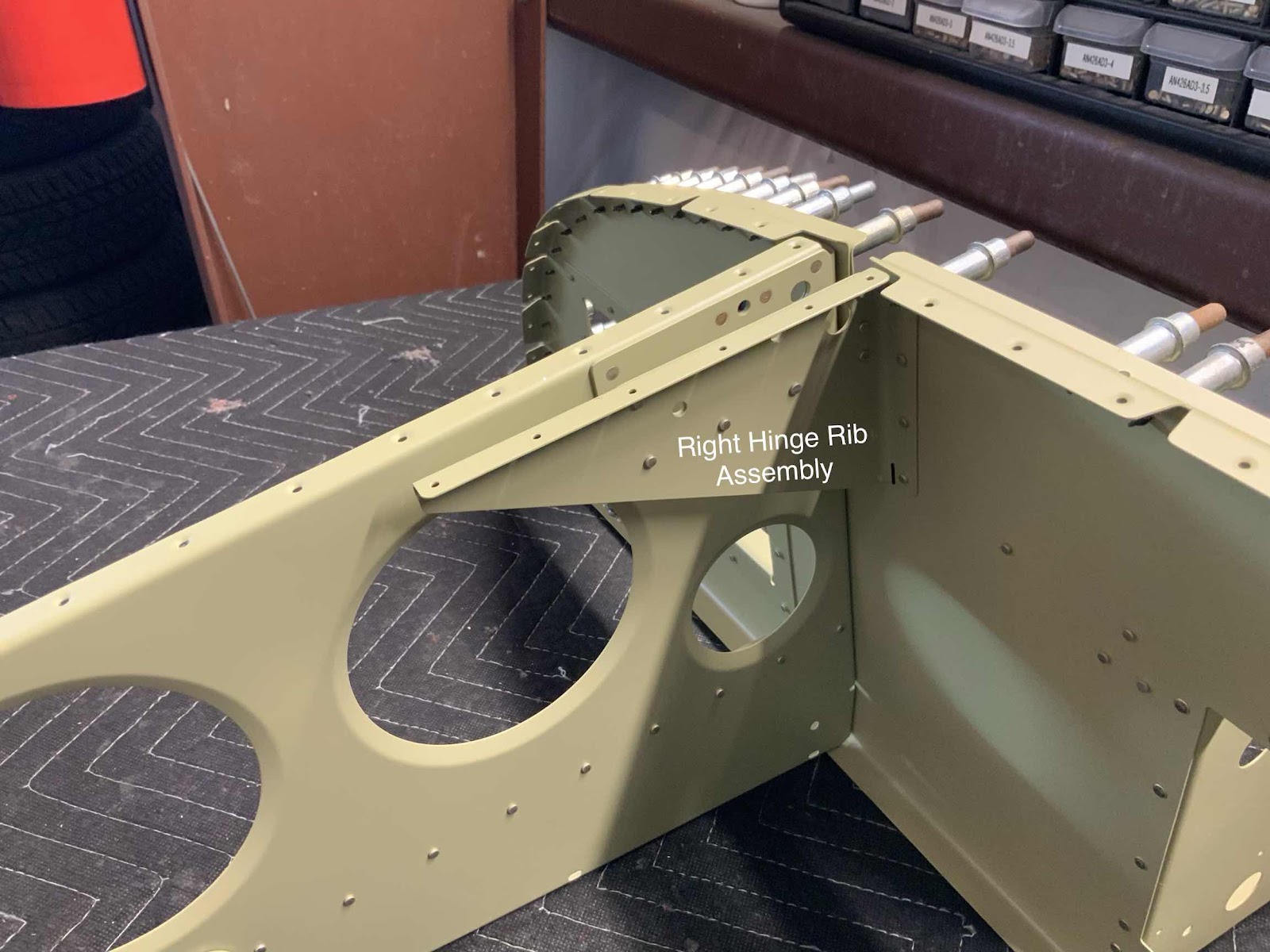
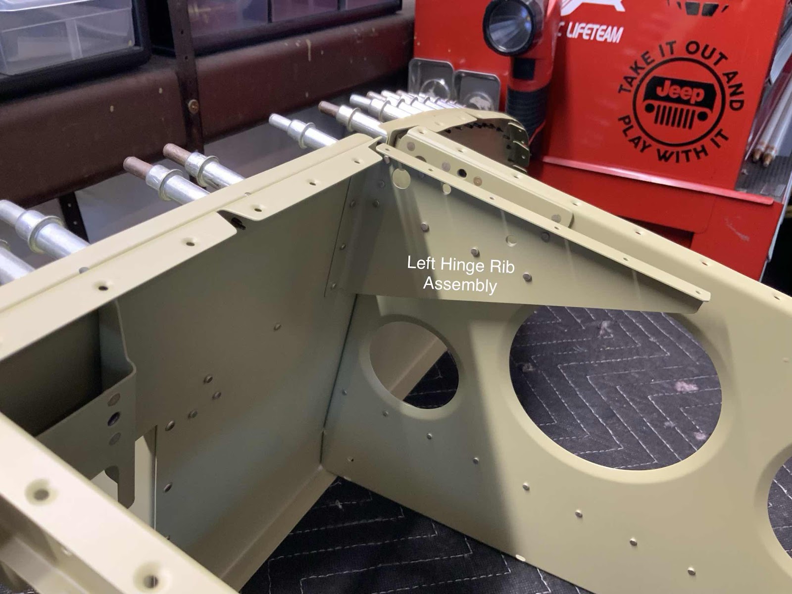
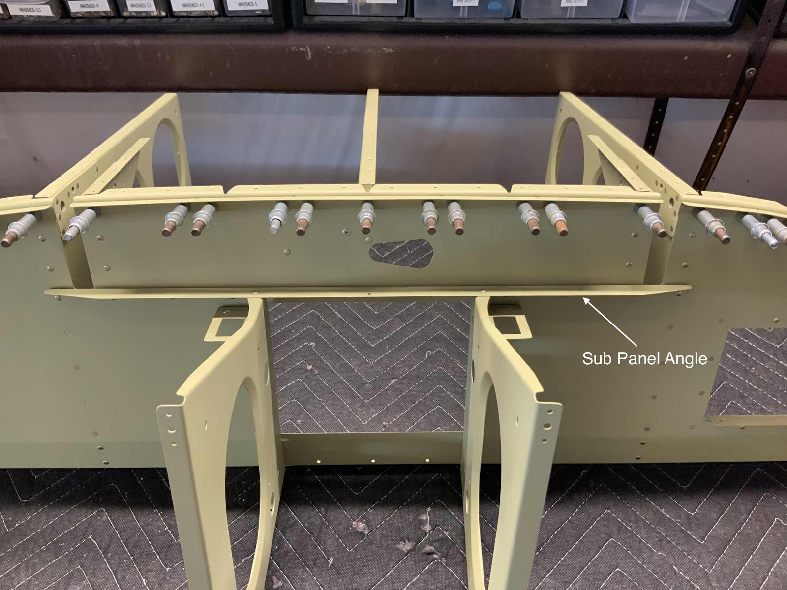
The next parts to get installed to the Sub Panel is the Left Hinge Rib Assembly, the Right Hinge Rib Assembly, the Channel Assembly, and the F-01455A Sub Panel Angle.  Here is the excerpt from the plans showing the installation.....


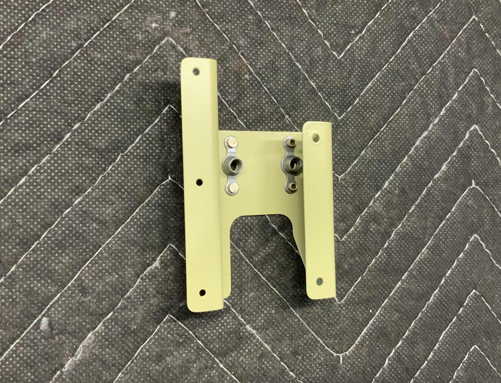
.....and on the plane.  The Channel Assembly.....


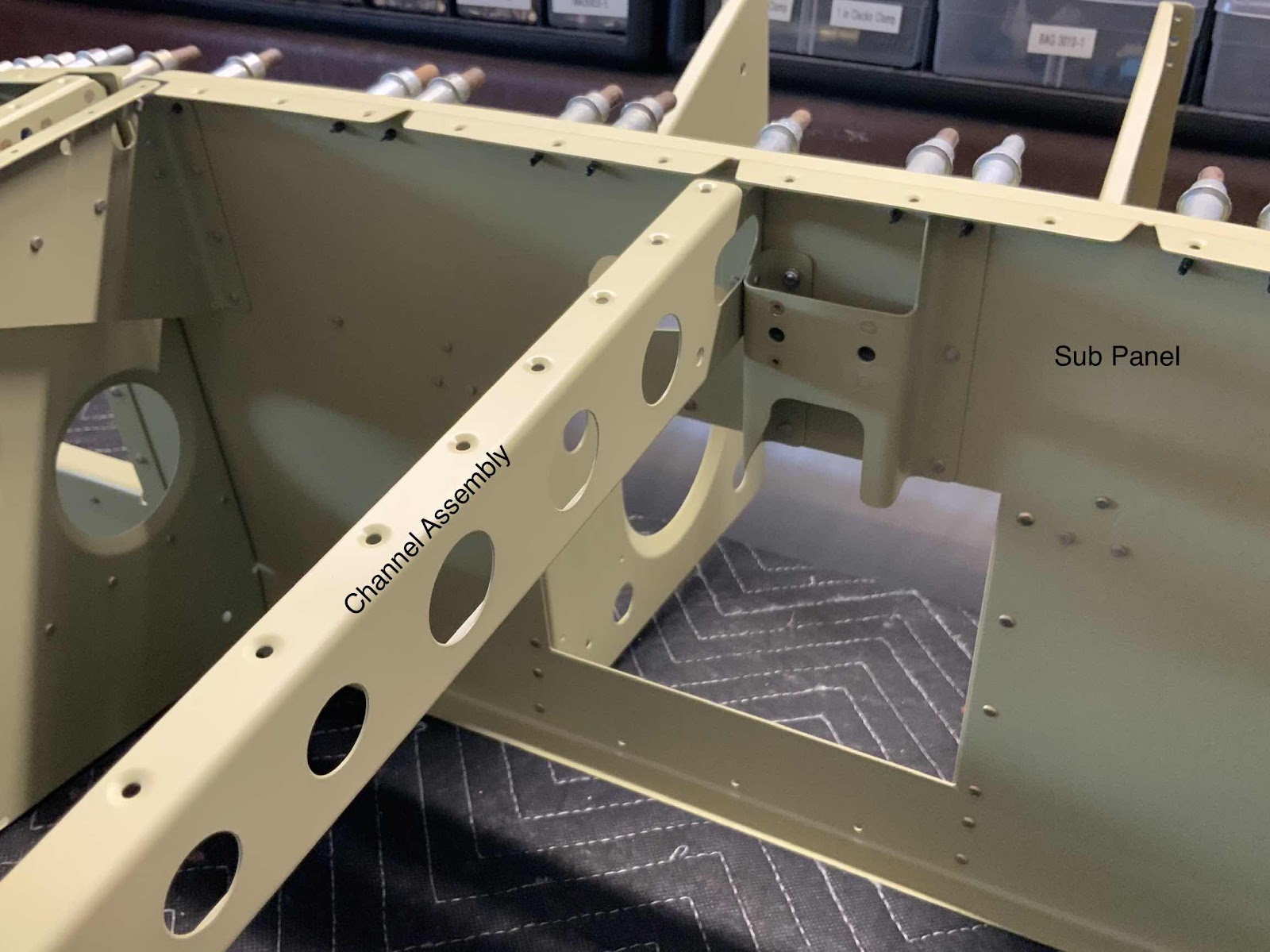
.....the Right Hinge Rib Assembly.....


.....the Left Hinge Rib Assembly.....


.....and the Sub Panel Angle.


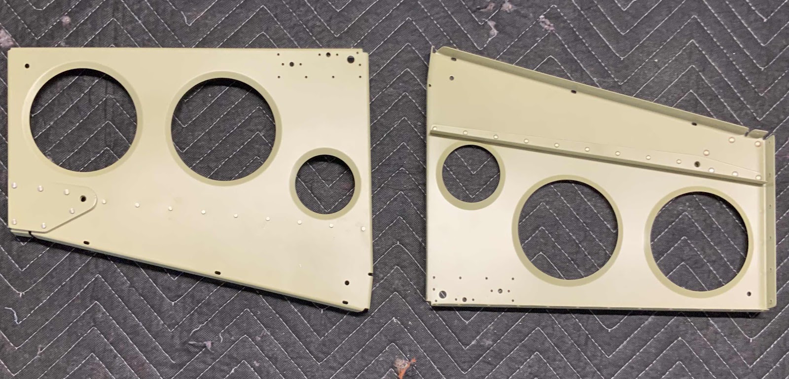
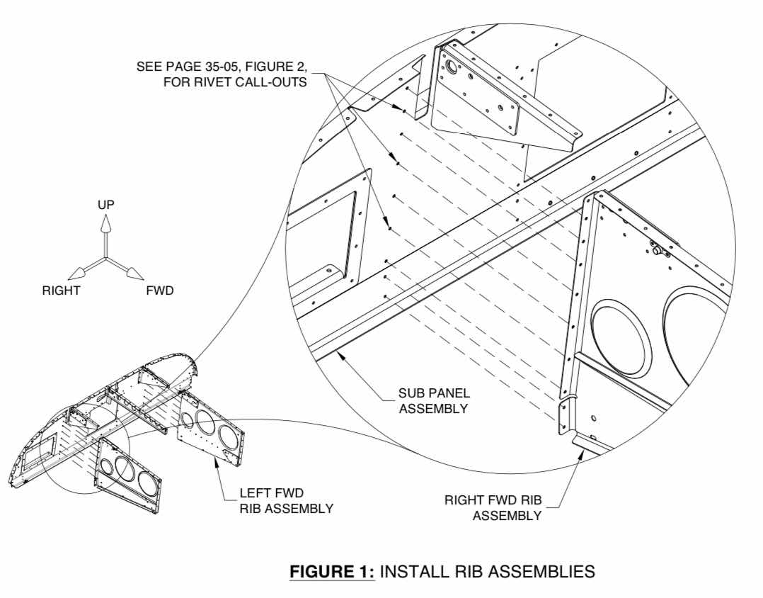
The Left and Right Forward Rib Assemblies are the next parts riveted to the Sub Panel.  Here is a blow up of the installation from the plans.....


.....and on the plane.  Here is the Left FWD Rib Assembly.....


.....and the Right FWD Rib Assembly.


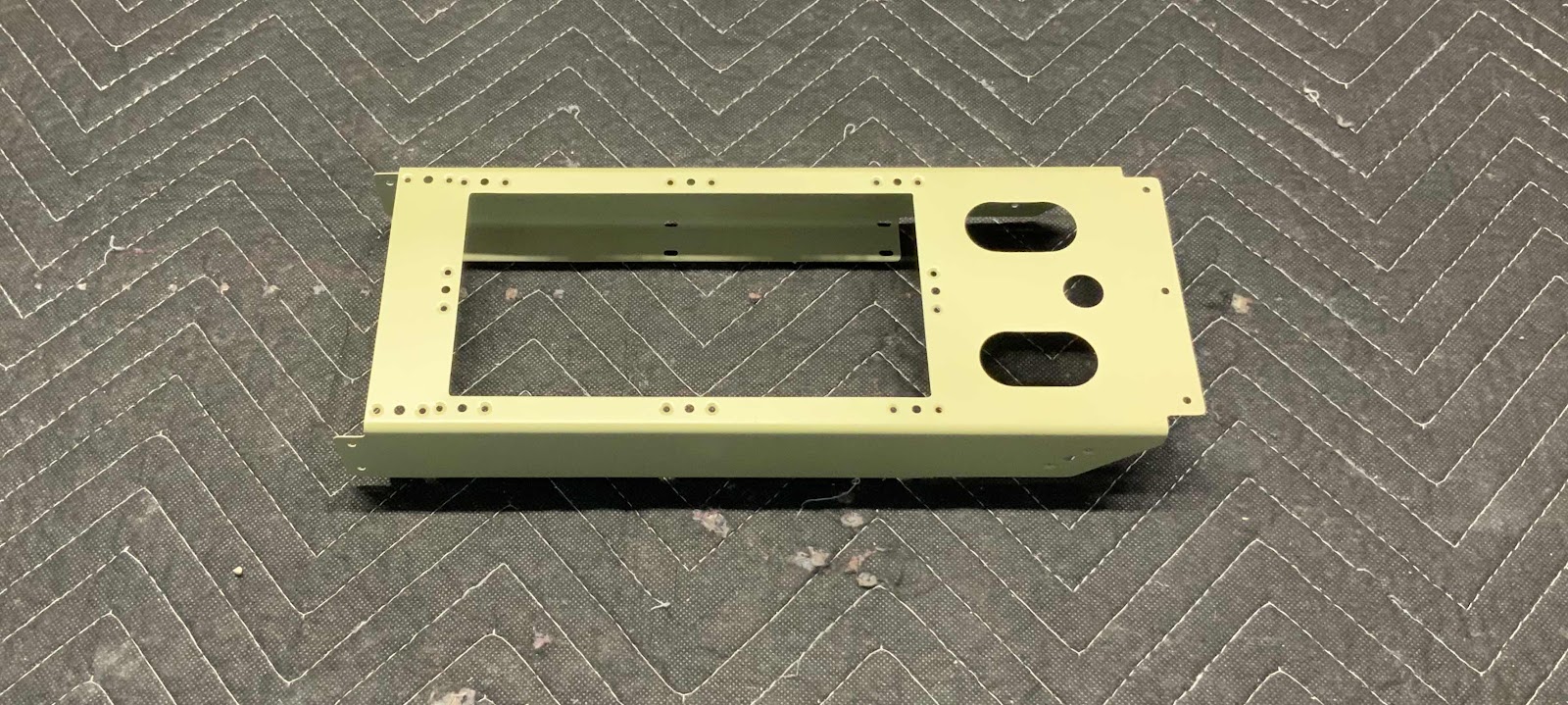
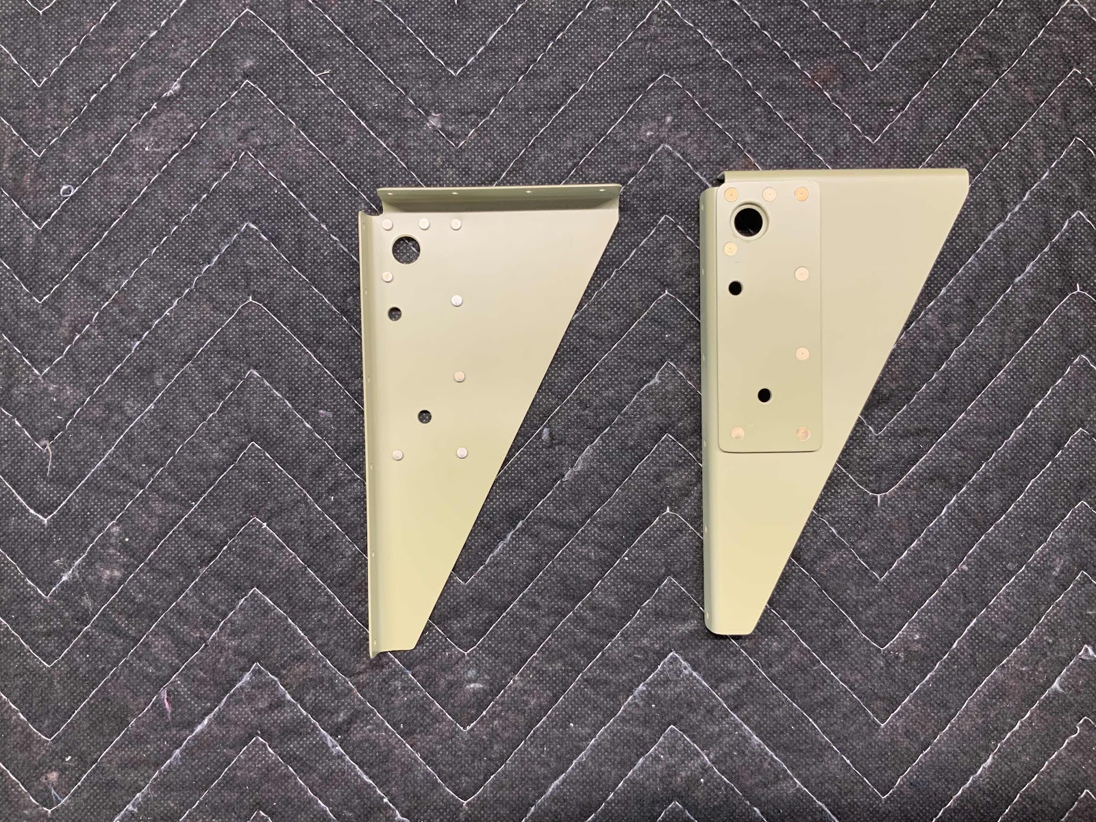
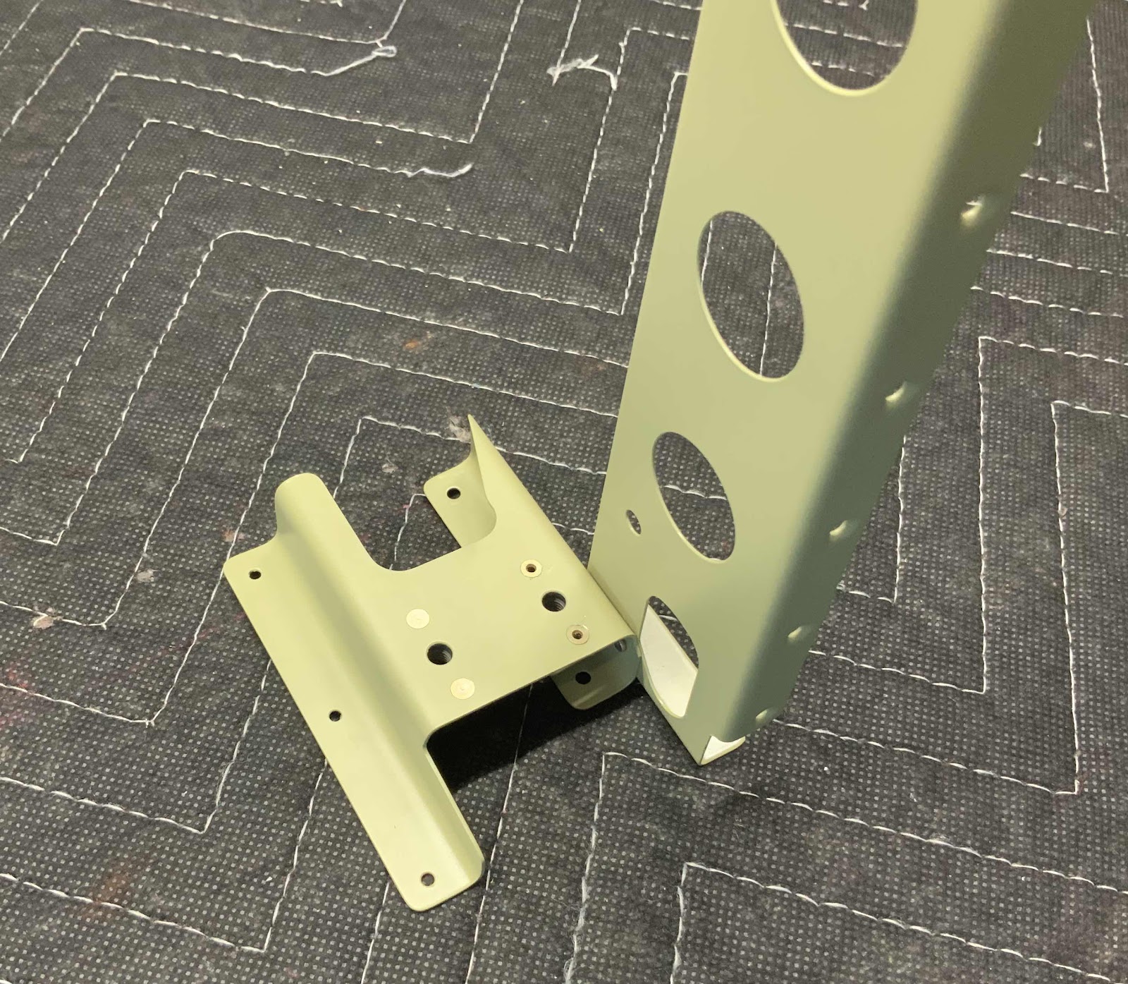
So far, all of the parts have been installed on the front or forward side of the Sub Panel.  Now, the F-01494-L & -R Instrument Panel Stand-Offs and the F-01477-L & -R Connector Brackets will get installed on the back or aft side of the Sub Panel.  Here is the left side.....


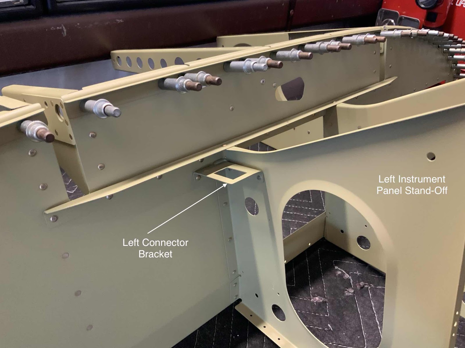
.....and the right side.


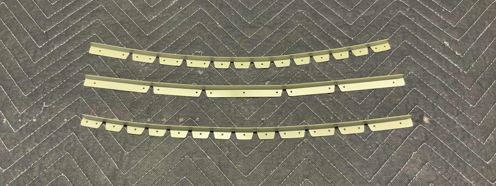
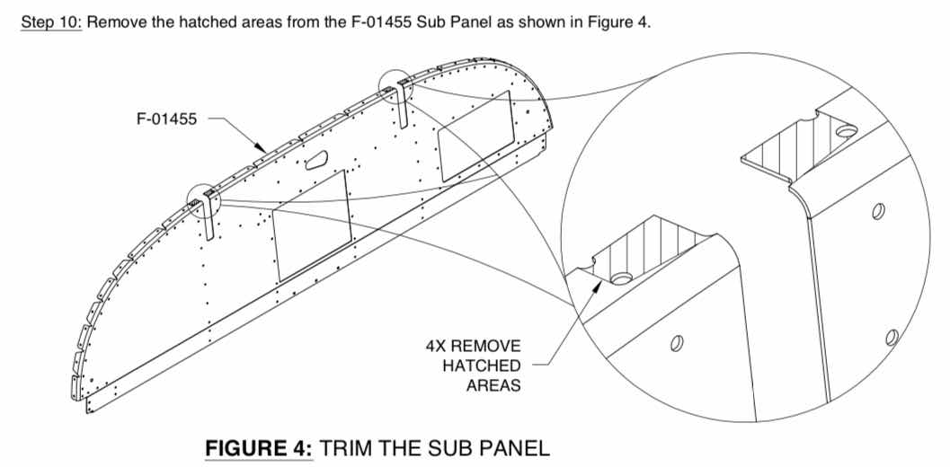
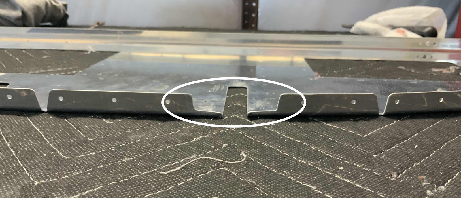
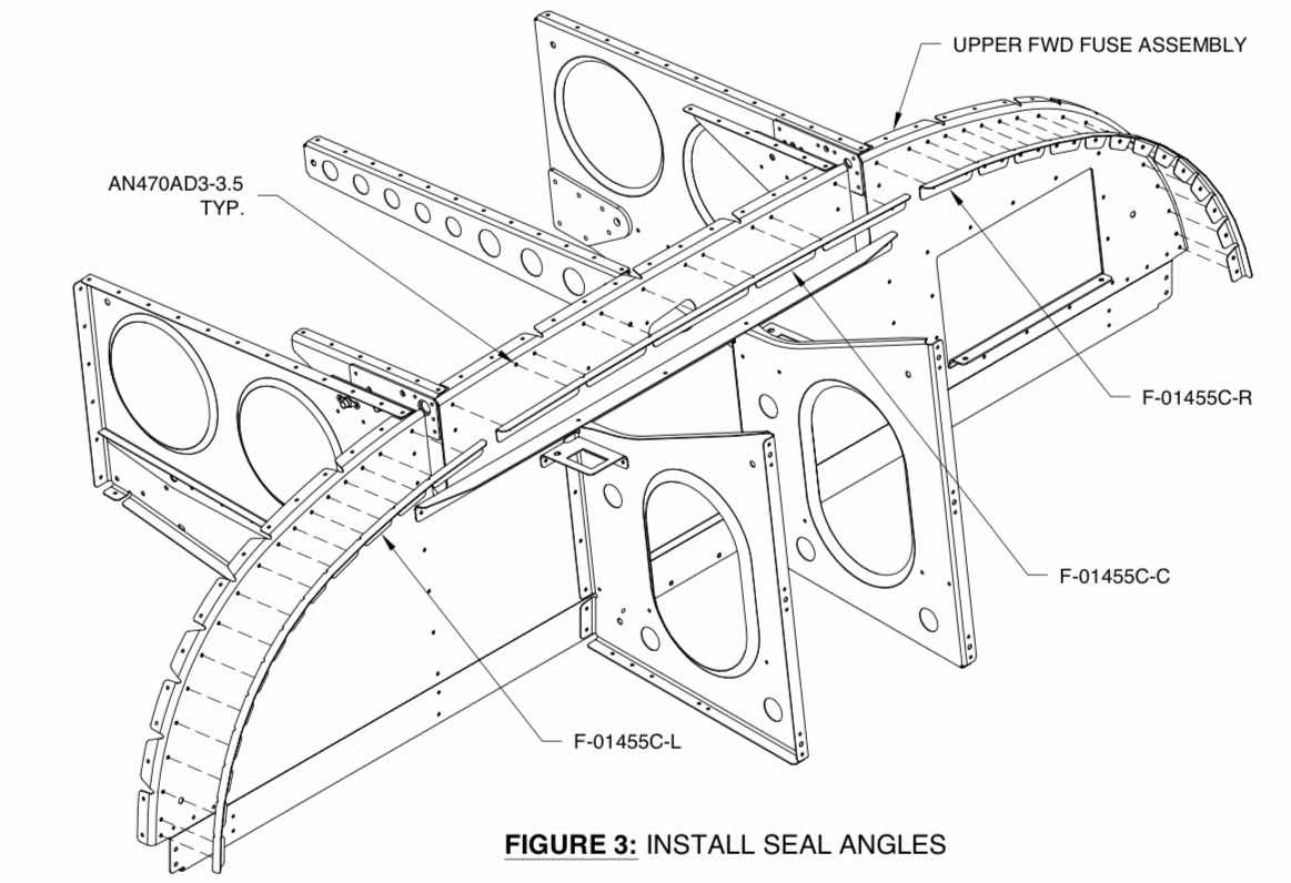
Lastly, for this session, the F-01455C-L & -C & -R Seal Angles were installed to the Sub Panel.  Here is what it looks like in the plans.....


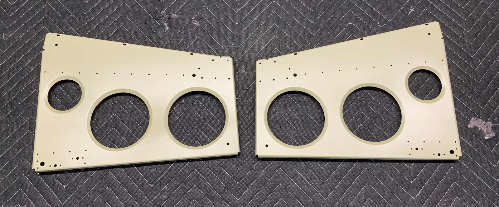
.....and on the plane.  Here is the Left Seal Angle.....

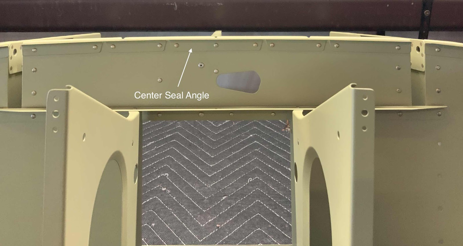
.....the Center Seal Angle.....

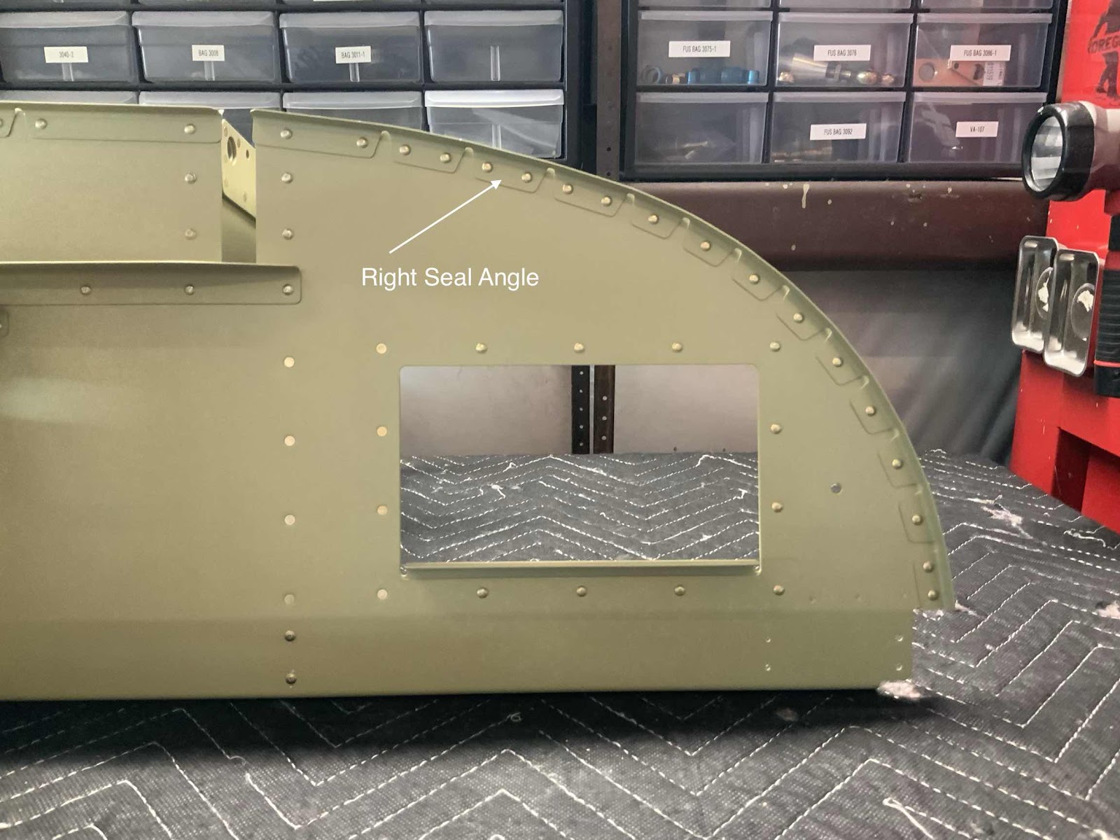
.....and the Right Seal Angle.

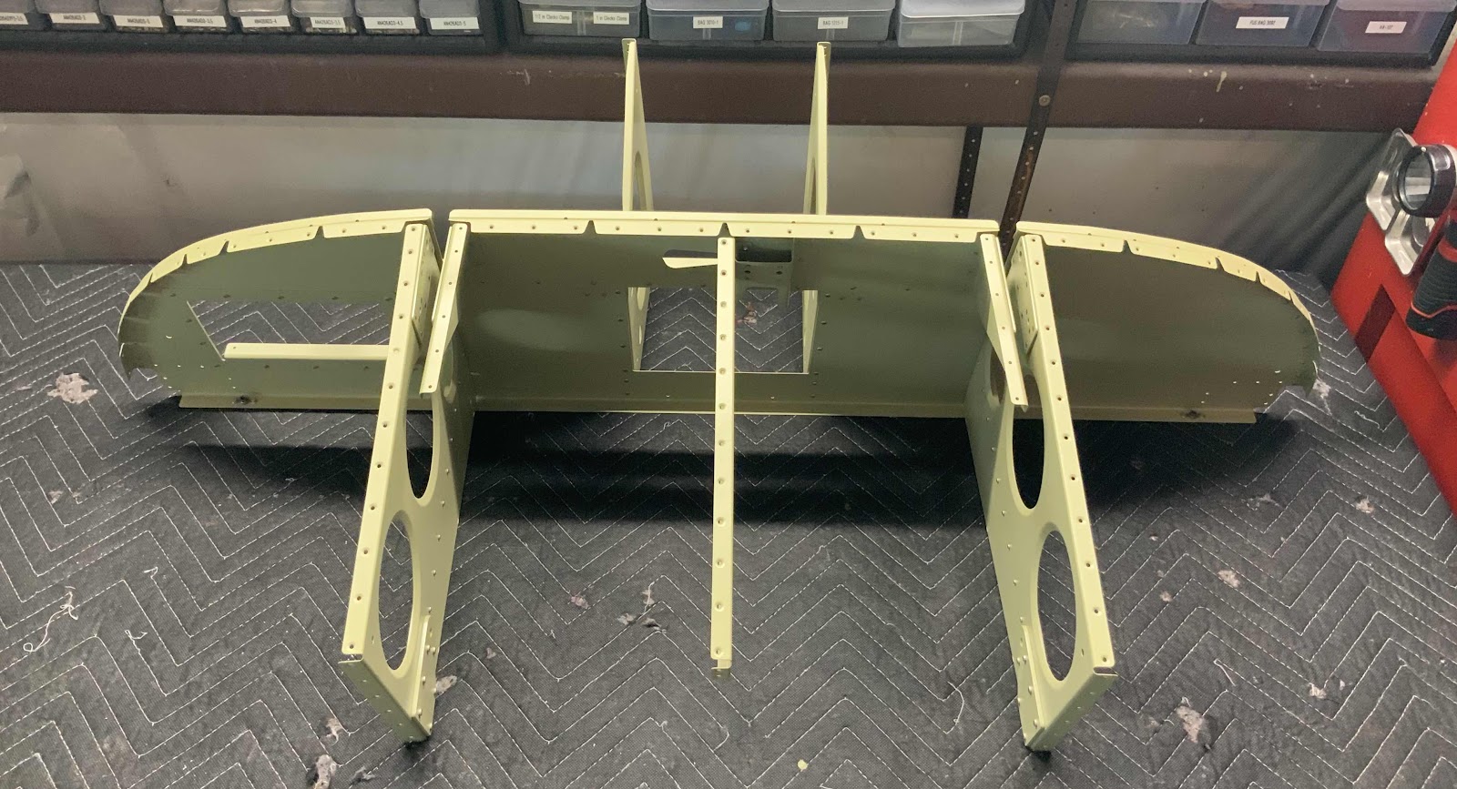
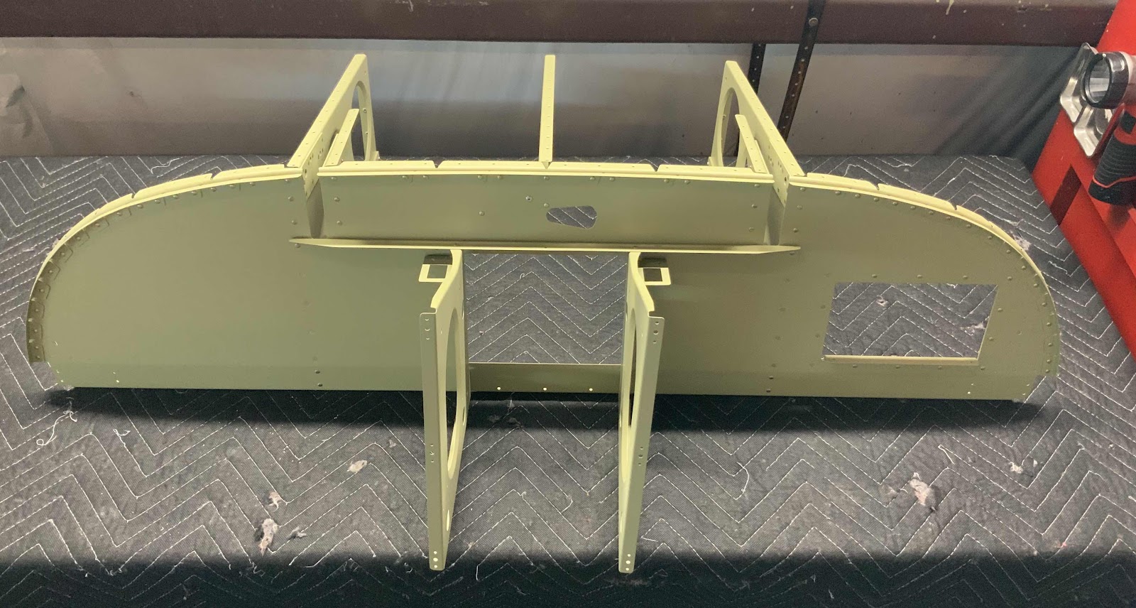
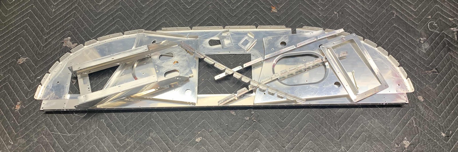
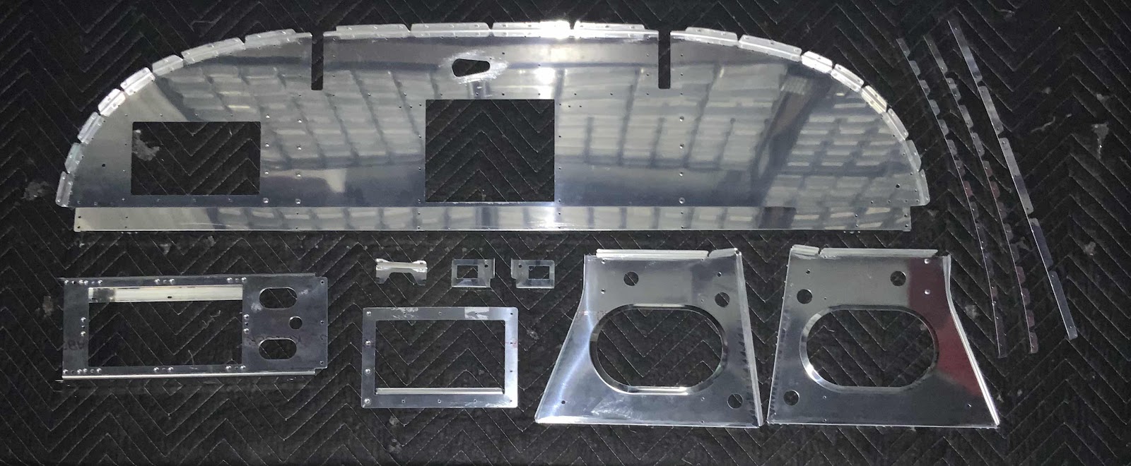
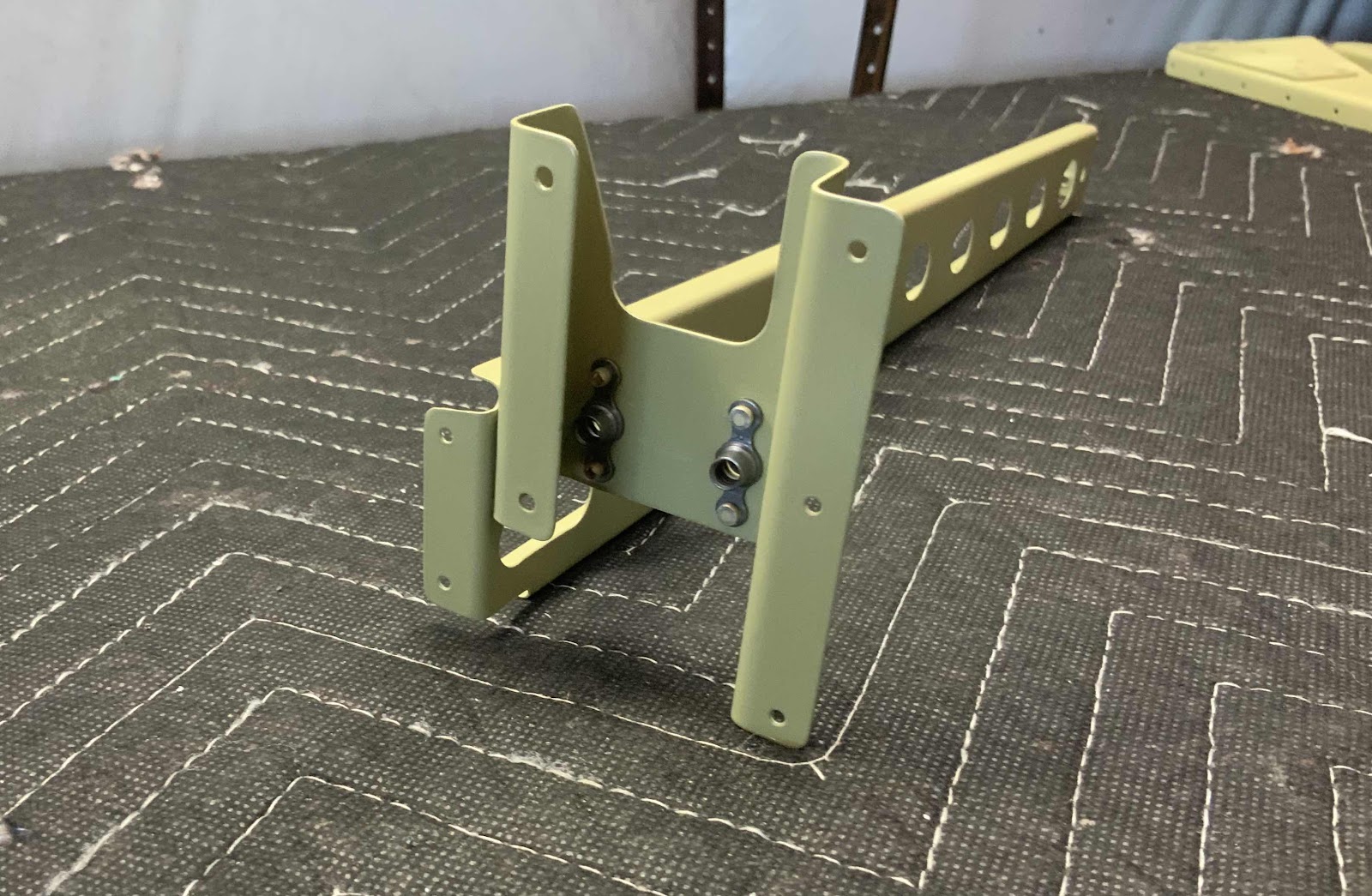
Here is a couple views of the “frame” that was assembled/riveted during today’s session.


Sunday, March 29, 2020

Fuselage, Upper FWD Fuselage (Parts 7, 8, 9)

I haven’t posted anything in the last few days (wasn’t much to show for Parts 7 & 8), but I have been working.  I will catch the blog up here with the three most recent work sessions.  
- - - - - - - - - - - - - - - - - - - - - - - - - - - - - - - - - - - - - - - - - - - - - - - - - - - - - - - - - - - - - - - - - - - - - - - - - - - - - - - - - -

Sunday, March 29, 2020 (Part 9)

In Part 8, all the parts and pieces were treated with Alumiprep and Alodine.  Today’s session was spraying them with Akzo primer. So, here goes.....

This is the F-01455 Sub Panel.....

.....F-14106 Wiring Channel.....

.....F-01494-L & -R Instrument Panel Stand-Offs.....

.....F-01455B Map Box Doubler.....

.....the F-01477-L & -R Connector Brackets and FF-00005 Cowl Pin Retention Bracket.....

.....and the F-01455-L & -C & -R Seal Angles.

There you have it.....that’s all the parts are now Akzo primed.  I will start the assembly process during the next session.
- - - - - - - - - - - - - - - - - - - - - - - - - - - - - - - - - - - - - - - - - - - - - - - - - - - - - - - - - - - - - - - - - - - - 

Saturday, March 28, 2020 (Part 8)

Not much to show, but I spent this session treating all the parts and pieces with Alumiprep and Alodine.  I will spray them with Akzo primer during the next session and identify each of the parts.
- - - - - - - - - - - - - - - - - - - - - - - - - - - - - - - - - - - - - - - - - - - - - - - - - - - - - - - - - - - - - - - - - - - - 

Friday, March 27, 2020 (Part 7)

I began cleaning the edges of all the parts shown in Part 6.....I finished doing that in today’s session.  Here is the pile of parts.....ready to be treated with Alumiprep and Alodine.

Thursday, March 26, 2020

Fuselage, Upper FWD Fuselage (Part 6)

During this session, I restarted the process of preparing the next “batch” of parts.  I looked through the plans to see what parts needed to be prepared and/or were riveted together next.  The parts shown below were those parts (at least over the next few pages of the plans).  To begin, I deburred all the holes on each piece and dimpled the appropriate holes according to the plans.


I also stared cleaning all the edges, but did not get finished.  I will finish the edge cleaning during the next session and all of them will be ready to be treated with Alumiprep, Alodine and Akzo primer.  I will identify each piece after they are primed in a future post.

However, I will talk about a portion of the prep work completed on the F-01455 Sub Panel.  The plans excerpt below shows two areas of material that needed to be removed.

Here is the finished product on the actual Sub Panel after I removed the excess material at each location.  I marked each area with a sharpie and used a hand nippler to remove most of the material.  Once that was done, I used a small fine hand file and 220 grit sandpaper to make the final adjustments on each side.


Tuesday, March 24, 2020

Fuselage, Upper FWD Fuselage (Part 5)

After letting the Akzo primer dry from Part 4, it’s now time to rivet some stuff together.  To start, the F-01456A-L & -R Rib Stiffeners (on the right) and F-01456B Gas Spring Brackets (on the left) were riveted to the F-01456-L & -R Fwd Fuselage Ribs.

Next, the two F-01462B Canopy Hinge Doublers were riveted to the F-01459-L & -R Canopy Hinge Ribs.


Two K1000-3 nutplates get riveted to the C-01436 Pivot Block Channel.  The nutplate on the left received two AN426AD3-3 rivets and the nutplate on the right got two CCR-264SS-3-2 rivets.

Now, the Pivot Block Channel gets riveted to the F-01493 Fwd Fuselage Channel using two AN426AD3-3.5 rivets.....but first, what had happened was.....

Confession #1:
Since I attached the picture above showing the two nutplates installed on Pivot Block Channel, I obviously did that BEFORE the Pivot Block Channel was riveted to the Fwd Fuselage Channel.....WRONG!  I should have attached the nutplates AFTER (as the plans instruct) because they get in the way of the yoke on the rivet squeezer (hand or pneumatic for me).  Soooooo, I tried several different way to accomplish this, but had to remove the nutplate in order to set the rivets.

Confession #2:
While removing one of the rivets between the Pivot Block Channel and the Fwd Fuselage Channel (while trying to make it work with the nutplate installed), the rivet tipped (because the nutplate prevented the sets from sitting square on the rivet) and had to be drilled out.  While drilling it out, the original #40 hole became elongated.....awesome!  So, I drilled that hole to a #30 and installed a AN470AD4-4 rivet.  Actually, turned out pretty well.

Here is the Pivot Block Channel and the Fwd Fuselage Channel FINALLY riveted together.

Another angle.....

.....and another.

Lastly, these are all the parts riveted together during this session.

Monday, March 23, 2020

Fuselage, Upper FWD Fuselage (Part 4)

In Part 3, I treated all the parts and pieces with Alumiprep and Alodine.  After letting the parts dry overnight, they were sprayed with Akzo primer.

These are the F-01456-L & -R Fwd Fuselage Ribs.....

.....the F-01456A-L & -R Rib Stiffeners and F-01493 Fwd Fuselage Channel.....

.....F-01459-L & -R Canopy Hinge Ribs.....

.....C-01436 Pivot Block Channel and two F-01456B Gas Spring Brackets.....

.....and two F-01462A (left) and F-01462B (right) Canopy Hinge Doublers. 

Sunday, March 22, 2020

Fuselage, Upper FWD Fuselage (Part 3)

Not much to show during today’s work session.  I countersunk the 11 #40 holes in the two F-01462A Canopy Hinge Doublers and the eight #40 holes in the two F-01462B Canopy Hinge Doublers.  Then, all the parts and pieces prepared in Parts #1 and #2 were treated with Alumiprep and Alodine.  I’ll let everything dry overnight and spray them with Akzo Primer during tomorrow’s session.

Saturday, March 21, 2020

Fuselage, Upper FWD Fuselage (Part 2)

Here are the parts that will get prepared during today’s session.  

1.  F-01493 FWD Fuselage Channel (the part at the top)
2.  F-01459-L & -R Canopy Hinge Ribs (had to be separated)
3.  C-01436 Pivot Block Channel
4.  F-01462A Canopy Hinge Doubler (x2)
5.  F-01462B Canopy Hinge Doubler (x2)

Done!  All of the prep work has been completed on the parts listed above.  All parts were separated (if needed), had the edges cleaning, holes deburring and dimpled (if required).  All of the parts are now ready to be treated with Alumiprep, Alodine and Akzo primer. 

In the picture below, I also include the parts that were prepared during he last session.

Fuselage, Flap Actuation System (Part 2)

During the last session, I installed the two Flap Torque Arms and Flap Crank.  Today, I will prepare and install the ES 85615-10 Linear Actuator (Flap Motor).  The first step is to drill an angled “1/16” hole through the upper lip of the extension shaft and should exit outside the profile of the jam-nut, but within its outside diameter”.  All of those words look like this in the plans.....

So, here is my 1/16” hole drilled through the extension shaft as described above.  Now, the plans also contain the following NOTE:

“Avoid removal of the ES 85615-10 Linear Actuator jam-nut and rod end since the length of the assembly has been set at the factory”.

In the picture below, I kinda didn’t do that....well sorta!  I initially tried to drill the hole with the jam-nut undisturbed.  However, the drill bit would have drilled partially into the jam-nut (my angle was off ever so slightly).  So, I unscrewed the jam-nut, finished drilling the hole and returned the jam-nut to it’s position from Van’s.

Then, inserted the .025 safety wire into the hole that was just drilled.

While working with the Flap Motor, I saw “Van’s” engraved on the back.  Thought it was pretty cool.

The top of the Flap Motor is secured to the F-01446-L & -R Motor Brackets with an AN4-12 bolt and hardware.  Per the plans, wheel bearing grease was applied to the bolt.

The bottom of the Flap Motor (Extension Shaft) is secured to the WD-1023A Flap Crank with an AN3-12A and hardware.  Additionally, safety wire is routed through the hole drilled in the extension shaft and around the .259X.375X.168 Bushing.

Here is the installed Flap Motor.....BOOM!


Section Complete

I ended up removing the Van's flap actuator and installing a different one.  Please see 
Modifications & Upgrades for the installation of the PH Aviation Services RV Max Flap Actuator.