This blog was created to memorialize the building process of my Van's Aircraft RV-14 and to satisfy the requirements for certification in the Experimental Amateur Built Aircraft category. It will also serve as a central location for ME to reference in the future on processes and techniques I used during the build. Additionally, it will allow my family, friends, and other interested builders the opportunity to follow along during my build…..and might be helpful to someone along the way.
The Elevator is COMPLETE! During tonight's session, I only had to install the counterweights and Trim Tab Servo. Here is the Trim Tab Servo installed on the Left Elevator Bottom Skin with the seven screws.
These pictures show the counterweights attached to the Right Elevator.
I started tonight's session by riveting the Right Elevator Trailing Edge. The AN426AD3-4.5 rivets were double flush riveted using the Safety Pin Squeezing Tool. The picture below doesn't do the results justice, but this is the flush shop head side.
After those 51 rivets were installed, I moved on to rolling the Leading Edges. My buddy Jeff helped me with the Leading Edges and we followed the directions provided in the plans. We used a 1 1/4" wooden dowel that I purchased at Lowe's to make the roll. The size of the dowel seemed to work out perfectly. Here are a few pictures of the Left Elevator after being rolled and having the AD-41-ABS rivets installed.
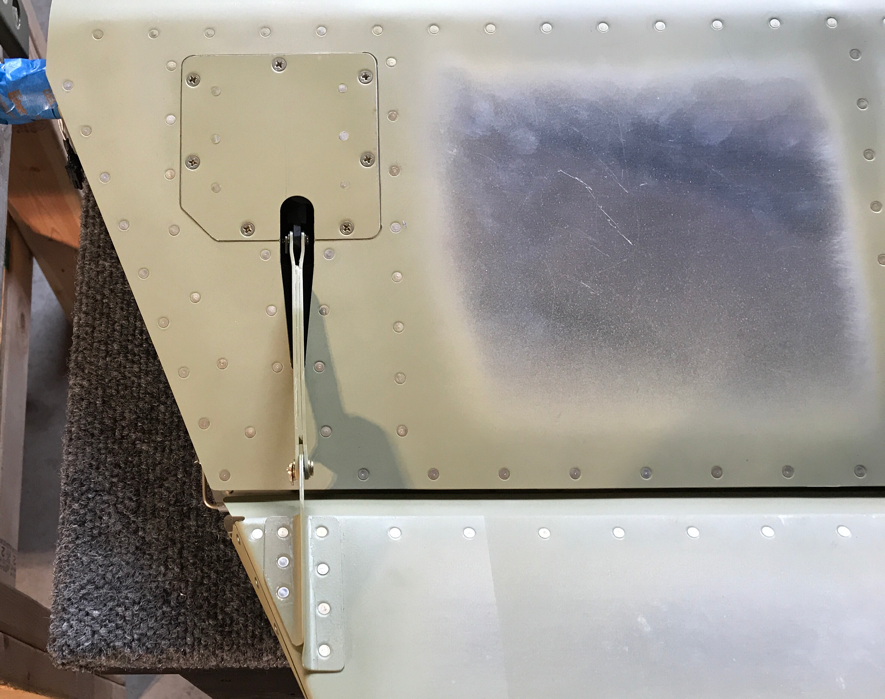
In this picture, you can see the opening for the Trim Tab Servo connection.
And here are a couple of pictures of the Right Elevator after having the rivets installed.
I'm just about two session away from wrapping up the assembly of the Elvator(s), so I worked a short session this evening. I removed the board/weights that weighted the Skins down on the Ribs to help the tank sealant cure. The tank sealant appears to have cured properly, so I installed the last rivets on the Right Root Rib and Tip Rib.
This is the final six rivets (three on each side) on the Right Root Rib.....
And the final six rivets (three on each side) on the Tip Rib.
Tomorrow, I will start by installing the double flush rivets on the Trailing Edge. Finally, the Leading Edges on the left and right sides will be rolled and riveted. Then, that will complete the Elevators.
The last step to completing the Elevators is to trim and install the Counterweights. Since I'm weighting for the Proseal to cure in the Right Elevator, I decided to go ahead and prepare the counterweights. Here are the four E-614 Counterweights.....
And here is what the plans tell me to do to them.....
I started by Final-Drilling #12 the two holes in each of the counterweights and then trimming them accourding to the instructions above. Here they are after all the trimming is completed.
The two inside counterweights also required a little more modification. The excerpt below instructs the material to be removed in the hatched areas.
Here is one of the inside Counterweights after the excess material was removed.
Now, all I have to do is install the Counterweights on the Elevators with the proper hardware. One last task remaining to complete the Left Elevator is to make the Micro Molex connector. The five pins shown below in the excerpt had to be crimped to the appropriate wires from the Trim Servo.
Here are the five pins installed on the five wires from the Trim Servo.....
As I mentioned in yesterday's post, I attached the Front Spar to Ribs. Today, the Top and Bottom Skins were riveted to the Front Spar with AN426AD3-3.5 flush rivets. You can see the shop head side of the rivets on the Front Spar flanges circled below.
Here you can see the 3M Adhesive Tape on the Trailing Edge Wedge. It will be set in place after the Foam Ribs are installed.
I mixed up some Proseal Tank Sealant to install the Foam Ribs. Here you can see one of the Foam Ribs installed between the Skins. There is a 1/32 inch (approximately) layer of Proseal on the inside of the Top and Bottom Skins and Rear Spar.
After all six of the Foam Ribs were installed, a weighted board was placed on top to hold everything tight to allow the Proseal to cure. Now, I'll let the Proseal cure for a few days before I continue working. As mentioned earlier, the Trailing Edge Wedge was also installed between the Skins and is being held in place with clecos. The only two things left to do is roll the leading edges and attached the counterweights.
I decided (well, decided for me really) to build the Elevators separately and NOT together. The original WD-605-R-1 Elevator Horn (for the Right Elevator) I received with the kit had several spots where the powder coating was coming off. I spoke with Gus and he recommended two courses of action:
1. Return it for another one
2. Use a wire brush to remove the flacking powder coating and then prime it
I decided to send it back and get another one. So, that's how the decision to assemble the Elevators individually was made for me. So, I started with the Left Elevator while I waited on the Right Elevator Horn. The Left Elevator is mostly complete (little work left on the Trim Servo wiring), so I started to work on the Right side.
I scuffed and primed the new Elevator Horn and attached it to the Right Front Spar and Right Rib Root with 12 AN470AD4-4 universal head rivets. The picture below shows the six rivets attaching the Elevator Horn to the Right Front Spar.
This view shows the six rivets attaching the Elevator Horn to the Right Root Rib. Additionally, on the left side of the picture, you can see the two universal head rivets attaching the Right Root Rib to the internal Gusset (which is a riveted to the Right Rear Spar).
Once the Elevator Horn was attached, the Front Spar was inserted between the Upper and Lower Skins. The Spar was then clecoed to the Ribs. Like a good student, I learned from my previous mistake.....I made sure the Elevator Skin was ON TOP OF the Counterbalance Skin. (See Empennage, Elevator (Part 21) for additional explanation).
I then attached the Front Spar to the Ribs using LP4-3 pop rivets. The picture below shows a section of the Front Spar attached to two of the Ribs with the three silver vertical rivets.
Alright, I let the tank sealant cure and bond to the Ribs for a couple of days, so I shifted work back to the Elevator. The photo below shows the Top Left Elevator Skin after the having the Trailing Edge double flush riveted. The rivets circled are the manufactured heads of the AN426AD3-4.5.....
And this is the "double flush" shop head on the Bottom Left Elevator Skin. I used the same Safety Pin Squeezing Tool (purchased from Cleaveland Aircraft Tool) to set the rivets. I will also use the tool for the Trailing Edge of the right side Elevator. This tool produces perfect rivets on the Trailing Edge.
Pictured below is the Hinge Pin that will be inserted into the Piano Hinge to attach the Elevator Trim Tab to the Left Elevator Trailing Edge. The Hinge Pin came in one long rod about 36" and it had to be bent as shown below. I used a padded vice to hold the pin and gently tapped the pin with a rubber mallet to form the angles.
Here is the pin inserted into the Piano Hinge. You can also see the 1/16th hole I drilled in the Rear Spar. This hole is used to hold the Hinge Pin to the Rear Spar with safety wire. The safety wire will prevent the Hinge Pin from vibrating out.
Here is the Trim Tab attached to the Left Elevator Skin.....hopefully for the last time.
I started today'session by separating the F-01486D, E, and F J-Stiffeners. The Stiffeners came in one long piece and had to be separated into three individual pieces as shown below.
The F-1037A, B, and C Battery Angles were separated into four individual parts. Here is what they look like after preparation. F-1037B need an additional step to complete its preparation. I had to drill a #30 hole through the middle of the bend radius and then remove the area of aluminum. The area removed is circle in the second picture below.
The F-01486A-L & -R and the F-01486B-L & -R J-Stiffeners (4 total pieces) need some excess aluminum removed. The area circled below was removed from all four J-Stiffeners.
Two tabs on each of the Aft Fuselage Longerons were removed and the F-01410B-L & -R Bulkhead Doublers were separated. There is anything to show for the Aft Longerons, but below are the Bulkhead Doublers (along with the previously prepared F-01473A Stiffener Angles).
The two F-01497B Cable Guides came in two strips as indicated in the first picture. They had to be prepared according to the plans excerpt below and provided eight individual pieces. The finished product is in the second picture.
The next piece to get prepared was the F-01473A Stiffner Angles. The material was removed where the triangle is in the first picture below. The second pictures shows the completed angles.
I had previously complete the step shown below in the plans excerpt. However, I was not very pleased with the results. So, I ordered two new Trailing Edge Wedges from Van's and produced a MUCH better result on the second attempt. The second picture below (kind of hard to see) has the excess material removed as indicated by the plans. The third shows the Trailed Edge Wedge installed between the Skins being held on with clecos.
The same process used to install the Foam Ribs in the Trim Tab were also used to install the Foam Ribs in the left side of the Elevator. The board and bucking bars are weighing down the Skins to ensure a good bond between the Ribs and the Skins. I used tank sealant as described in the plans.
I also temporarily attached the Trim Tab to the rear of the Left Elevator.