Showing posts with label Section 20-Bottom Wing Skins. Show all posts

Monday, December 3, 2018

Wings, Bottom Wing Skins (Part 16)

In Part 15, I completed riveting the Bottom Inboard and Outboard Wings Skins on the Right Wing.  Now, I’m moving on to the Left Wing.  As with the previous post, this will also be an all encompassing post for the 12 works sessions it took to complete riveting the Bottom Skins on the Left Wing.


Friday, November 16th:  66 Rivets
When I was counersinking the Fuel Tank Attach screw holes in Section 13, I accidentally let one of the holes get bigger than it was supposed to be.  So, after lots of colorful adjectives, I decided to take a deep breath and fix it LATER.  Well, LATER is now.  The countersunk hole essentially provides a “cavity”, if you will, for the corresponding dimpled Tank Skin to sit in when it is screwed into place.  Because the hole is presently too big, when the screw is installed it would “pull” the Tank Skin into the cavity and deform the Tank Skin.....can’t be having that!  Since I removed to much material (aluminum), I have to ADD some material.  After consulting several A&P’s and previous RV builders, I decided to use Hysol as a filler.  Hysol is used as a structural glue on many different certified aircraft models.  So, I figured it was the best fix for my “problem”.

First, I drilled out the two rivets that held on the nutplate (as shown below) and put a piece of metal tape on the underside of the Spar Flange under the hole in question.  Once the Hysol was properly mixed and cured, I filled the hole and let it dry.  After the Hysol was dry, I sanded the area with 220 grit sandpaper to smooth out the Hysol to the Spar Flange.  Lastly, I sprayed on some new primer to make it look “pretty”.  NOTE:  the primer is NOT on the Flange in the picture below.....its not pretty!

Next, I used clecos to hold the nutplate in position on the OUTSIDE of the Main Spar Flange.  I then used the nutplate as a guide to drive the screw hole through the Hysol.  Lastly, I used a hand deburring tool to make the appropriate countersink in the Hysol for the dimpled Tank Skin.  To hold the nutplate in place to re-install the rivets, I partially installed one of the Tank Attach screws as shown below.  Once the nutplate was back into place, the “repair” was acceptable.....build on!!!

Here are the first rivets that were installed on the Inboard Bottom Wing Skin.


Saturday, November 17th:  8 Rivets

Wednesday, November 21st:  89 Rivets


Friday, November 23rd:  74 Rivets


Saturday, November 24th:  45 Rivets
I’m not really sure why I did this, but I decided it would be a good idea to rivet the angle bracket for the Pitot Tube base plate on the Wing Rib.....shouldn’t have done that.  The lip of the base plate goes UNDER the Main Spar Flange and OVER the angle bracket.  Let’s just say....IT DON’T WORK when trying the rivet the on the Wing Skin.

This is the opposite angle of the Pitot Tube Mount from the picture above.

The inboard edge.....

.....and the outboard edge.  You can see the two manufactured heads of the rivets used to attach the Angle Bracket to the Wing Rib.....

.....and the associated shop heads.  I eventually had to drill out these rivets and remove the Angle Bracket.  This allowed the Pitot Tube Mast to be easily installed through the Access Panel.  The Angle Bracket will be installed within the next few work sessions after the Skin in riveted on the Wing.


Sunday, November 25th:  32 Rivets

Wednesday, November 28th:  33 Rivets

Friday, November 30th:  91 Rivets


Saturday, December 1st:  100 Rivets

Sunday, December 2nd:  146 Rivets
Now that all the rivets have been set for the Bottom Wing Skins, it’s time to install the Pitot Tube Mast.  It’s a whole lot easier now since I removed the Angle Bracket....which will be riveted to the Pitot Tube Mast base plate and Bottom Skin where the orange tape is located.  Since this is a “custom” install, I had to insert several different AN426AD3 rivets to get the proper length rivet because of the thickness of the Pitot Mast base plate.

The Skins are now riveted to the Pitot Tube Mast base plate.

Another view of the Pitot Tube Mast.


Monday, December 3rd:  3 Rivets
Lastly, the Angle Bracket was re-installed to the Wing Rib and Pitot Tube Mount base plate as shown in the picture below.  I decided to make a modification to the Angle Bracket.  Originally, the Angle Bracket that attaches to the base plate touched the welding bead around the base plate and Pitot Tube Mast.  I didn’t like this, so I trimmed the Angle Bracket away from the welding bead.  I also considered doing the same thing where the Angle Bracket gets riveted to the Wing Rib.  You can see a slight “gap” between the Angle Bracket and Wing Rib lightening hole in the picture below.  In order to trim this part of the Angle Bracket flush with the web of the Wing Rib (and lightening hole), it would be to close to the rivet for the proper edge distance.  I decided to leave it the way it was.  Like I said in a previous post, the Dynon Pitot Tube Mast is not designed for the RV-14, so I had to make a few modifications.....such as in Parts 11 and 12.

The completed installation of the Pitot Tube Mast.


Section Complete

Thursday, November 15, 2018

Wings, Bottom Wing Skins (Part 15)

With all the nutplates installed during the previous session, it’s now time to install/ rivet the Bottom Inboard and Outboard Wing Skins for the Left and Right Wings.  To start, I have decided to start with the Right Wing.  According to the plans, there are 675 rivets that need to be installed to complete the Bottom Skins installation.  Since there are so many rivets to install, I decided not to publish a post every day regarding how many rivets that were set.  Instead, I kept track of all the rivets installed, when, and the length of the session.  I use this blog entry to encompass all the work sessions associate with the installation of the Bottom Wing Skins on the Right Wing.  I will use the same “format” for completing the Left Wing.

Friday, November 2nd:  53 Rivets


Saturday, November 3rd:  94 Rivets

Sunday, November 4th:  69 Rivets

Monday, November 5th:  55 Rivets


Wednesday, November 7th:  8 Rivets


Thursday, November 8th:  7 Rivets

Friday, November 9th:  86 Rivets

Sunday, November 11th:  132 Rivets


Tuesday, November 13th:  52 Rivets


Wednesday, November 14th:  74 Rivets


Thursday, November 15th:  45 Rivets

Thursday, October 11, 2018

Wings, Bottom Wing Skins (Part 14)

During today’s session, I installed the remaining 32 K1100-08D nutplates on the Right Wing Outboard Bottom Skin and the Left Wing Inboard and Outboard Bottom Skins.  These nutplates will be used for the screws that will attach the six Wing Access Plates to the bottom of the Wings.

This is the outside of the Left Bottom Inboard Wing Skin showing the manufactured heads of the rivets attaching the eight nutplates.....

.....and on the inside.  AN426AD3-3.5 rivets were used to attach all 48 nutplates.

This is the outside of the Left Bottom Outboard Wing Skin with 16 nutplates attached.  In this picture, you can also see the “hole” that was cut in the Skin for the Pitot Tube Mast, along with the associated mounting/rivet holes.

Here is the nutplates attached on the inside and the opposite side of the Pitot Tube Mast “hole”.

Here is the outside of the Right Bottom Inboard Wing Skin showing the manufactured heads of the rivets attaching the eight nutplates.....

.....and on the inside.

Lastly, pictured below is the outside of the Right Bottom Outboard Wing Skin with 16 nutplates attached.....

.....and on the inside.


Tuesday, October 9, 2018

Wings, Bottom Wing Skins (Part 13)

After all the prep work was completed, it was time to Alumiprep, Alodine, and Akzo prime.  Below shows the seven parts that will make up the ADAHRS or GMU22 Magnetometer Mounting Bracket.

Here are the same seven pieces clecoed together.  This is the “top” view.....

.....and this is the “bottom” view.


After each of the pieces were treated with Alumiprep and Alodine, they were hung up to dry prior to getting primed.  The picture below shows the seven pieces that make up the ADAHRS or GMU 22 Magnetometer Mounting Bracket and the six Access Panels 
(3 for each Wing) used on the Left and Right Bottom Skins.

Here are the seven pieces of the ADAHRS or GMU 22 Mounting Bracket after getting primed.

Shown below is the “top” view of the ADAHRS or GMU 22 Magnetometer Mounting Brackets completely riveted together.  Additionally, the Mounting Bracket has been riveted to the J-Stiffener.  (Not sure why the color difference between the pictures above and below.  I think the one on the bottom was taken at night with the flash on my phone).

Here is the “bottom” (opposite side of the picture above) of the ADAHRS GMU 22 Magnetometer Mounting Bracket.

Here are the Left and Right Inboard and Outboard Bottom Skins and J-Stiffeners after being treated with Alumiprep and Alodine.  The next step for them is to be Akzo primed.  I’m not going to show an “after primer” picture of the Skins.  You will get to see “finished” pictures when the nutplates are installed in the Part 14.

After the Akzo primer was dry, I started installing the 48 K1100-08D nutplates on the Inboard and Outboard Bottom Wing Skins of each Wing.  I began by installing the 16 nutplates on the Left Outboard Wing Skin (completed pictures will be shown in the next post when all four Bottom Skins are finished).  During the next session, I will install the remaining 32 nutplates.


Thursday, October 4, 2018

Wings, Bottom Wing Skins (Part 12)

In the previous post, I showed the Pitot Mast with a mark on it indicating it’s center point.  To get that center point, I measured the width of the “base plate” at 2.994 inches.....

.....and took half (1.497 inches).

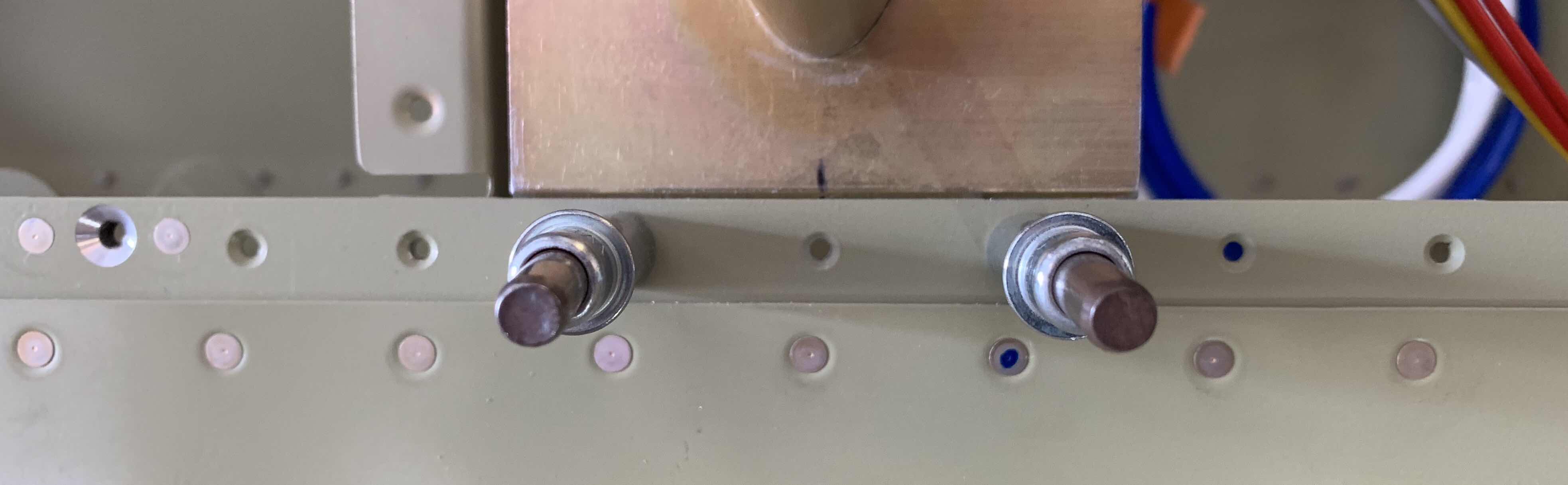
Since I am only able to use three holes on the RV-14 to attach the base plate to the Main Spar, I lined up the mark with the center hole to be used for the installation.  Once the center of the base plate was lined up, I clamped/clecoed it into place, match-drilled the center hole, installed a cleco, and repeated the process for the two outside holes.

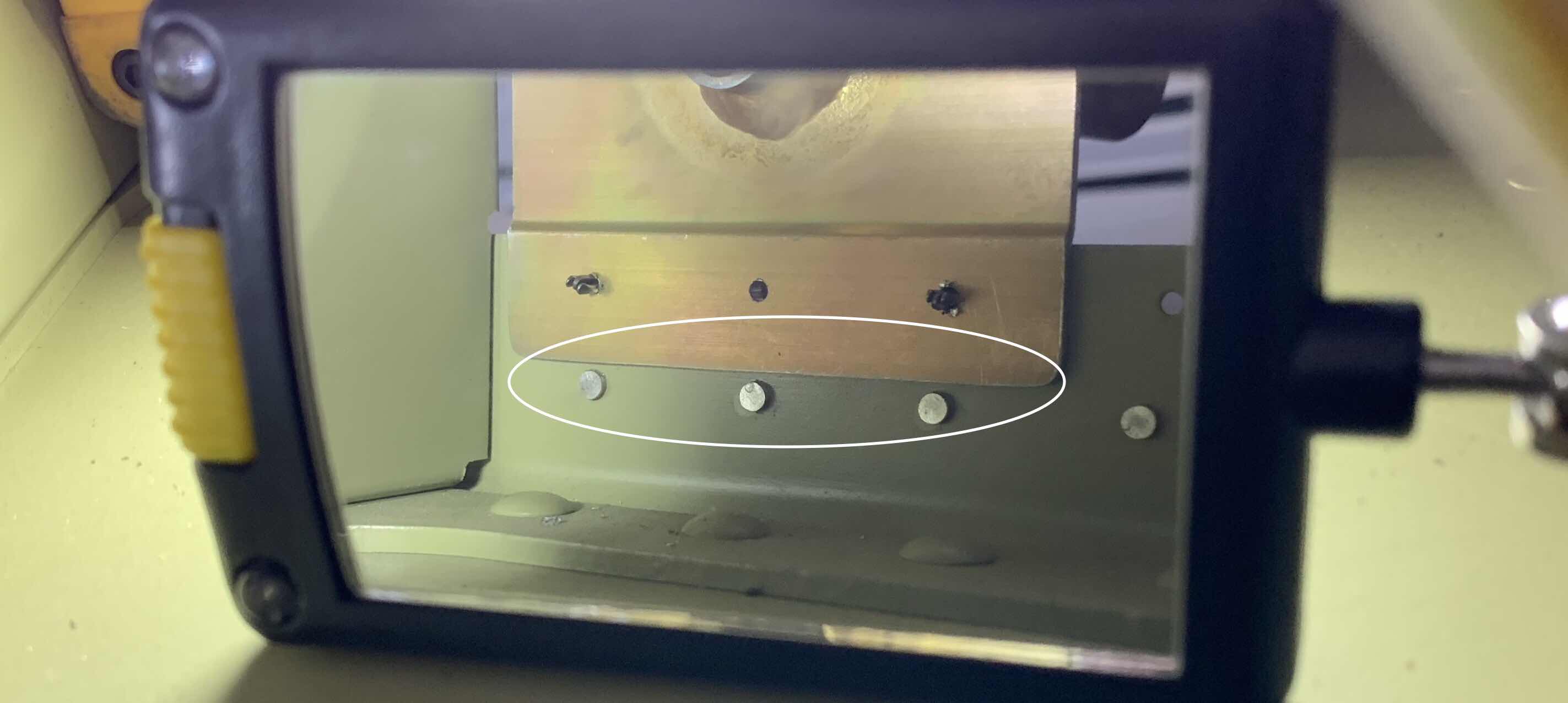
Here, I used an inspection mirror to show the back side of the base plate against the Spar.  From this angle, you can see a couple of things.  First, the three holes that were match-drilled from the Spar through the base plate (the two outside holes have clecos installed).  Second, the gap I created between the bottom of the base plate and three rivets below it (circled in white).  This area had to be trimmed and filed because the base plate “sat” on top of the rivets and caused the plate to be to far aft.   So, I used a combination of Scotchbrite Wheel, hand file, and 220 grit sand paper to complete the appropriate trimming of the base plate.

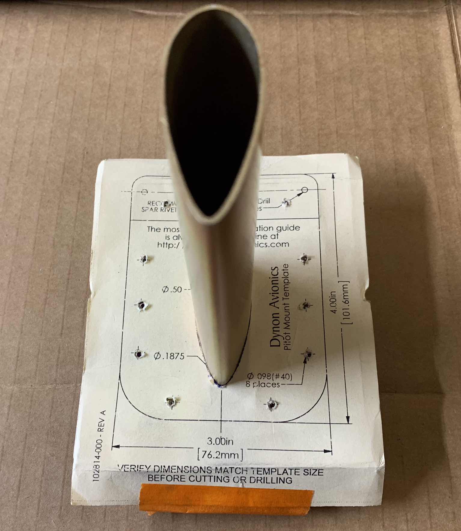
I decided I wasn’t the biggest fan of the paper template (it was a very good template, just flimsy) supplied by Dynon, so I used the their paper template to create an aluminum one from some scrap.  First, I used a razor blade to remove the center portion of the paper template to fit around the Pitot Mast.  Then, I marked the three holes I previously match-drilled with the Spar on the paper template, as shown below.

Next, I taped the paper template onto the aluminum, traced the center mast cutout, and drilled the three “Spar” holes and eight Skin holes through the aluminum.  Finally, I removed the center mask cutout (more on that below).

Lastly, I placed the aluminum template on the Pitot Tube mast and clecoed them together using the three Spar holes.  Then, I used a sharpie to mark the eight holes from the template to the base plate.  All three pieces are shown below, including the marked hole locations on the base plate.

I took the “new” aluminum template and clecoed it to the Bottom Skin at the three Spar holes.  Once in place, I traced the center Pitot Mast cutout onto the Bottom Skin and used these two unibits to remove a majority of the material.

Next, I used my angle grinder with a grinding bit to trim up to the traced edge.

And finally used a combination of a fine hand file and 220 grit sandpaper to make the final shape.  I had to put the Pitot Mask in and out several times to get the final fit I wanted with the Skin.

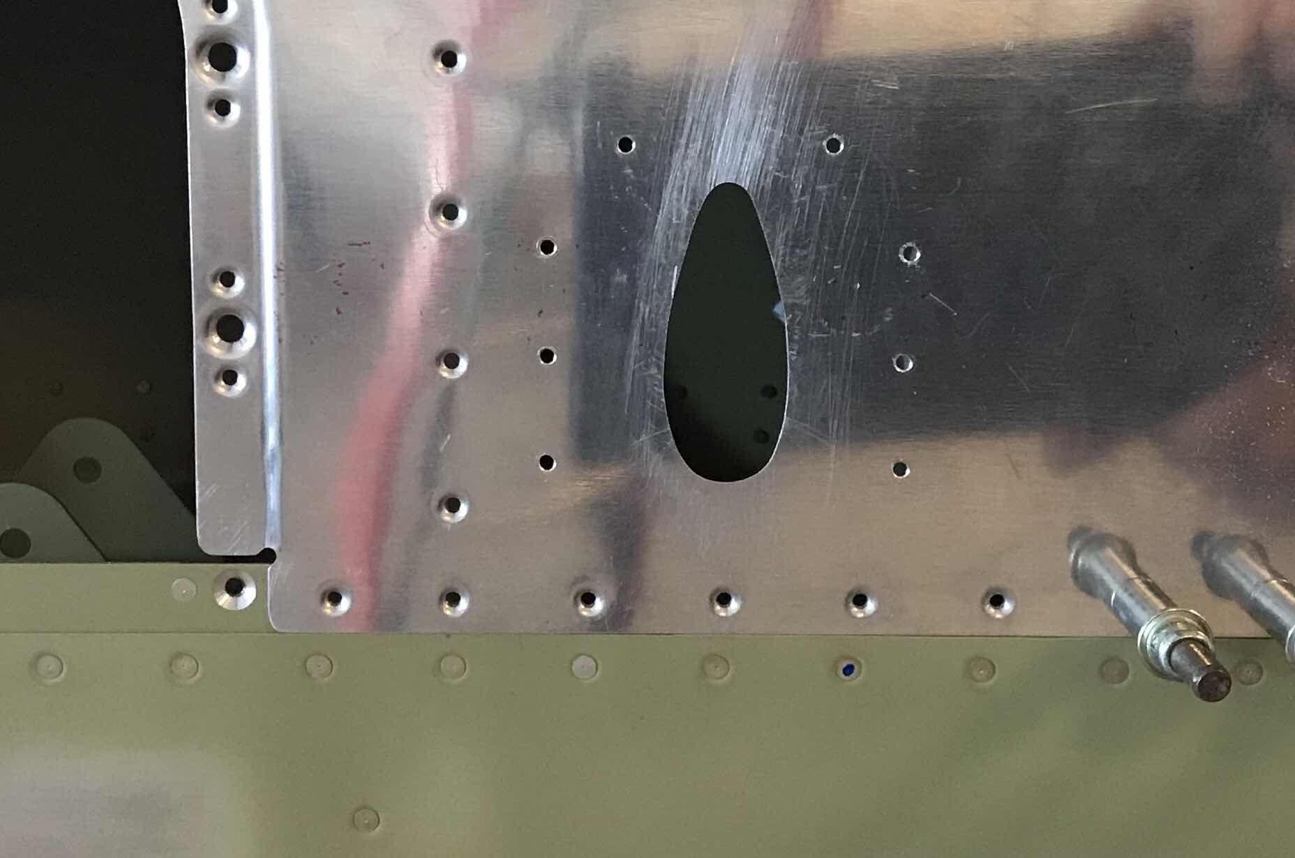
Now, I needed to match-drill the Skin attach holes.  I inserted the Pitot Mast through the Bottom Skin, placed the template over the Mast, and clecoed them together with the three Spar holes.  Lastly, the remaining eight Skin holes were match-drilled.


Here are the eight Skin attach holes after removing the template.....

.....and the holes in he Pitot Mast base plate.

The final step on the Bottom Skin was to dimple the attach holes......

.....and the final step on the base plate was to countersink the Skin attach holes to accept the dimpled holes in the Skin above.  (The three Main Spar attach holes do not get countersunk because they sit flat on the Main Spar).