This blog was created to memorialize the building process of my Van's Aircraft RV-14 and to satisfy the requirements for certification in the Experimental Amateur Built Aircraft category. It will also serve as a central location for ME to reference in the future on processes and techniques I used during the build. Additionally, it will allow my family, friends, and other interested builders the opportunity to follow along during my build…..and might be helpful to someone along the way.
While waiting on some riveting help, I decided to move on to the next section and start preparing some parts. As the section is titled, Aft Fuselage Attachment, there are only be a few parts that need to be prepared....the focus of the section is connecting the two “halves” of the Fuselage together.
The first two pieces to be prepared are the F-01406A-L & -R Bulkheads. The picture below shows the two completed parts. Each part had the holes deburred, edges cleaned, appropriate #40 and #30 holes dimpled, treated with Alumiprep, treated with Alodine and Akzo primed. The next step is to install the required nutplates.
The next part to get prepared is the F-01406C Bulkhead (top piece). This part was prepared in the same manner as the two Bulkheads above. Additionally, the two F-1231D Roll Bar Bases (to be used in Section 29) were treated with Alumiprep, Alodine and Akzo Primer.
Started today’s session by screwing the F-14144 Seatback Gussetts to the F-01405F Brace. There are a total of four Seatback Gussetts that get installed on the Brace. Pictured below are the the two “inside” Seatback Gussetts. Each of the four Seatback Gussetts are attached to the Brace using two MS35214-31 screws, two NAS1149FN632P washers and two AN365-632A Nylok nuts.
Next, the four F-01405N Seat Back Adjustment Guides previously fabricated are attached to the Brace. Each of the four Seat Back Guides were aligned with the forward edge of the F-01405K Guides (even with the top edge of Seat Back Guides in the picture below) and matched-drilled #30. The #30 holes matched-drilled in the Seat Back Guides were then countersunk to accept the heads the rivets attaching them to Brace. Each of the Seat Back Guides received two AACQ-4-4 Rivets. Here are the two “inside” Seat Back Guides attached the Brace.
``````
This is the whole Brace showing the four Seatback Gussetts and four Seat Back Adjustment Guides screwed and/or riveted into place.
Once the Brace was completed, it was clecoed and riveted to the F-01405D-L &-R Bulkhead Side Channels. This is the right side of the plane showing the manufactured head side of the six AN470AD4-6 rivets installed in this step.....
.....and the shop head side.
Here is the left side showing the manufactured heads of the six AN470AD4-6 rivets.....
.....and the shop head side.
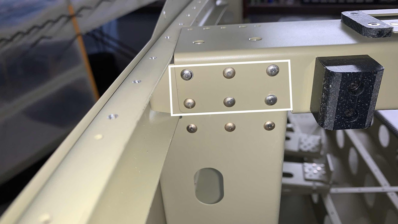
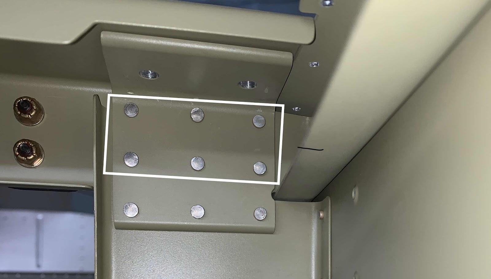
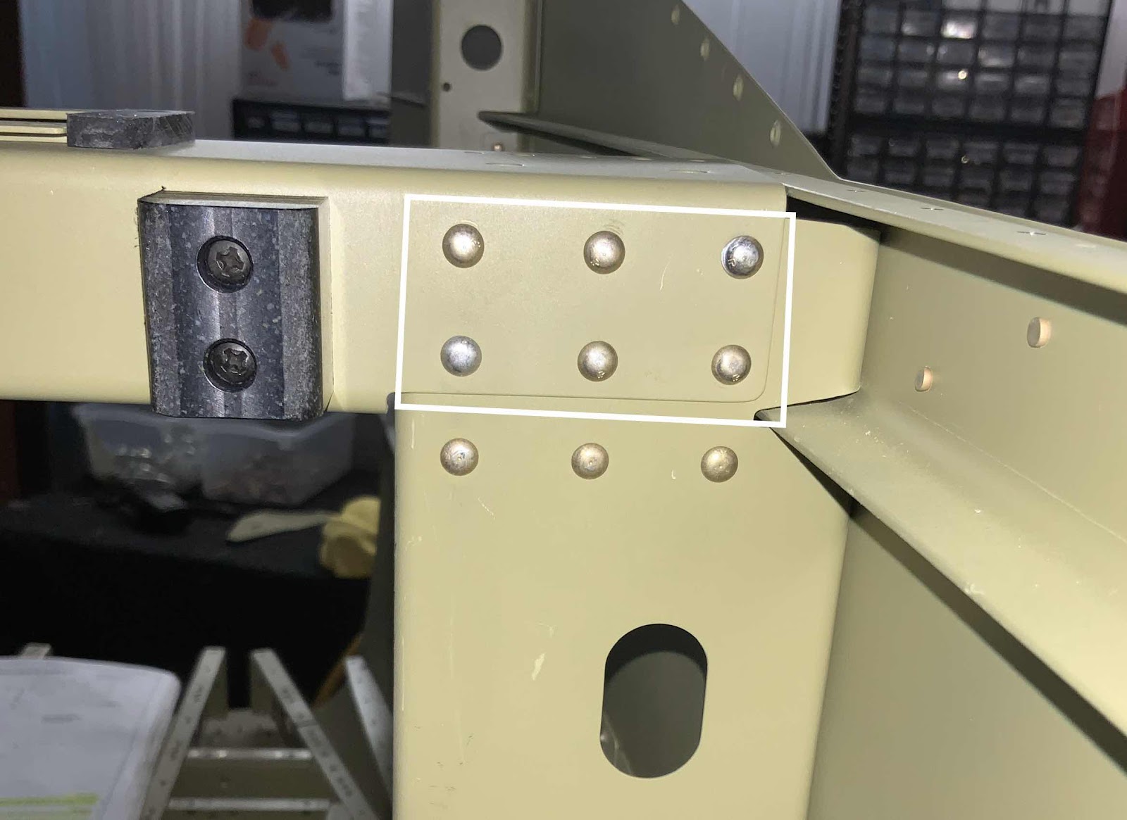
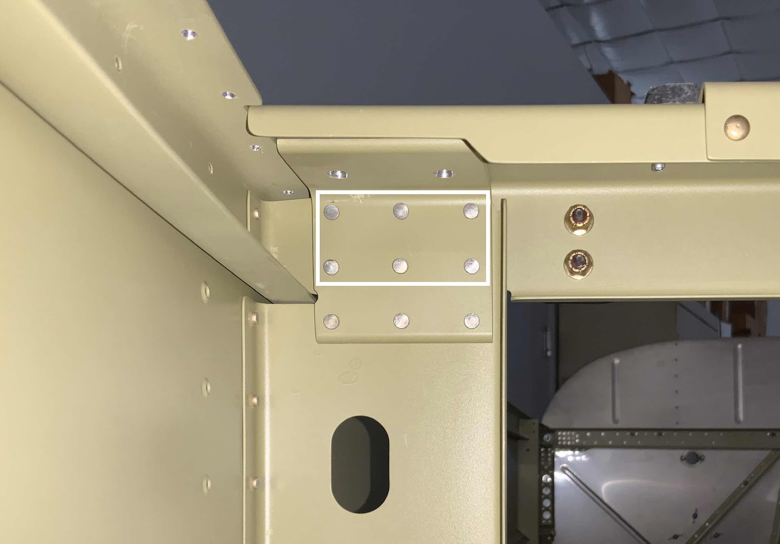
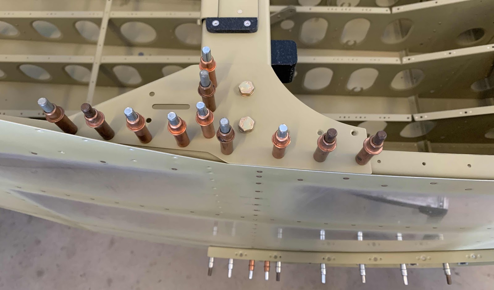
The next step was to cleco the Gussetts into place with the Upper Longerons and Brace as shown below (right side in the first picture, left side in the second) and temporarily install the two bolts (you can see the two bolt heads).
I started the riveting process for the Gussetts, but didn’t get very far. I will pick it up here during the next session.
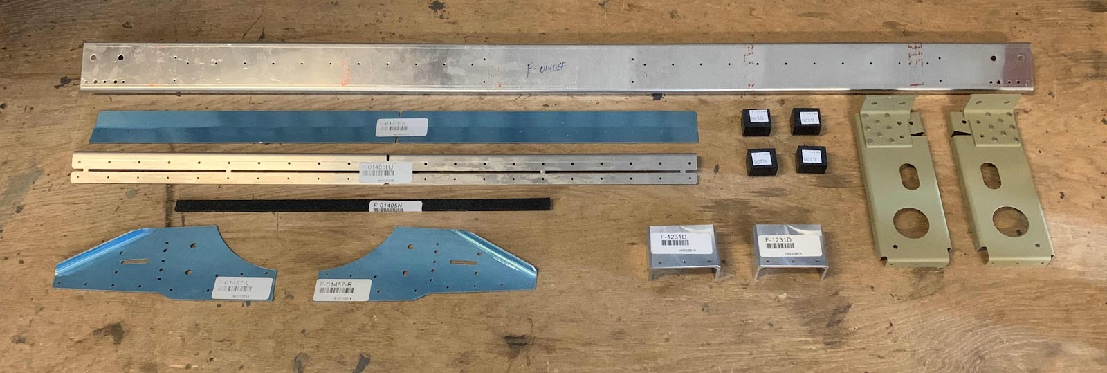
Here are the nine parts after the Akzo primer has dried.....now, let’s rivet stuff.
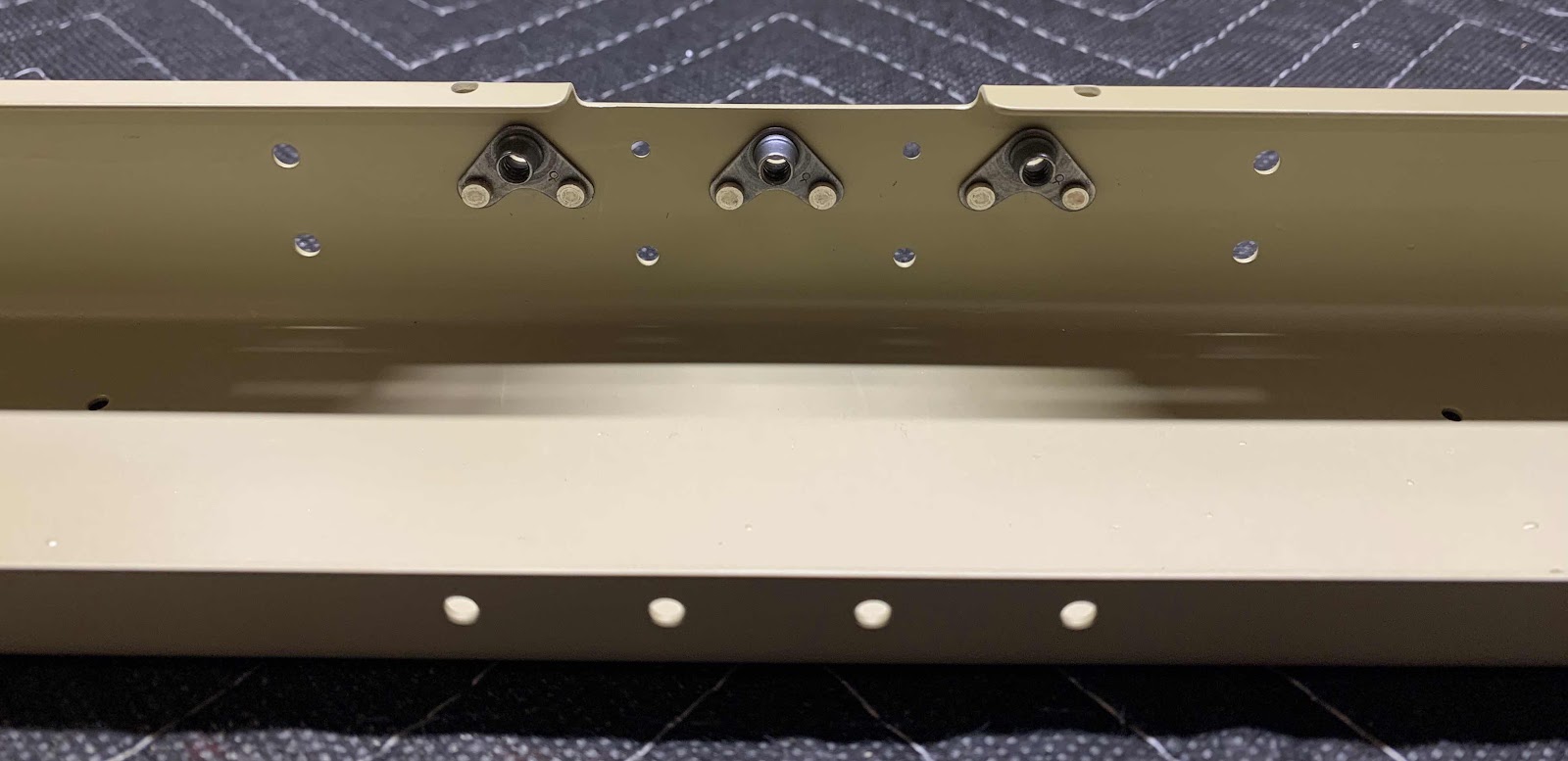
To begin, the three MS21055L08 nutplates were installed on the F-01405F Brace using two AN426AD3-3 rivets. This is the aft side.....
.....and the forward side.
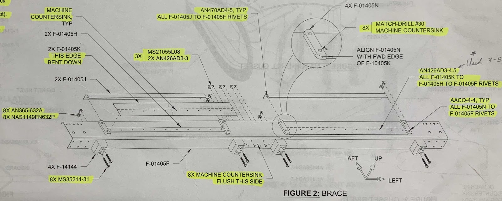
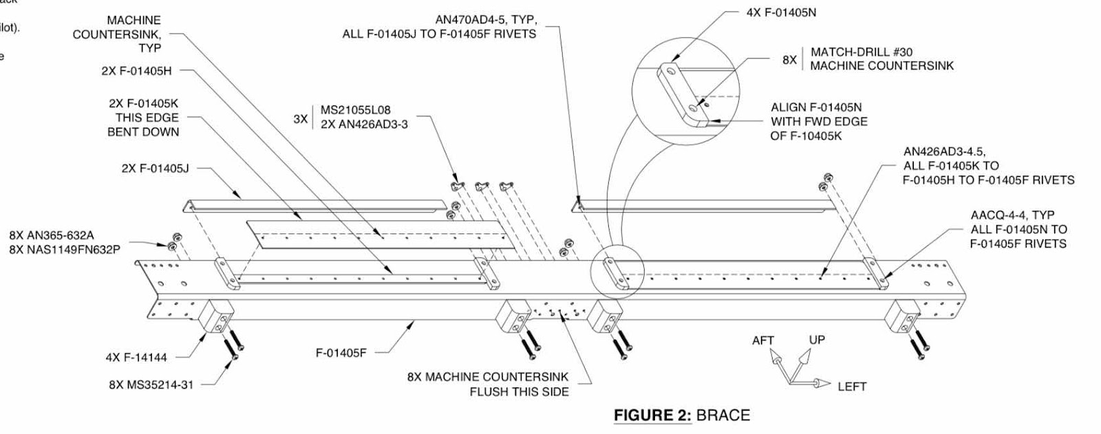
This is the diagram from the plans on how to put all these pieces together.
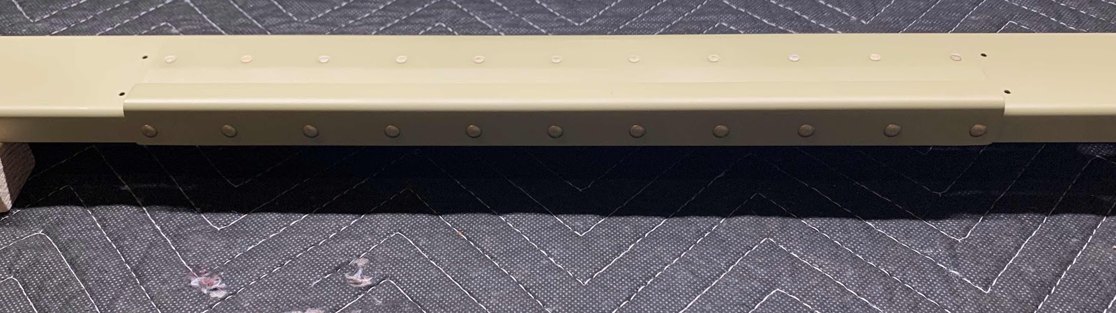
The picture below show the four total pieces....three you can see and one you can not (F-01405H Shim). The F-01405F Brace is the biggest piece. The row of rivets in the front of the picture (rear as it is installed on the plane) are 11 AN470AD4-5 attaching the F-01405J to the Brace. The back row of 11 AN426AD3.5 rivets are attaching the F-01405K Guides to the Brace (with the F-01405H Shims in between). All of these rivets were set with my pneumatic squeezer. This picture shows the manufactured head of the rivets.....
.....and this one shows the shop head side of the rivets.
These two pictures only show one side of the Brace. The other side was completed using the same parts, pieces and rivets.
That was all the work I was able to accomplish tonight, so I will start here during the next session.
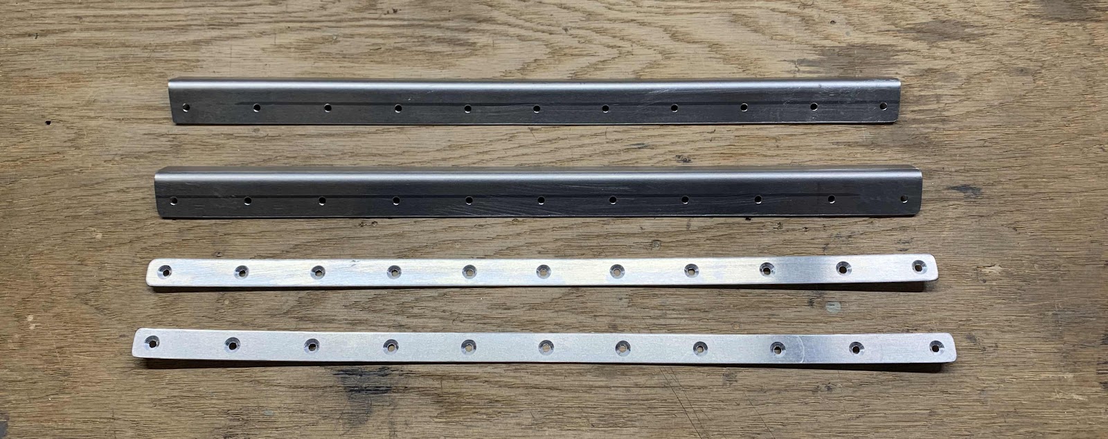
Tuesday’s session was very productive. In the picture below, the two pieces on the top (F-01405J - Angles) and the two pieces on the bottom (F-01405H - Shims) had the holes deburred and edges cleaned. The holes in the Shims were also countersunk.
These are the two F-01405K - Guides. These two pieces also had the edges cleaned and the holes beburred and dimpled.
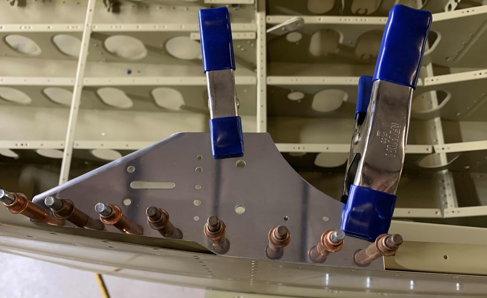
Below is the left F-01457 Gusset (the right gets prepared the same way). To start, the Gusset gets clecoed to the Upper Longeron with the #40 hole and is “rotated” until it overlaps the outboard edge of the Side Skin. Once it is in the correct place, it gets clamped to the Upper Longeron and the eight holes (where the clecos are installed) were Final-Drilled to #30 and the two bigger holes (by the blue clamp) were Final-Drilled to 1/4”. Again, this is the left Gusset.....
.....and here is the right Gusset.
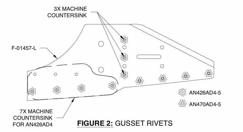
The last step in preparation of the Gussets, is to countersink the 10 holes as shown in the plans excerpt.
I decided to wait until I had help to install the rivets on the bottom of the Side Skin to the Lower Longeron. I could probably do it myself, but it would definitely be easier with a second set of hands.....and probably produce a better end result. So, I wait.....
In the meantime, I continued on to the next set of instruction in this Section. All of these parts.....
.....will go together like this to make the Brace.
To start, I cleaned the edges of the F-01405F Brace and deburred all the holes. Hard to see in the picture below, but the eight holes on the front side were countersunk to accept the head of an AN426AD3 rivet.
Lastly, the four F-01405N Seat Back Adjustment Guides were fabricated following the instructions below. The four completed pieces are shown in the picture above.
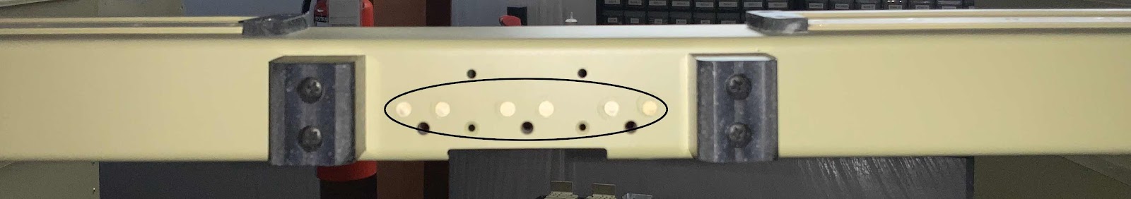
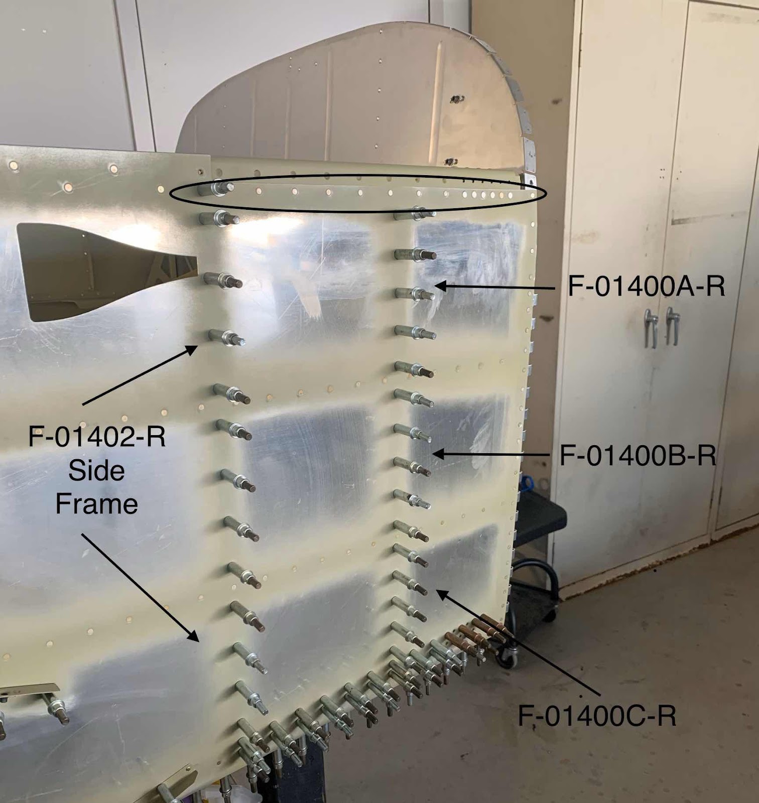
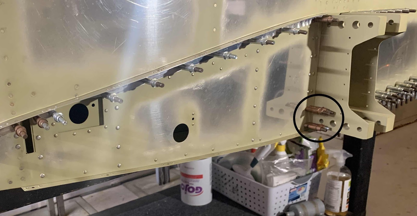
Back to work on the Right Side Skin. I continued moving forward toward the Firewall. In the picture below, you can see the rivets installed in the Longeron (circled) and the Firewall (more on that below). You can’t see from this angle, but the F-01402-R Side Frame and F-01400A & B & C-R Stiffeners are clecoed into place on the inside of the Right Side Skin.
Here is the outside of the Firewall with the right side Piano Hinge.....
.....and the inside.
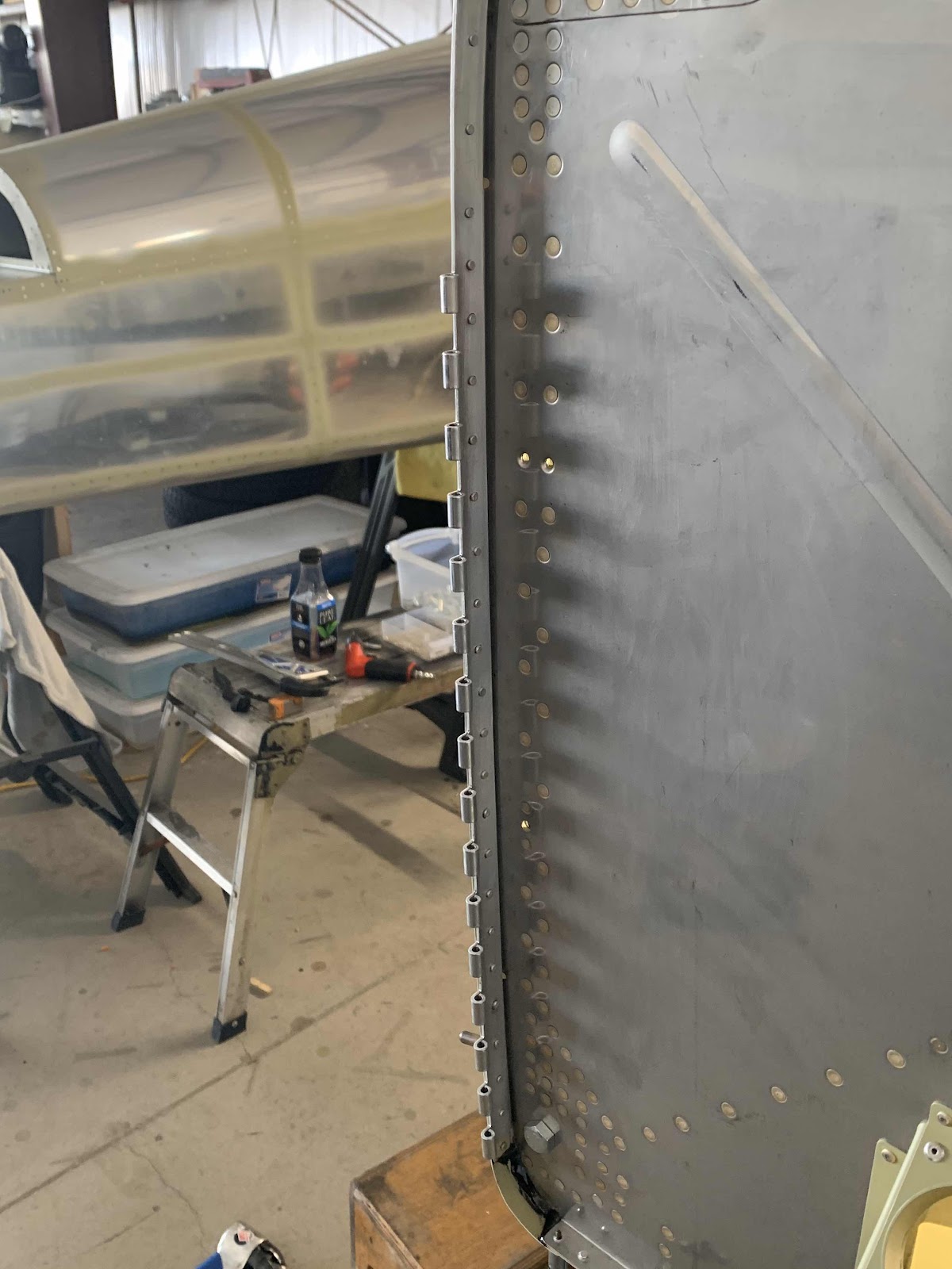
Next, I clecoed the Wing Root Fairing into place on the Right Side Skin. However, I decided to wait on installing the nine K1100-08D nutplates until after the Fairing is riveted to the Side Skin. The plans only have you install certain nutplates initially, and the rest after the Fairing is attached to the Side Skin, but I found a few nutplates to still be a little in the way when I completed the left side. They will be pretty easy to install later.
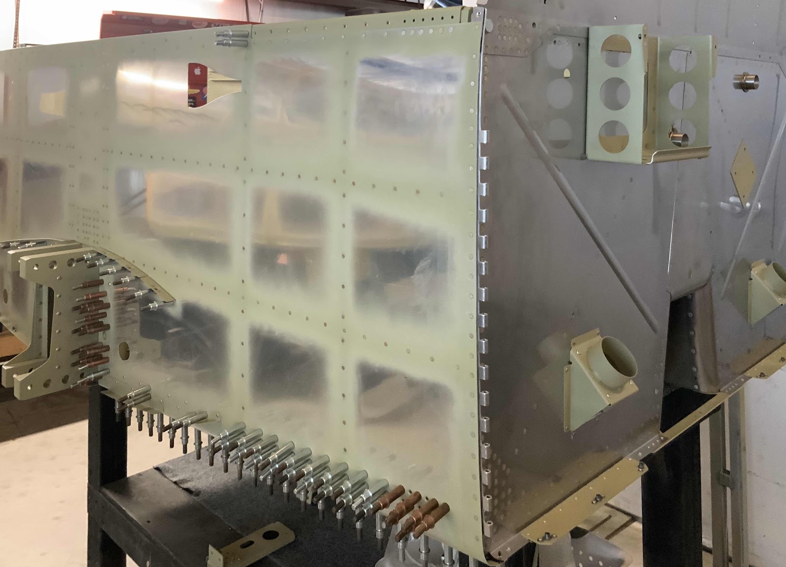
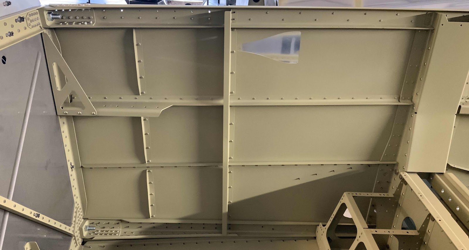
This is the inside of the Right Side Skin showing the Side Frame and Stiffeners mentioned in the opening paragraph. Everything fit together perfectly.
This is a close up of the where the Upper Longeron Assembly is temporarily bolted to the Firewall and the associated rivets.
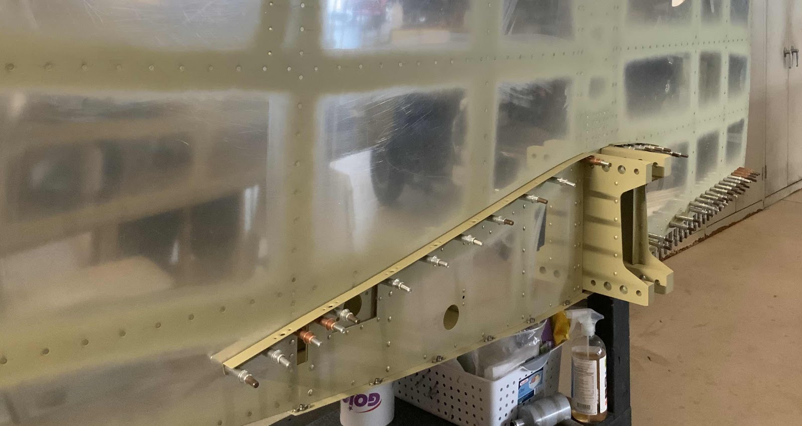
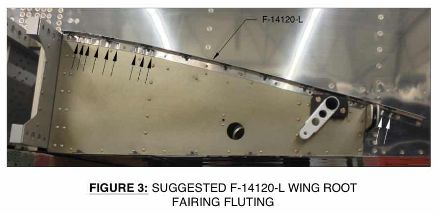
Another LONG build session.....I started today’s session by treating the F-14120-R Root Fairing Attach Angle (pictured below) and the F-01487-R Center Section Channel (seven pictures down) with Alumiprep, Alodine, and Akzo primer. I previously did not treat this Root Fairing because it would need to be fluted.....and I wanted to wait for the Right Side Skin to be installed to get a perfect fit. I also wanted to flute the Fairing PRIOR to priming it. The small excerpt shows where Van’s recommends the fluting to be done. I followed their guidance by putting the flutes in these locations and it worked perfectly. I did have to take the Fairing off a couple of times (just like on the Left Side Skin) to make the flutes a little “deeper”. I circled the area of the flutes below. Other than that, it worked out great.
While those two pieces were drying, I installed the seven K1000-08D nutplates to the F-01484 Bottom Skin using my hand squeezer. In the picture below, you can see six of the nutplates pretty easily.....the seventh is circled in black between the F-01403 and F-01404 Bulkhead Assemblies.
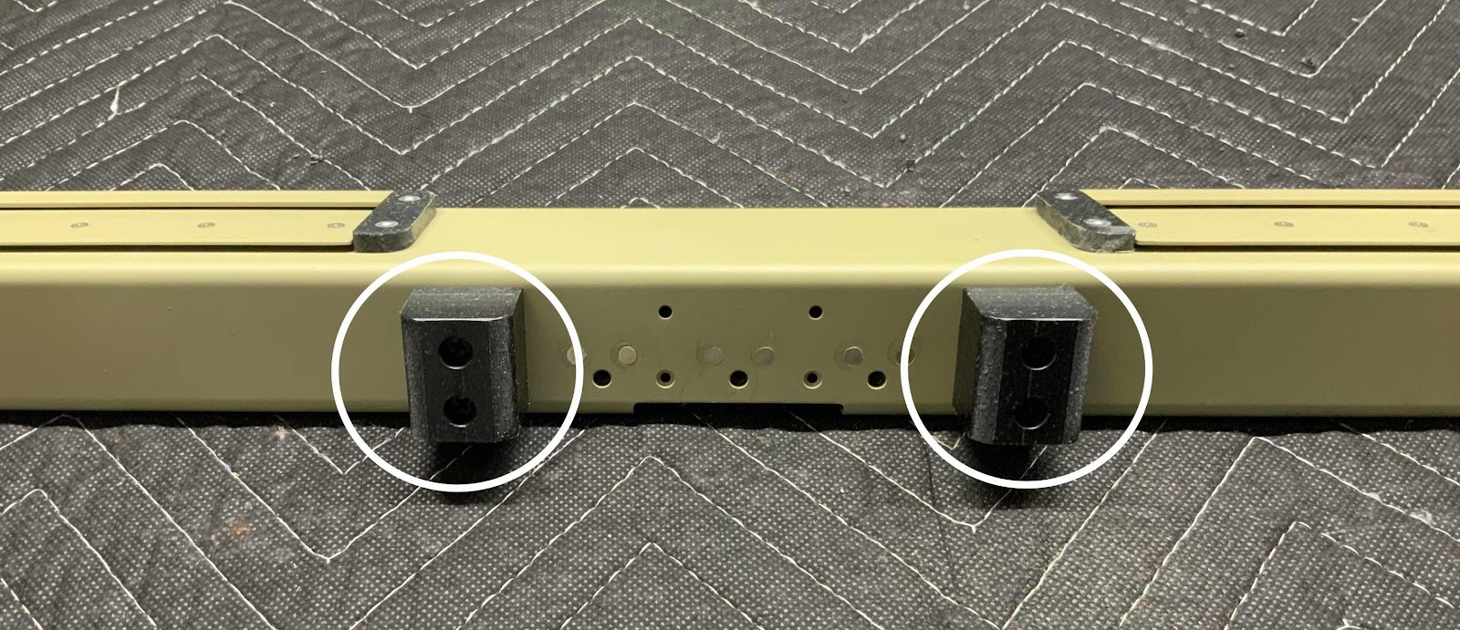
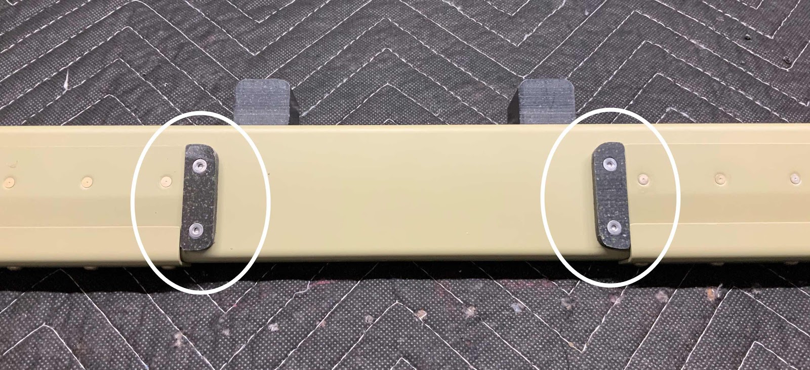
When I originally started installing the Right Side Skin (starting in the center and working aft per the plans), I skipped the four rivet locations (circled below) because I thought I needed help to install them. Reaching to arms length on either side of the Side Skin with the bucking bar in my left hand and the rivet gun in my right (with a 5” set to clear the Bulkhead Assembly).....I thought would produce rivets with “smilies” on them or screw up the shop head on the opposite side. Well, after some head scratching and practice, I was able to install them myself.....with NO SMILIES AND GREAT SHOP HEADS!!! So, I did....circled in white above.
Next up.....installing the F-01463 Web Stiffeners using AN470AD4-5 rivets with my pneumatic squeezer to the insides of the F-01403 & F-01404 Bulkhead Assemblies. The two pictures below show the manufactured and shop head sides of each Stiffener.
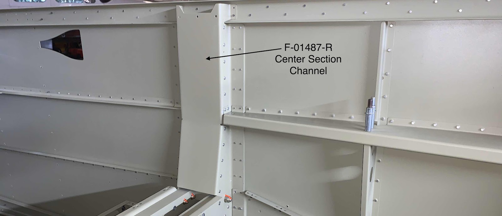
I started today by treating the F-14120-R Root Fairing Attach Angle and the F-01487-R Center Section Channel. Below is the Center Section Channel. This Channel was installed using LP4-3 bling rivets. This is the aft side of the Channel.....
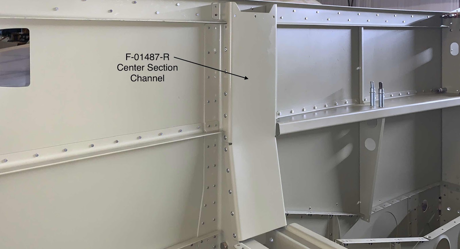
.....and the forward side of the Channel.
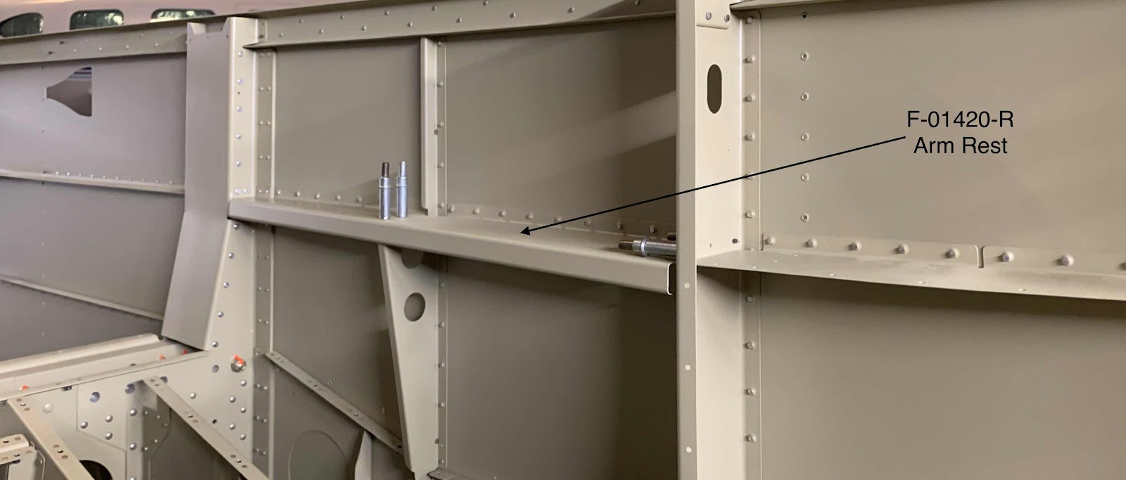
The F-01420-R Arm Rest was the next part to get installed. The Arm Rest is shown here riveted to the Side Skin and Center Section Channel. Rivets will need to be installed in the locations of the clecos to finish the install and tie all the Ribs together.
I continued moving forward from the Center Section toward the Firewall. I installed rivets in the horizontal rows up to the vertical row identified below. PRIOR to installing the rivets on the Side Skin to Upper Longeron and Firewall, proseal will have to be used between the parts in the locations shown in second picture below. So, I had to stop at this vertical row of rivets to allow the Skin to be “pulled” out enough to get the proseal in the seams.....just the right distance.
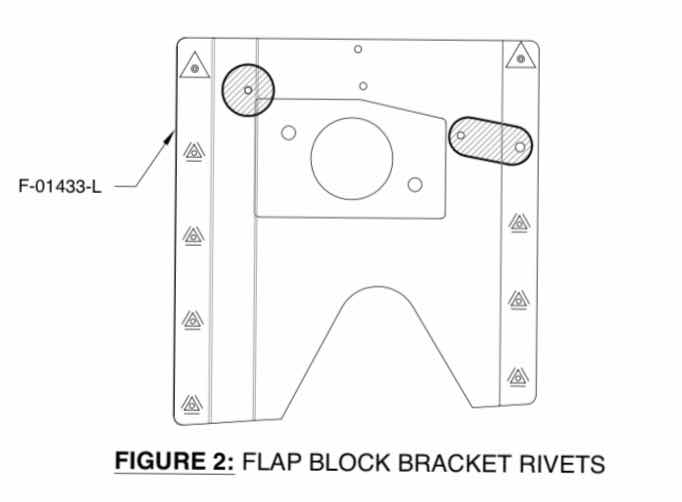
I worked a rather short session tonight.....only installed nine rivets (seven AN470AD4-5 and two AN426AD3-4). I installed the right Flap Block Bracket with the rivets shown below. (Just a reminder: Unless otherwise noted, Van’s only shows plans for the left side build (the right side is usually a mirror of the left—again, unless otherwise noted). So, the excerpt (left side) and the two pictures below (right side) will look backwards.
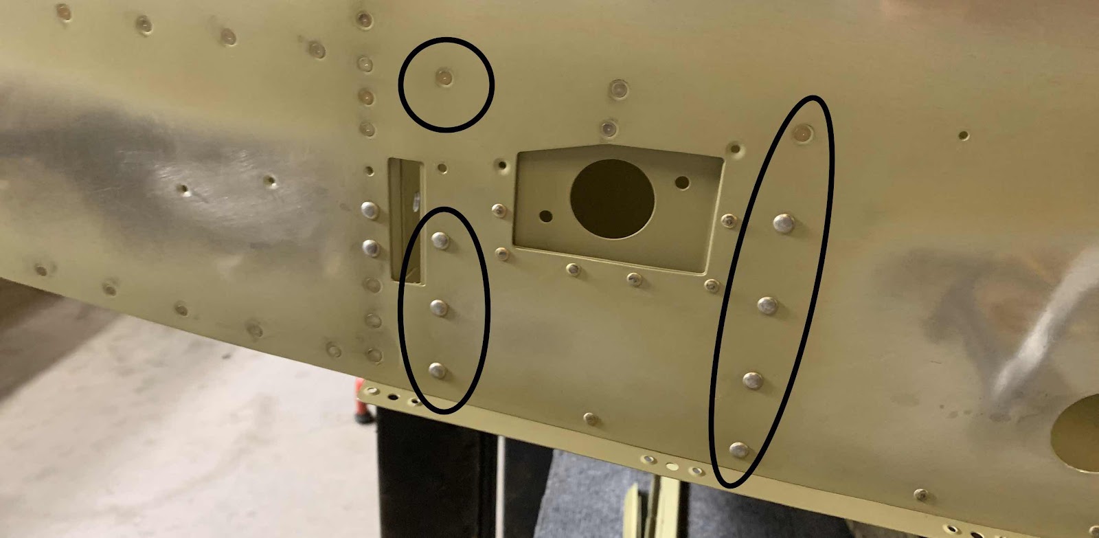
Here are the manufactured heads of the nine rivets on the outside of the Right Side Skin.....
.....and the shop head side of those nine rivets on the inside of the Fuselage.
Well, that was pretty much it for tonight. I will continue installing the Side Skin “forward rivets” during the next session.
Alright! It’s time to update my blog! It has been WAY to long since my last update, but I have completed A LOT of work! I will do my best to update the blog with all the work over the past month. I will start with my most recent work competed and work my way back to November 7 (my last blog posting). So, here goes......
Wednesday, December 11, 2019 (Part 29)
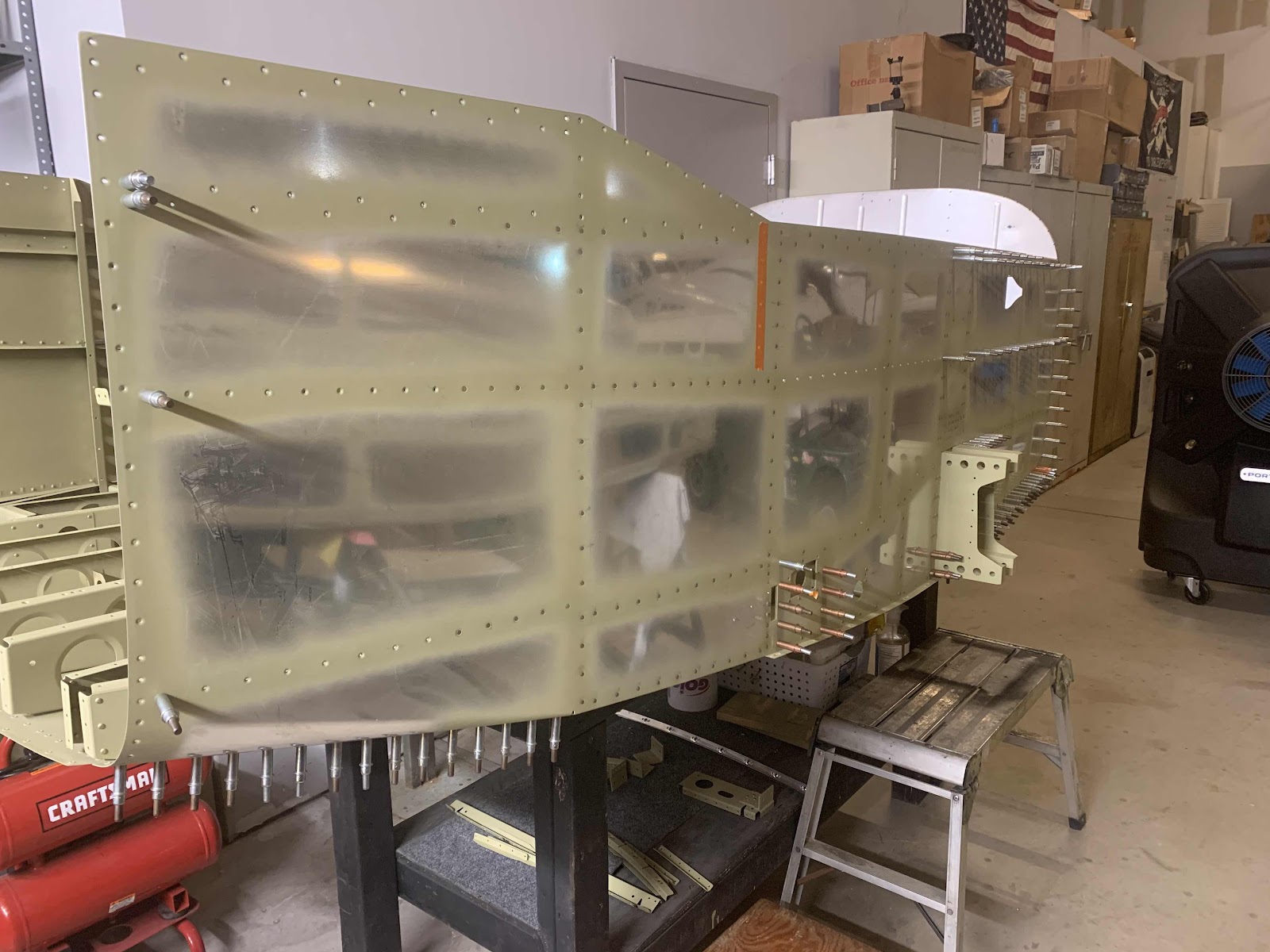
I continued installing rivets on the aft portion of the Right Side Skin. As the plans direct, rivets are initially installed on the F-01403 (Forward Center Section Bulkhead Assembly) and the F-01404 (Aft Center Section Bulkhead Assembly) and installed aft, then forward (just like on the Left Side Skin). I have installed all the rivets in the Aft portion except for the bottom portion where you see clecos. This is where the F-10433-R Flap Block Bracket will be installed to the Fuselage.
Up until this point, I have been able to install all the rivets myself. However, there are a four rivets by the lower Aft Center Section that I will need help installing.
I will continue working on the Right Side Skin during the next work session.
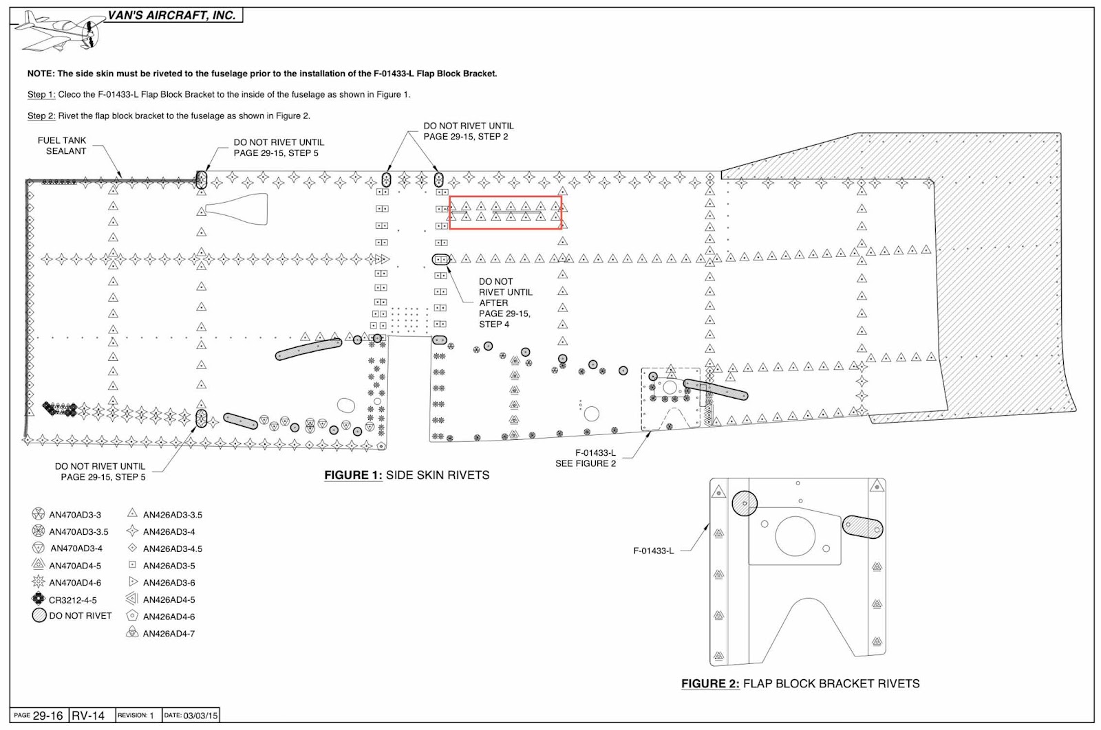
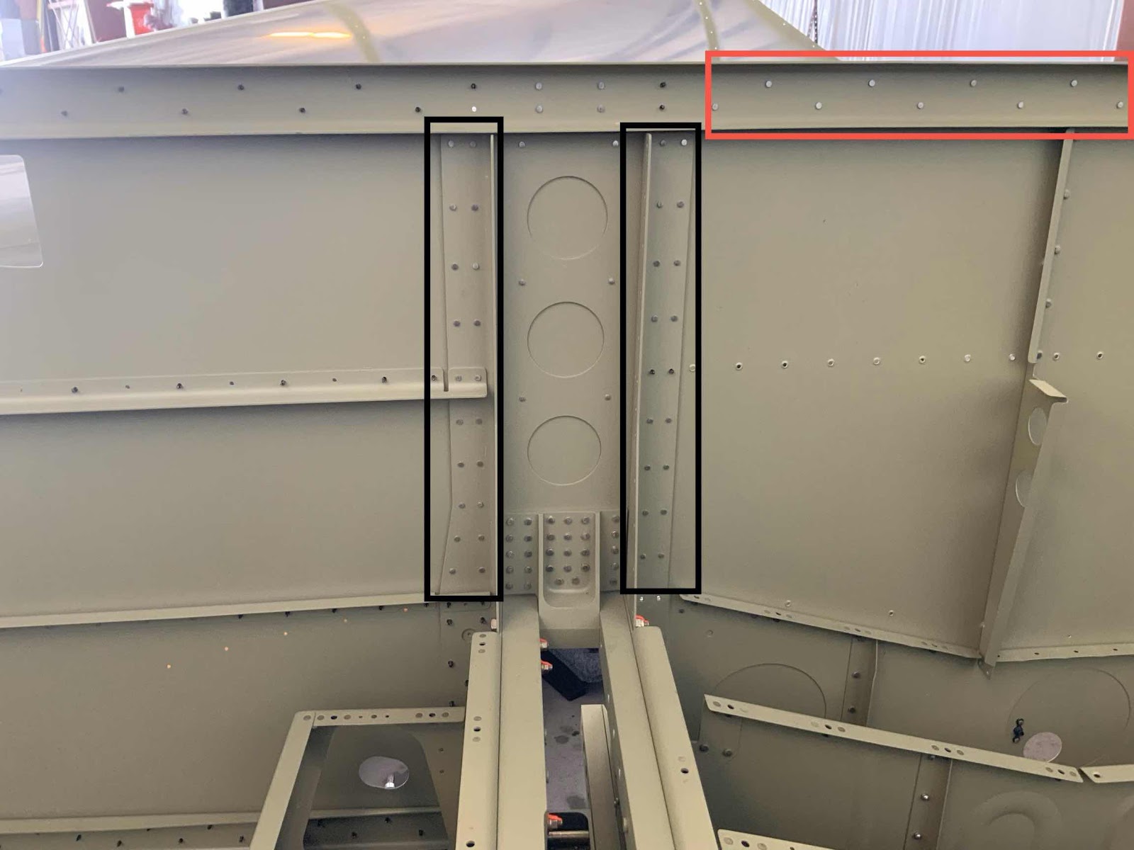
After the LONG, LONG work day on Sunday, it’s now time to repeat the process from the Left Side Skin and start installing all the rivets in the Right Side Skin. The photo below shows the rivet legend for the Left Side Skin (as previously posted). With the exception of the rivets in the red box (Canopy Latch Brackets—only installed on the left side), the Right Side Skin rivet installation will be identical.....“just opposite”!!
The two black boxes below show the locations where the initial rivets for the Right Side Skin were installed in the Forward & Aft Center Sections (as directed in the plans). The red box shows where I started installing rivets aft of the Center Sections in the Upper Longeron. As you can see from the rivet legend, a mixture of AN426AD3-5 and AN426AD3-4 rivets were used up to this point.
Because I prepared most of the internal parts (Ribs, Stiffeners, etc) that accompany the Side Skins during installation, the assembly of the Right Side Skin “should” go faster. As I mentioned in an earlier post, I decided to prepare all the internal parts (edge cleaning, hole deburring, Alumiprep, Alodine, primer, etc) for the Side Skin assemblies at the same time. It definitely makes for much faster work to retrieve an already completed part when the plans call for it.
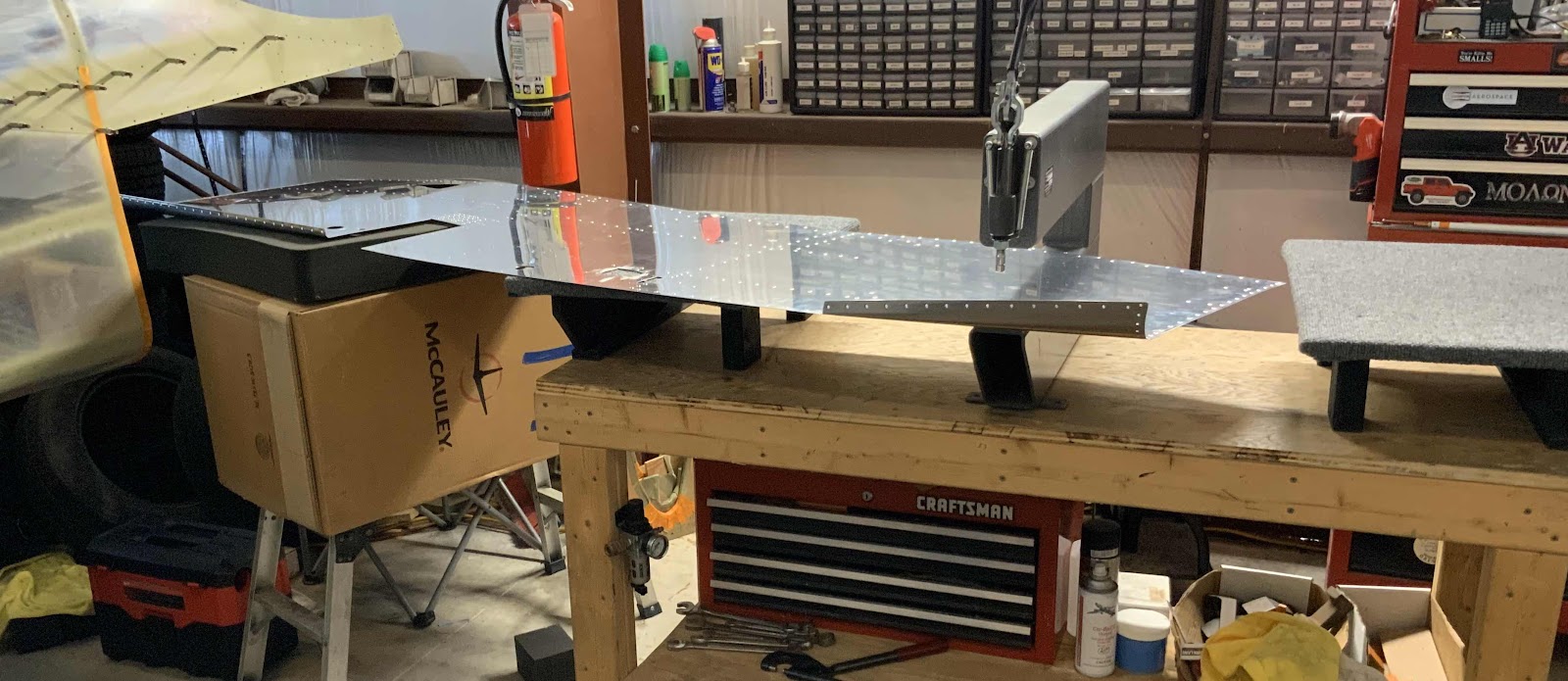
However, I still needed to prepare the Right Side Skin itself. So, the edges had to be cleaned and certain edges received a lap joint, the holes were deburred, the appropriate #30 and #40 holes were dimpled using the DRDT-2 and my pneumatic squeezer, and the Skin was treated with Alumiprep, Alodine, and Akzo primed. In the picture below, you can see my set up for the dimpling the Skin. Because the Skin is so long, I used a step stool, McCauley box, and pelican case foam as my second set of hands....worked out great!
Once all that was done (and the primer was dry), I started riveting. Most of the riveting done from here on out is the exact same thing as with the Left Skin. The only difference I see is the addition of the Canopy Latch Brackets on the Left Skin.....everything else is essentially mirrored from one side to the other.
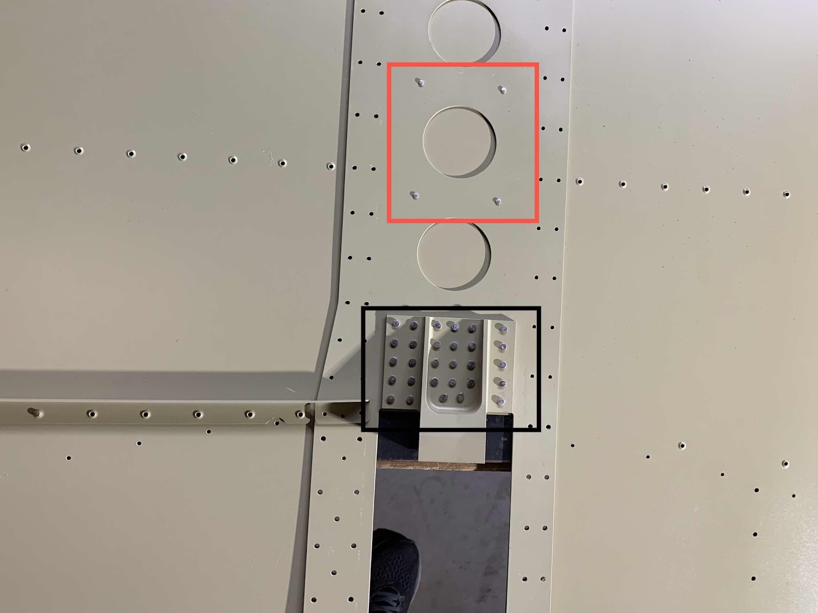
To get started, the F-01485R Center Section Side Plate was backriveted to the Right Side Skin (you can see four of the six AN426AD3-3.5 rivets in the red box). The next step was to backrivet the F-01464-R Upper Drag Fitting (in the black box below) using five AN426AD4-8 and 24 AN426AD4-7 rivets.
The next step in the plans is to rivet the F-01413-R Stiffener to the Right Side Skin using 18 AN426AD3-4 rivets. (The plans called for AN426AD3-3.5 rivets, but they looked a little short to me. I measured the -3.5 and -4 rivets and the -4’s measured perfectly.....so I used -4’s here for the installation). As directed in the plans, the five holes closest to the Center Side Plate did not have rivets installed at this time. This will allow the Skin to be “pulled out slightly” when it is placed on the Fuselage for final install.
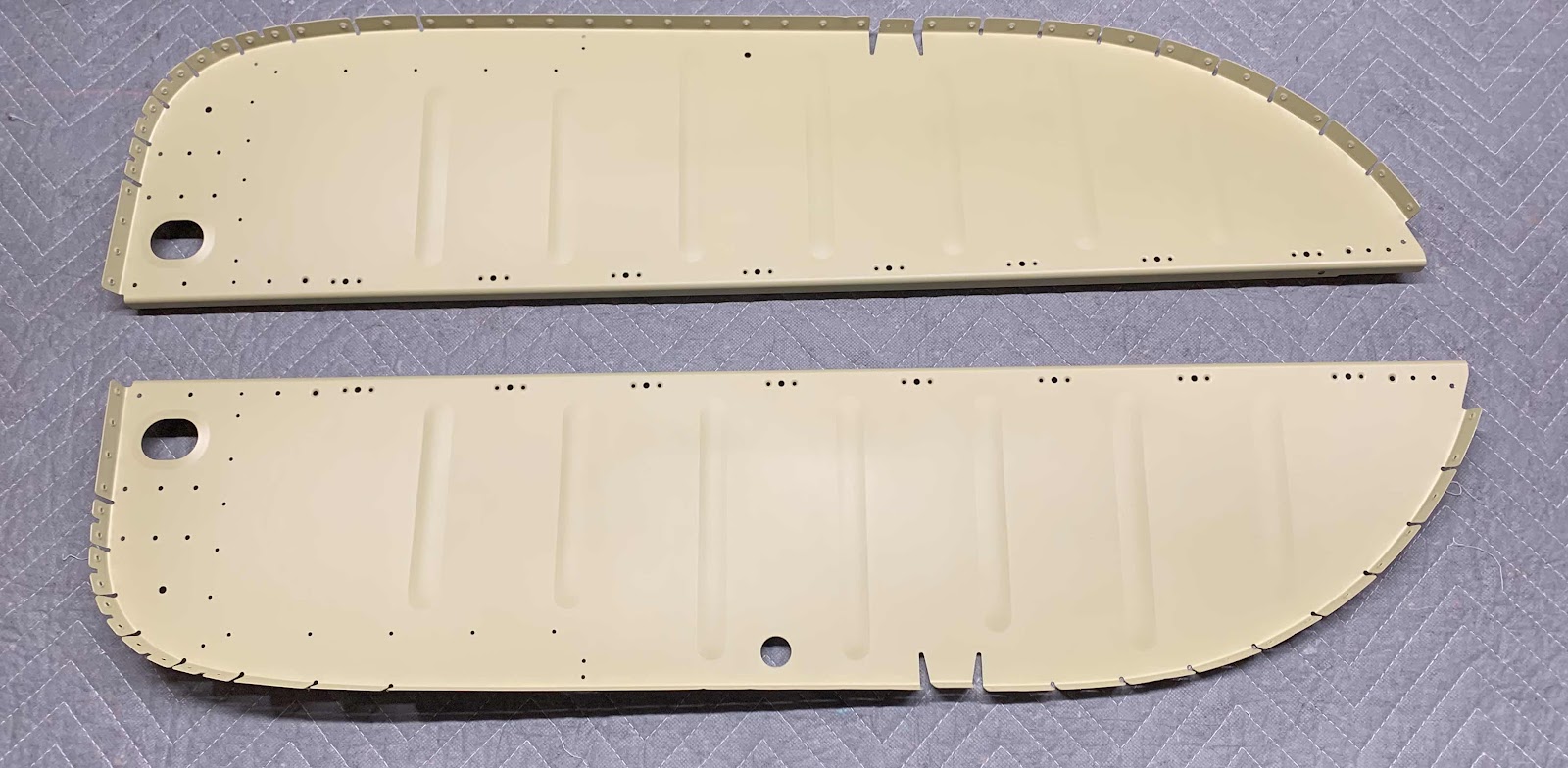
The next two pieces to get riveted to the Right Side Skin were the F-01491-R (top) and F-01492-R (bottom) Fuselage Side Ribs. Not the best picture showing the installed rivets, but AN426AD3-4 rivets were used (measured perfectly compared the the 3-3.5 rivets called for in the plans). Only the first five holes received rivets at this time....the remaining nine holes will be used when the Rear Fuselage is attached.
Once those five pieces were riveted into place on the Right Side Skin, it was time to “set” it into place on the Fuselage. As I mentioned earlier, the five holes closest to the Center Section Side Plate did not receive rivets. Here is why:
“Step 3: Rest the side skin on top of the center section as shown in figure 1. The side skin will be forward and high of the final position”
Step 4: Bend the forward portion of the side skin outboard slightly to allow the aft portion of the F-01413 Stiffener to clear inboard of the F-01403D-R Forward Center Section Angle, then move the side skin aft to align the center section notch with the center section.”
Once in position, the Upper Longeron Assembly was clecoed to the Side Skin. Finally, the Side Skin was clecoed to the Fuselage. This the Right Side Skin clecoed into place on the Fuselage.....


 ``````