This blog was created to memorialize the building process of my Van's Aircraft RV-14 and to satisfy the requirements for certification in the Experimental Amateur Built Aircraft category. It will also serve as a central location for ME to reference in the future on processes and techniques I used during the build. Additionally, it will allow my family, friends, and other interested builders the opportunity to follow along during my build…..and might be helpful to someone along the way.
I continued setting rivets in the Side Skins.....damn there are a lot of rivets!!!! With the exception of a few rivets I’ll need some help with, the three rows of rivets have been installed. The last remaining row in the very bottom that attaches the Side Skin to the Bottom Skin.
Here is a shot of the inside of the Right Side Skin showing some completed rivet locations.
I received the hardware order from Van’s that included additional K1100-06 Nutplates and AACQ-4-3 blind rivets. I started today by installing the F-01497A and F-01497B Rudder Cable Guides on the Right Side Skin. The picture below shows the #30 holes that were previously prepared and dimpled.
This pictures shows the completed installation of the Cable Guides on the Left Side Skin using AACQ4-4 and 4-3 bling rivets. The Cable Guide on the Right Side Skin looks the same.
In Part 34, I started the installation of the Cable Guide in the Left Side Skin using AACQ4-4 rivets for all six rivet locations. Becasue the F-01497B section of the Guide is about 1/2 the thickness of the F-01497A, the AACQ4-4 rivets were to long after being set. In the picture below, you can see the longer AACQ4-4 (installed on Left Side Skin) and the shorter AACQ4-3 (installed on the Right Side Skin). I didn’t like the result of the larger 4-4 rivets, so I used the shorter 4-3’s on the smaller pieces.
Here are both of the Cable Guides installed on the Left and Right Side Skins with the 4-3 rivets installed on the smaller pieces.
I installed the remaining five K1100-06 nutplates on the Access Panel. Again, because I chose countersunk screws for the Cover Plate installation, the top two holes on each side had to be countersunk to accept the dimpled holes of the Plate. You can see the freshly countersunk holes through the Left Side Skin and Longeron. The Right Side Skin looks the same and I will eventually put primer on these holes for rust protection.
The clecos are becoming fewer. On this side, I only have the very bottom row of rivets to install that attach the Right Side Skin to the Bottom Skin.
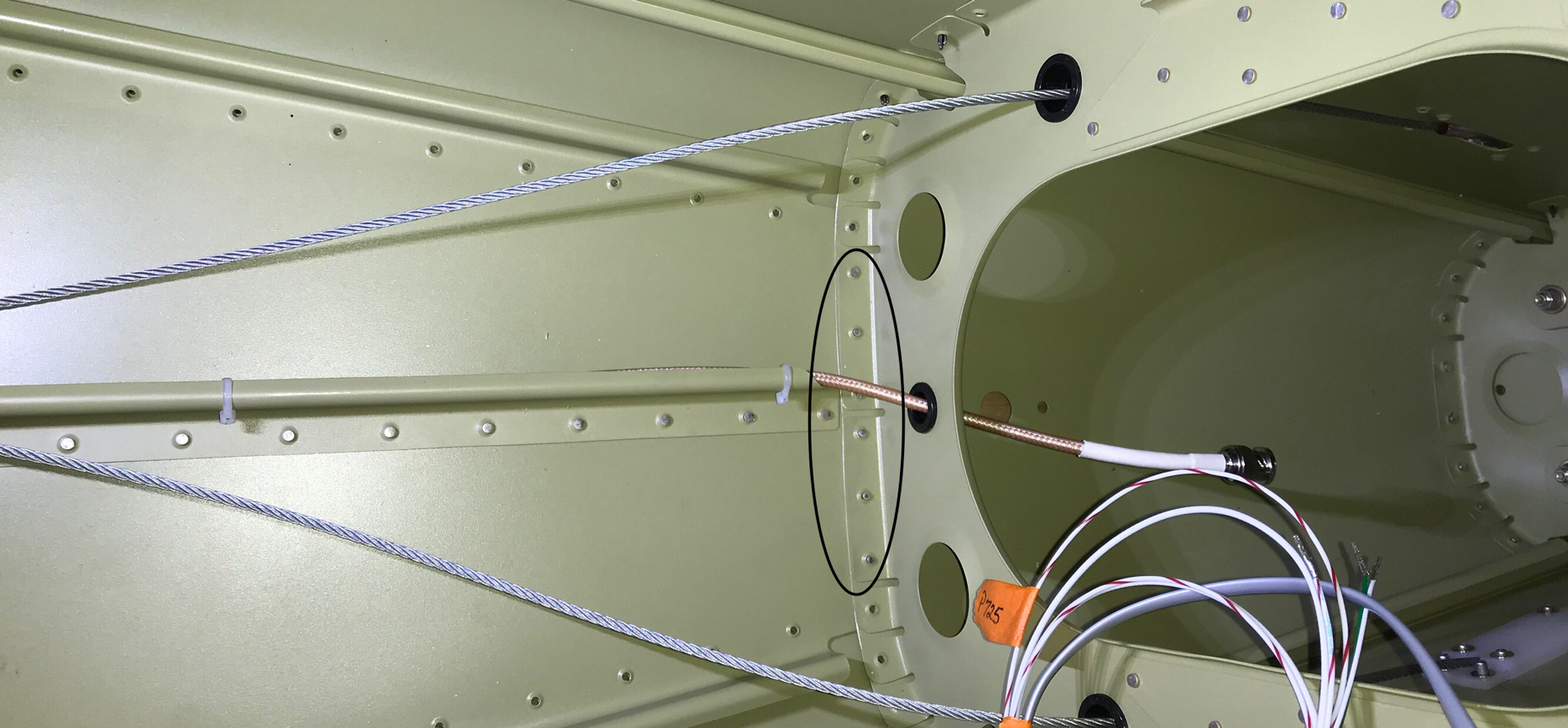
The work completed in the picture below was actually accomplished yesterday (9/27/17). I didn’t enter the blog post prior to midnight, so it was posted on the following day. Anyway, no big deal. I completed the rivets in the Left and Right between the F-01408 and F-01407 Bulkheads (circled in black). I only took a picture of the Left Side Skin, but the Right Side Skin looks the same.
The work completed below was completed today (9/28/17). I continued making progress riveting the Side Skins. I installed the rivets between the F-01407 Bulkhead and the forward end of the Side Skin. Circled below is the location the rivets were installed and shows the Right Side Skin. The Left Side Skin looks the same.
Here is the Right Side Skin showing a majority of the rivets attaching the Side Skin to the F-01486A-R Stiffener (horizontal row of rivets).
I moved on to installing the rivets in the Right Side Skin and the F-01411 Bulkhead (vertical circle). Lastly, the rivets attaching the Right Side Skin, F-01486B-L Stiffener, and F-01479 Aft Bottom Skin we’re installed. The plans called for the use of AN-426AD3-4 rivets, but I found them to be a little too short. So, I installed 3-4.5 rivets and I liked the results. I will also use 3-4.5 rivets for the remaining location that attach the Aft Bottom Skin.
I included the session hours for both session in the totals below:
I riveted the bottom few rivets on the Side Skins and the Aft Fuselage Bottom Skin. Pictured below is the right side of the Fuselage. The Right Rudder Stop has also been installed into place using four AN426AD4-6 flush rivets. All of these rivets were pains in the a**. The area is very small to work in and hard to get a bucking bar behind the rivets. My buddy Jeff had to help me out as these rivets were definitely a two dude job.
The two rivets circled below are the shop heads of the rivets attaching the Rudder Stop. The other two rivets are on the other side of the Bulkhead.
I installed many more AN426AD3-3.5 on the Right Side Skin. The horizontal row of rivets in the center of the picture are attached to the F-01486A-R Stiffener. I used a rivet gun and bucking bar to set all of these rivets.
The upper horizontal row of rivets are attached to the F-01418B-R Longeron. I used my pneumatic squeezer with the 2” longeron yoke to set these rivets.
Since I’m following the plans and riveting the Side Skins from top to bottom (and back to front—my decision), I decided to go ahead and install the nutplates into their appropriate locations as I move along. There are two types of nutplates installed in this section. The first are K1100-06 (center pre-dimpled) used to go over a hole that has been previously dimpled. The second is the K1000-06 (not pre-dimpled) to go on a flat surface such as on a Longeron. However, either of these nutplates can have their attach holes dimpled for different applications.
In the picture below, there are six nutplates (K1100-06) riveted into place that will attach the Access Panel Covers. Each screw hole will use a #6 screw and hold the cover plate. There will also be two additional nutplates installed where the orange tape is located.
The plans call for the installation of round head screws on this Access Panel Cover, but do provide the option for flush head screws. There are a couple modifications (provided in the plans) that need to be completed for these screws. For various reasons, I have decided to use flush head screws on this Panel. If you choose the flush head screw option, you will have to order extra K1100-06 nutplates. I ordered mine from Van’s.
This is the opposite side of the same access panel showing the K1100-06 nutplates riveted into place with the shop head side of the rivet. You can also see the two locations (with the orange tape) that will accept the last two nutplates.
The picture below shows three of the K1000-06 nutplates installed on the inside of the Left Longeron. These nutplates will ultimately be used to attach the Empennage Fairing.
There are still TONS of rivets to be installed in the Side Skins! So, more to follow......
Today, I resumed riveting the Side Skins. The Skins will be riveted with a combination of AN426AD3-3.5, AD3-4, AD3-4.5, and AD 4-4 rivets. Here are the rivets around the access panel on the Left Side Skin. The holes with the orange tape are for nutplates and will be installed/riveted later.
This is the access panel on the Right Side Skin.....
I made pretty good progress today with the Side Skins. This is the Right Side Skin with rivets installed in the Longeron down to the first Stringer. (You can also see the Right Static Port)
This is the Left Side Skin with rivets installed in the Longeron down to the first Stringer. (You can see the Right Static Port)
This picture shows the shop head of a few rivets installed near the Left Static Port.
All of the “prep” work has been completed and now it’s time to.....rivet, rivet, rivet!
Starting in the center and moving outwards, the F-01479 Aft Bottom Skin and F-01411 Bulkhead were riveted together with AN426AD3-3.5 flush rivets. Here are the rivets on the aft side of the Bulkhead. Due to the very small working area, these rivets had to be set with a bucking bar and rivet gun. My buddy Jeff helped me shoot these rivets.....very difficult to do by yourself.
This is the forward side of the Bulkhead. I was able to backrivet these rivets with the plate under the fuselage. The 12” backrivet set worked the best for me in this section of the Rear Fuselage. The rivets set during this step are circled in black.
Next up, the F-01479 Aft Bottom Skin, F-01478 Bottom Skin, and the F-01410 Bulkhead were riveted together with six AN426AD3-4 flush rivets. The six rivets are circled in black in the picture below.
Now for the Side Skins. A note in the plans says, “To help the skin lay down tight, rivet the flat sides first, then rivet the curved portions, working around the curve towards the edge of the skin”. So, following the plans, I started riveting from top to bottom staring aft. Additionally, not all the holes get rivets at this time and they are marked with orange tape. Here is the Left Side Skin showing the rivets installed in the Longeron.
This picture shows the opposite side.
I will continue riveting the Side Skins during the next session.
I started today’s session by temporarily attaching the U-00018 Tail Spring Mountto the F-01411 Bulkhead in the Aft Fuselage Assembly. Once the Tail Spring Mount was attached with the hardware called for in the plans, the F-01479 Aft Bottom Skin and the F-01412 Bulkhead was attached to the Aft Fuselage Assembly. I idea was to make sure the F-01412 cleared the weld bead Tail Spring Mount. In the picture below, you can see the sharpie mark I made on the Bulkhead. I used a small fine file (curved on one side and smooth on the other) to make the necessary adjustments and keep the original shape of the opening. (Excerpt from the plans is attached a few pictures below)
Once that was completed, the F-01412 Bulkhead and the F-01479 Aft Bottom Skin were riveted together. The plans call for AN426AD3-3.5 rivets to be used, but I thought they were a little to short. So, I made the command decision to use the little longer AN426AD3-4. I like the result and happy with the rivet change. Here is a side view of the pieces riveted together.
Here is the bottom view.
The next step in the plans is to rivet the U-00018 Tail Spring Mount to the F-01412 Bulkhead. Below is the excerpt from the plans shows the two rivet locations using AN426AD4-5 rivets. (The Bulkhead was previously countersunk to accept the two rivets)
The Aft Bottom Skin was then clecoed to the Aft Fuselage Assembly. Below you can see the two rivets that were just installed in the Tail Spring Mount (black circle). There was a small gap between the Tail Spring Mount and the F-01411 Bulkhead (white circle). Several spacers were included with the kit for this purpose. I used the “fatter” of the three spacers and you can see it in the white circle between the two pieces. Lastly, two AN4-6A bolts, NAS1149F0463P washers, and MS21042-4 nuts were installed attaching the Tail Mount Spring and the Bulkhead. The plans recommend orienting the bolt head aft for easeier access. This is the aft side of the assembly and the bolts can also be seen in the white circle.
This is the forward side of the assembly and you can see the nuts attached at the bottom of the picture.
This is the what the Tail Spring Mount looks like coming out off the Aft Bottom Skin. Additional trimming had to be done to make sure there was enough clearance between the two pieces. This is not as pretty as it was when I initially removed the excess aluminum. However, the Tail Spring Mount is clear of the Aft Bottom Skin. I plan on using some fine sandpaper to make the opening a little more cosmetically pleasing......particularly on the right side.
I started today's session by removing the excess material on the Aft Bottom Skin to make room for the Tailwheel Spring. During the last session, I marked the area to be removed with a sharpie. To hold the Skin still, I taped it to the work bench and used my Dremel Tool with a 1" cutoff wheel to cut close to the cut line.
Here is the Skin after I used the Dremel and cutoff wheel.
For the final trimming, I used several small fine files and 220 grit sandpaper. Here is how it turned out.....looks pretty good to me.
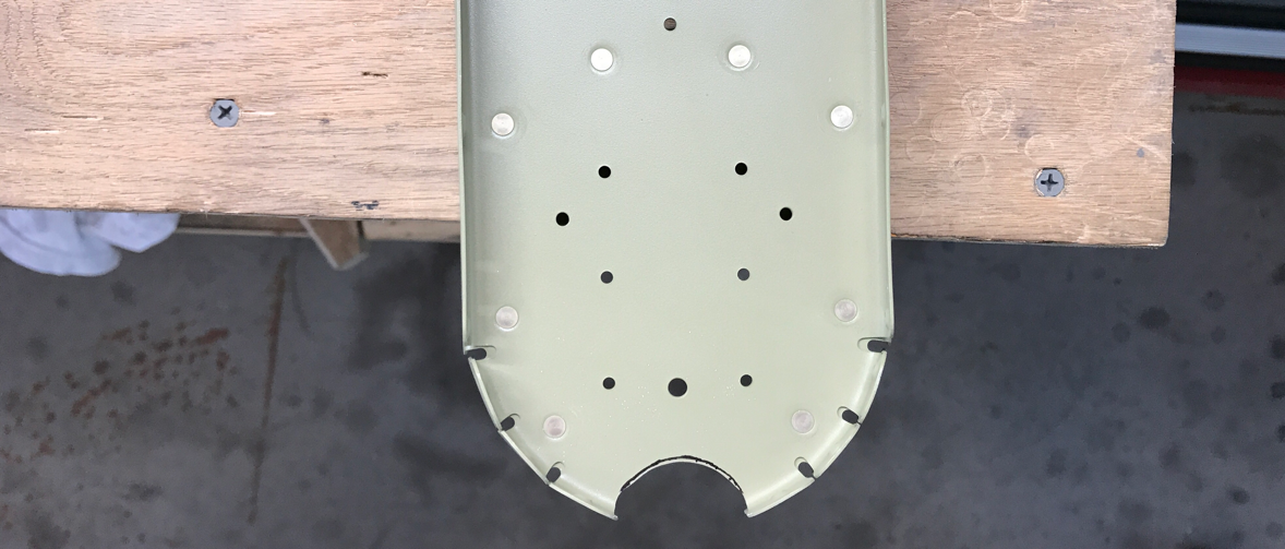
All of the #40 holes in the Skin needed to be dimpled. I used my pneumatic squeezer and a reduced diameter female die (recommended by the plans to reduce Skin distortion). There were two holes, however, I couldn't reach with the two yokes I have. So, I had to improvise. The two holes are circled below.....
And here is how I improvised.....a hammer, block of wood, small bucking bar, socket, 3/32 male dimple die, and a reduced diameter 3/32 female dimple die. I drilled a hole in the bucking bar to accept the shank of the male dimple die and taped the female dimple die to the socket.
Here was the process....
Using the concrete shop floor as support, I put the male die (attached to the bucking bar) through the hole in the Skin and the block of wood under the other end to level the Skin. The female die (taped to the socket) is put on the other dimple die and then a few hits with the hammer.....there you have it.
The prep work on the Aft Bottom Skin is complete, so it received Alumiprep, Alodine, and Priming. Tomorrow I will start riveting pieces together.....
Well, I had to go run and hide for a little bit because Hurricane Irma came sniffing around! Luckily, no plane parts were injured. So, back to the grind.....
This is the F-01479 Aft Bottom Skin and it has some excess aluminum on the sides that has to be removed.
You can't really see from the picture above, but this is the directions from the plans. The excess material that needed to be removed is the hatched areas on both sides Aft Bottom Skin. First, I used a ruler and sharpie to make a cut line alone the correct side of the stamp marks. Secondly, I used a die grinder and cutting wheel to cut along the line. Then, I used the 6" Scotchbrite Wheel on the bench grinder to clean up the cut line. Finally, 220 grit sand paper was used to smooth it all out.
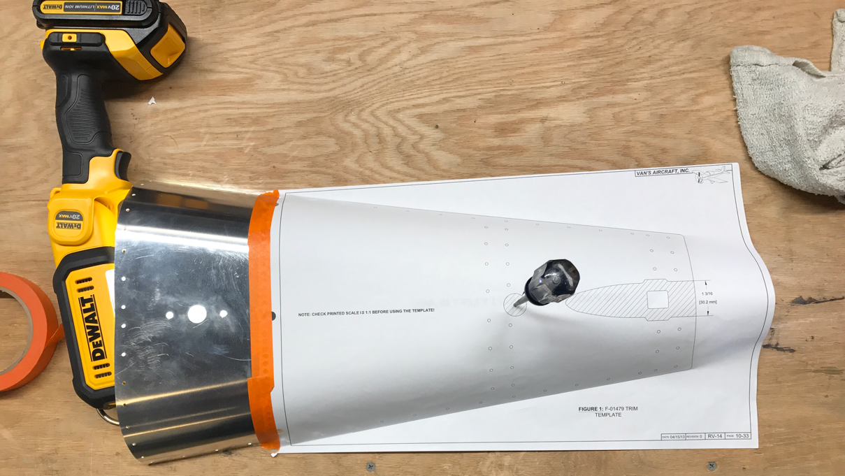
Four holes needed to be drilled in the Aft Bottom Skin as depicted in the plans below. I used a #12 drill bit on the two #12 holes and a unibit for the 9/16 and 3/4 holes. Next, is the removal of the hatched area as depicted below. This is the actual template from the plans that will be used in the next step.
Here is the template attached to the Aft Bottom Skin. It is a 1/1 scale and lines up perfectly with the pre-punched holes in the Skin. Why is the work light under there? The light shines through the pre-punched holes in the Skin and aids in the alignment of the holes in the template. Worked very well. I tucked the excess template paper under and taped it on the opposite side of the Skin. After verifying the alignment (several times), I used a new razor blade to cut out the hatched area of the template for the Tail Spring.
Once that section of the template was removed, I used to sharpie to trace the line on the aluminum. That's all for tonight.
The last system that needed installation was the Static System. The Static System that came with the Empennage Kit from Van's uses a pop rivet for the static port. I'm 100% sure that system works well, but I just wanted a little more professional and complete look. So, I purchased the Static Ports and Plumbing Kit from Cleaveland Aircraft Tool. The Static Port requires a 1/2" hole drilled with a Unibit in each of the Side Skins. Here is one of the 1/2" holes in the Right Side Skin (the Left Side Skin looks the same) and the front and rear sides of the installed Static Port. The Static Ports are bonded to the Side Skins with Proseal.
Here is a video from Cleaveland Aircraft Tool explaining the installation process.
The photo below shows the installed plumbing for the Static System in the Aft Fuselage. The plumbing is the red colored tubing running along the forward edge of the F-01407 Bulkhead and down through the Left F-01429-L Bellcrank Rib. The remaining tubing is coiled up and will be further routed into the fuselage at a later time. The black connectors will be installed on the Static Ports once the Proseal has cured.
Additionally, I installed the F-01497A (left) and F-01497B (right) Rudder Cable Guides.
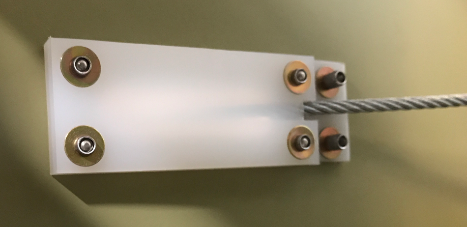
The plans call for the use of six NAS1149FN416P washers and AACQ4-4 as shown below. Here is the Rudder Guide installed on the inside of the Right Side Skin.
Here is the outside view of the installation. I'm not really satisfied with the looks of it. Because the smaller portion of the Rudder Guide is not very thick, you can see the mandrel of the rivet. It's not very cosmetically pleasing. I am thinking about drilling out these rivets and installing solid (soft) non-structural rivets instead.