Wednesday, January 29, 2020

Fuselage, Rudder and Brake System (Part 4)

In Part 2, I treated lots of parts with Alumiprep and Alodine.....here are all the parts!

The next four pictures are the parts that make up the four Brake Pedal Assemblies.  After some thought, I decided I was going to Akzo prime all the parts and then paint them gloss white (to match the WD-655-L & -R Rudder Pedals).  Once I rivet the Brake Pedal Assemblies together, I will install wing walk for an anti-slip face.

The eight CS-00018C Brake Pedal Z-Channels.....

.....the four CS-00018B Brake Pedal C-Channels.....

.....F-1052B Brake Pedal Side Plates.....

.....and the four CS-00018A Brake Pedal Pads (where the black wing walk anti-slip will be installed).

Tuesday, January 28, 2020

Fuselage, Fuel System (Part 4)

As I mentioned in the Part 1, I ordered the RV-14 Cabin Fuel Line Kit from Aircraft Specialty.  I’m not sure how much time this saved, but I bet it was significant.  Below are the four fuel lines that get installed inside the cabin.  They came from Aircraft Specialty just like you see them.....plastic red plugs  installed in each end and the lines were complete and ready to install.

The plans excerpt below shows the installation of the left fuel line that runs under the pilot.  (The right side under the passenger seat is installed the same way).

Here is the fuel line installed, as shown in the plans excerpt above, on the left side of the plane.

This is where the fuel line penetrates the Fuselage on the left side of the plane.....the AN833-6D Elbow and the AN924-6D Nut are installed here.  I put orange torque seal on the nut and installed the rubber cap on the end of the elbow.  This will prevent any debris from getting in the fuel line.

This is the right side of the airplane.  (In the circle below, I have one screw/nut that needs to be installed in the upper part of the Fuel Line Bracket.  When I initially installed the screw/nut, the screw broke in half while it was being tightened.  Not sure if it was my fault or a busted screw.  Either way, I ordered a few extra screws and it will install it when it arrives).

This is the fuel line penetration on the right side of the Fuselage.....applied torque seal and rubber cap on this side also. 


 The left and right side fuel lines connect to the aft side of the Fuel Selector as shown below.

This is the fuel line that connects the forward side of the Fuel Selector and Fuel Filter.  Both connections have orange torque seal applied.

I will install the final fuel line (from the Boost Pump to the Firewall) at a later date.  There is an aluminum spacer that needs to be prepared which gets installed with the blue elbow through the Firewall.  I haven’t prepared that spacer yet.....soon!

Fuselage, Rudder and Brake System (Part 3)

Relatively short session in this section.  I prepared the four F-1052B Brake Pedal Side Plates by cleaning the edges and deburring the holes.  Eventually, one of holes at the bottom of one of the parts will be final-drilled to #12 for the Brake Master Cylinder attach point.....more on that later.  

The other round part is the AN Spacer 6D that will be used on the Fuel System where the fuel line penetrates the Firewall.


Monday, January 27, 2020

Fuselage, Rudder and Brake System (Part 2)

I Part 1, I separated the Brake Pedal Pads, Brake Pedal C-Channels, and the Brake Pedal Z-Channels.  Today, I finished cleaning all the edges and deburring the holes.  Once completed, I treated all the parts with Alumiprep and Alodine.  I’ll let them hang up to dry overnight and spray them with Akzo Primer during the next session.

Wednesday, January 22, 2020

Fuselage, Rudder and Brake Systems (Part 1)


While waiting.....I decided to keep making forward progress and start preparing some parts in the next section.  To start the section, the four CS-00018A Brake Pedal Pads we’re separated (bottom left).....then the four CS-00018B Brake Pedal C-Channel with the Bearing Block Template (bottom right).....then the eight CS-00018C Brake Pedal Z-Channels (top). 

Here are all the parts shown above separated into individual pieces.

Then, I read step 3 of the plans.....which said there were EIGHT CS-00018C Brake Pedal Z-Channels.  So, here is the other strip.....

.....and the other strip separated.

During the next session, I will start cleaning all the edges and deburring the holes.

Monday, January 20, 2020

Fuselage, Fuel System (Part 3)

Continuing with the Fuel System.....

Today’s session started with the Andair Fuel Selector Valve (Part #FS20x2-T).  

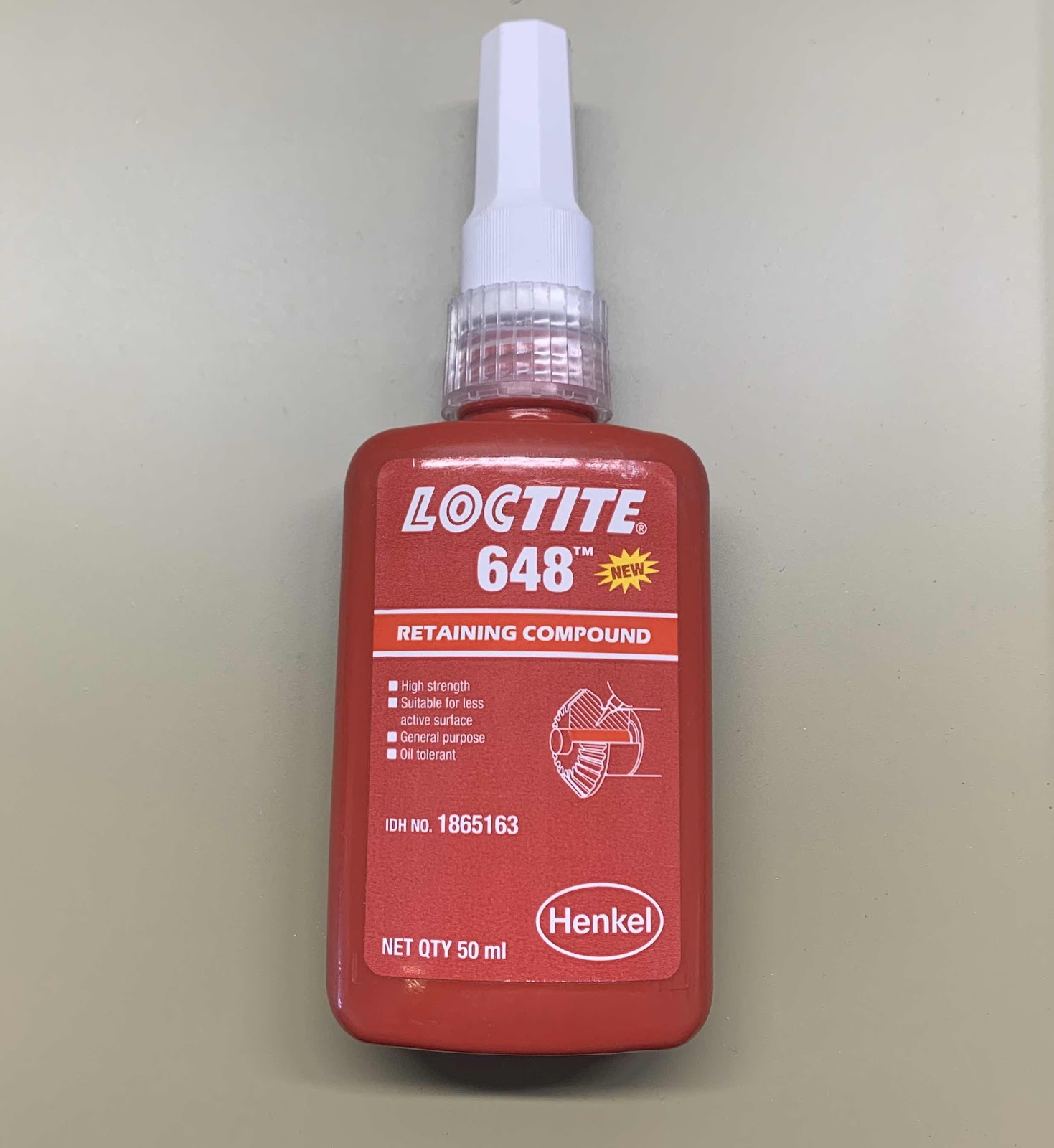
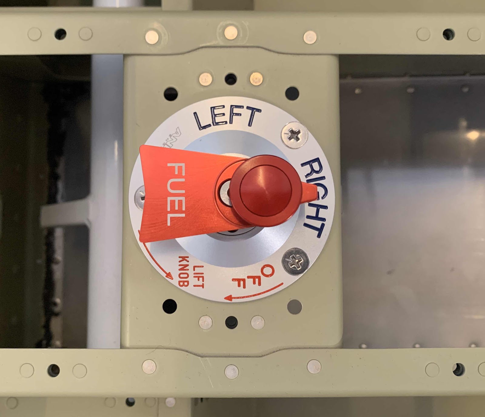
Here is the Fuel Selector right out of the box and it has three “settings”.....Left, Right, and Off.  This Fuel Selector is VERY, VERY NICE!  The tag tied to the mounting hole warns against operating the Selector “dry” with no fuel in the system and to use Loctite 648 on the screws that attach the elbow fittings to the housing.

The first step was to remove the red lever from the Selector.  To do this, you lift up the knob up to expose the attaching screw.  The small angled allen key was supplied in the kit.

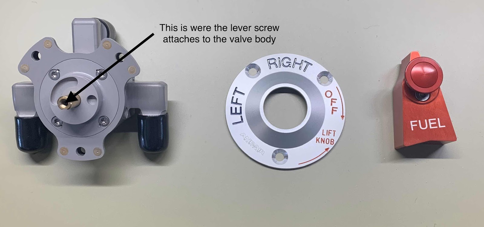
Once the Lever is removed, the pieces look like this....valve body on the left, faceplate in the middle (after I countersunk the three attach holes for MS24693-C273 screws) and Lever on the right.  The little screw that was removed in the step above, screws into the top of the cylinder the arrow is pointing at in the picture.

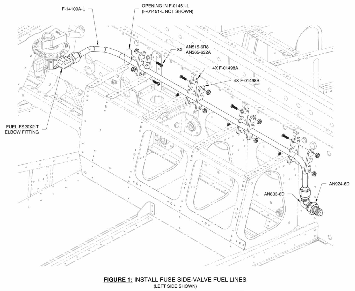
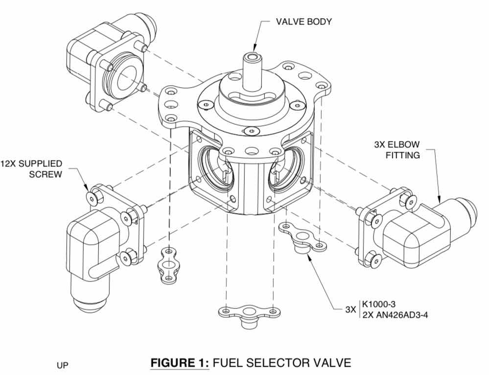
Next, the instructions have you install the elbow fittings to that valve body with the screws supplied from Andair.  Now, if you look at the first picture posted above of the Fuel Selector, the elbow fittings are NOT in the same orientation as in the plans excerpt below.  The elbow fittings pull straight out front the valve body and can be reinserted to the proper orientation (as shown below).

Once the elbow fittings were in the proper orientation, I began to install the supplied screws.  As I mentioned above, Andair says to use Loctite 648 to install the screws.  Here’s the appropriate stuff to use.....

I installed the first screw...


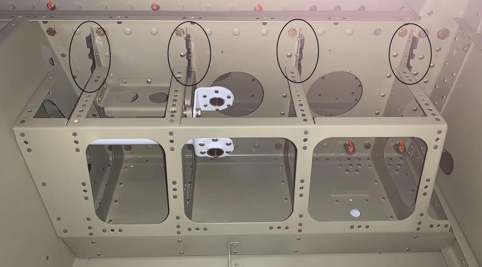
.....and then the other three on this elbow fitting.  Then, installed the other two elbow fittings to the valve body.  Additionally, in the picture above and below, you can see two of the three K1000-3 nutplates riveted to the valve body (circled).


Now, the valve body and the faceplate are attached to the F-14102 Fuel Selector Valve Bracket.....

.....and then the lever is reinstalled.

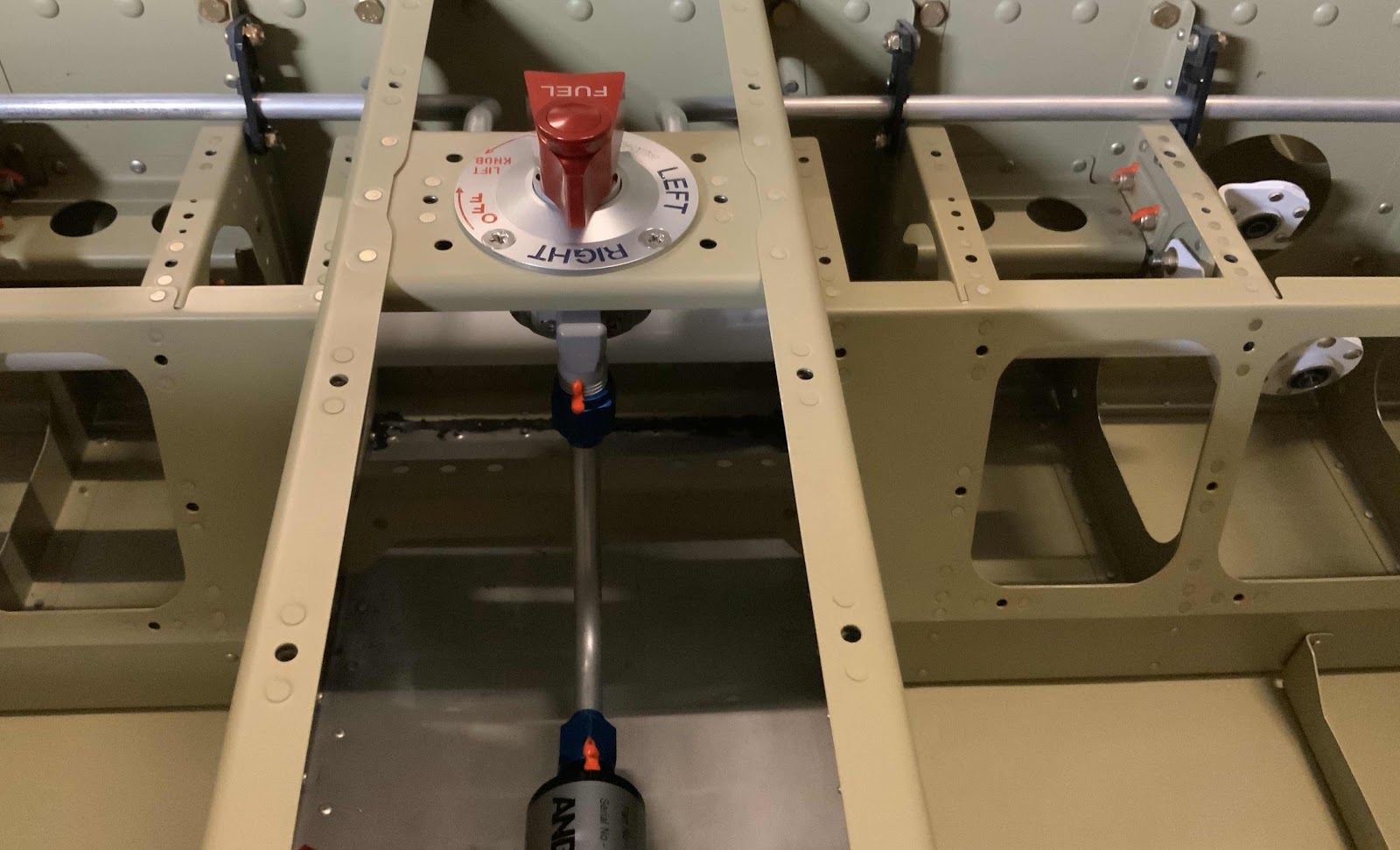
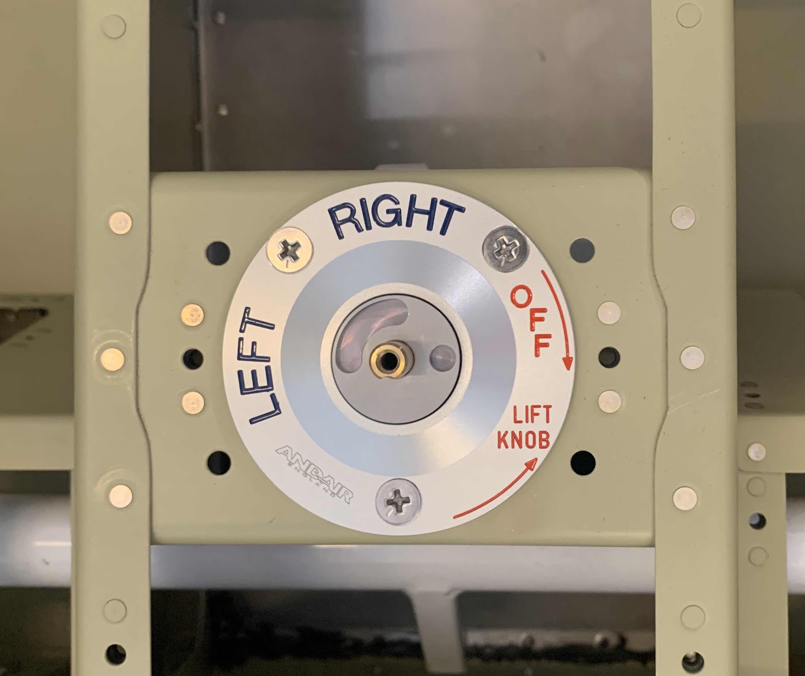
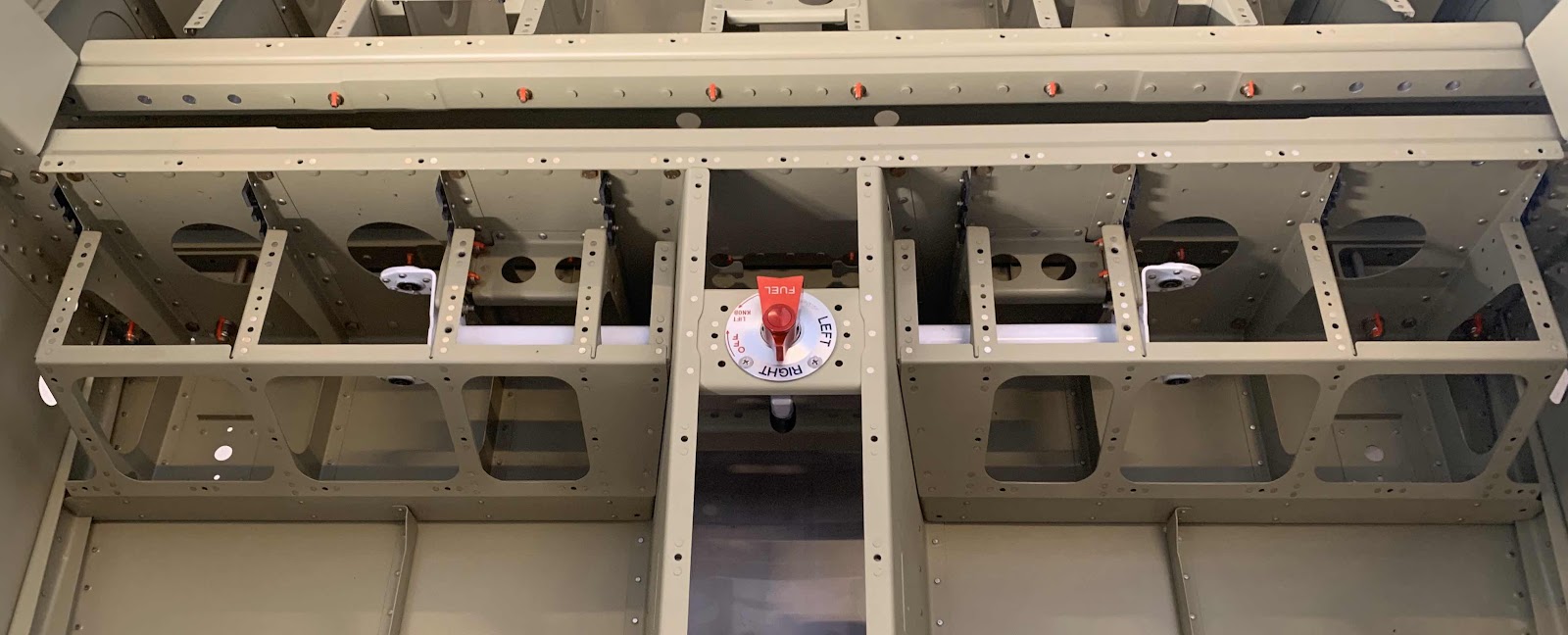
Here is another look at the Fuel Selector from the Firewall looking aft.

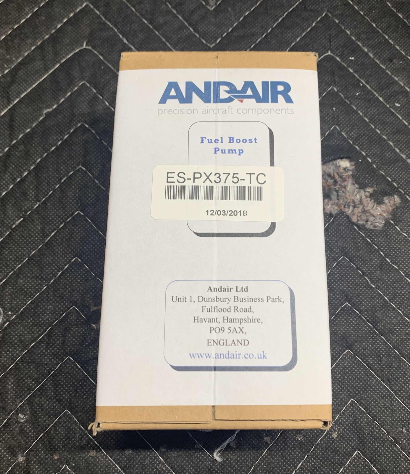
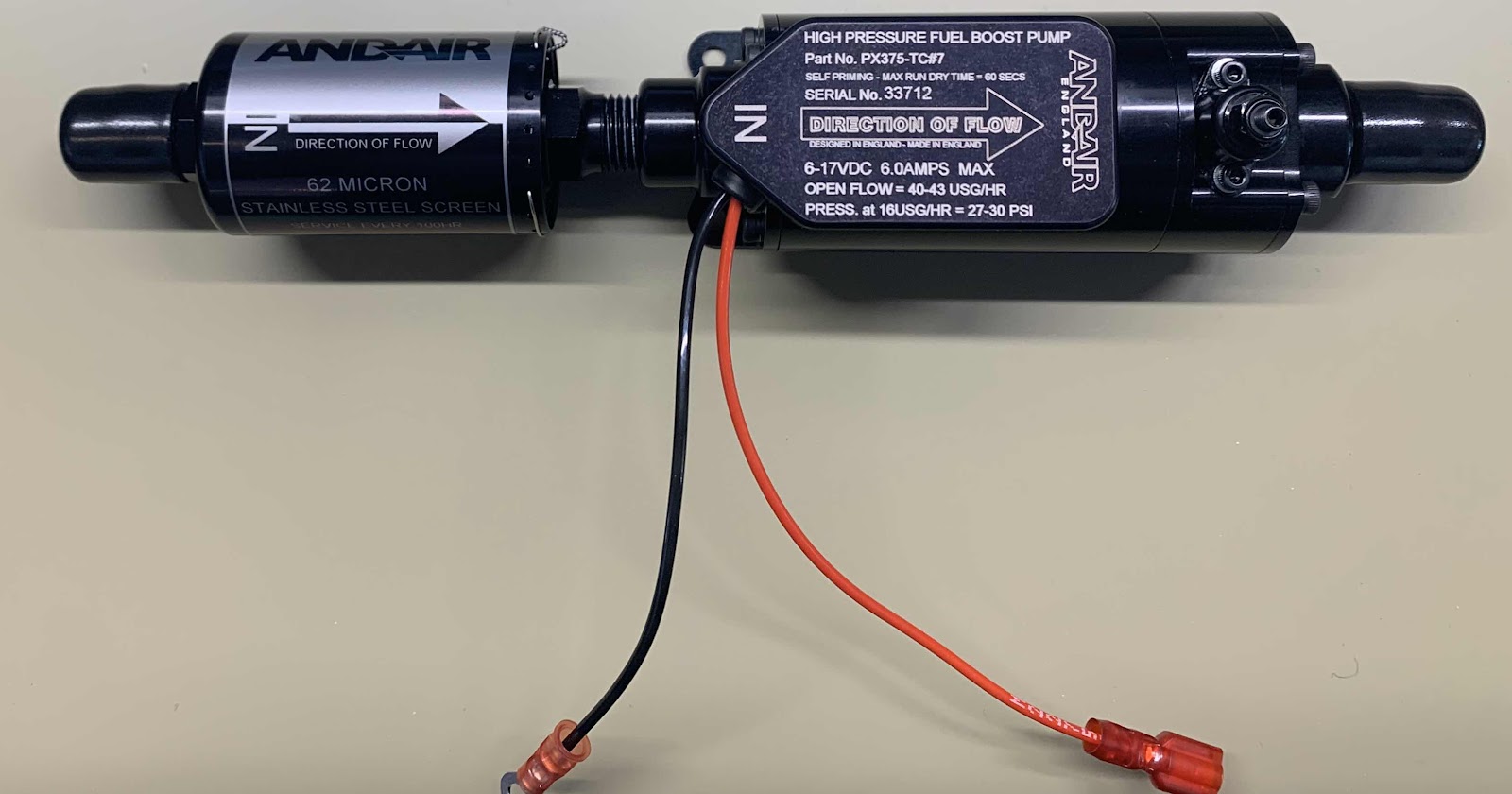
Moving on to the Andair Fuel Boost Pump (Part #ES-PX375-TC).

To begin, an ES-31890 ring terminal (crimped on the black wire) and ES-421-0108 female spade connector (crimped on the red wire) were installed as shown in the excerpt below.  (The actual Fuel Boost Pump will be shown below).

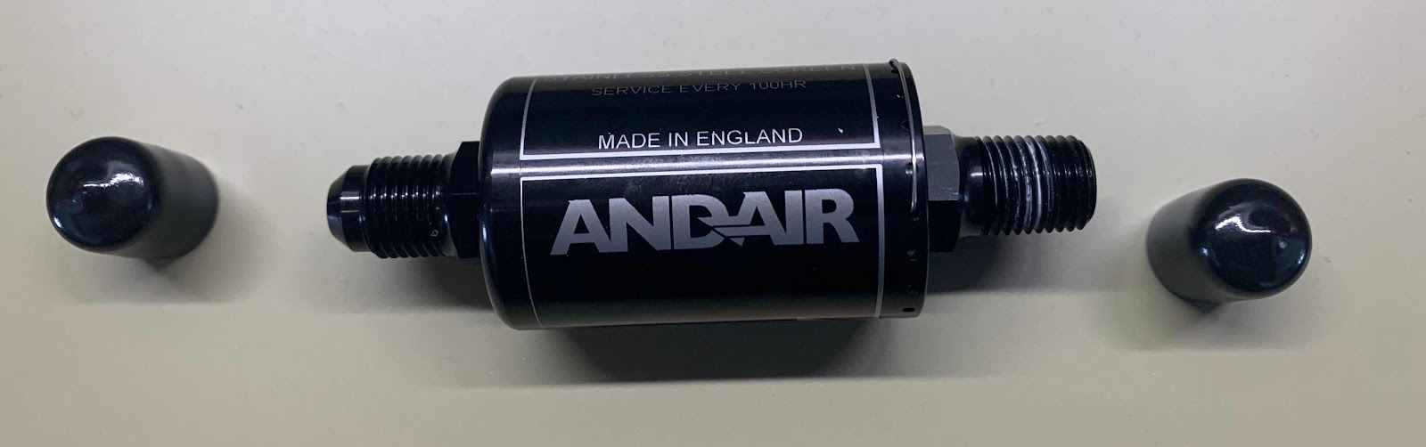
Here is the Andair Fuel Filter (Part #Fuel-FX375-MK)


The Fuel Filter was removed from the box and pipe thread sealant (Permatex thread sealant #59214) was applied to the 1/4 NPT threads.  It was then threaded into the 1/4 NPT end of the Fuel Boost Pump.  Here are the two parts joined together.  Additionally, you can see the ring terminal and spade connector crimped on the red and black wires as prepared above.

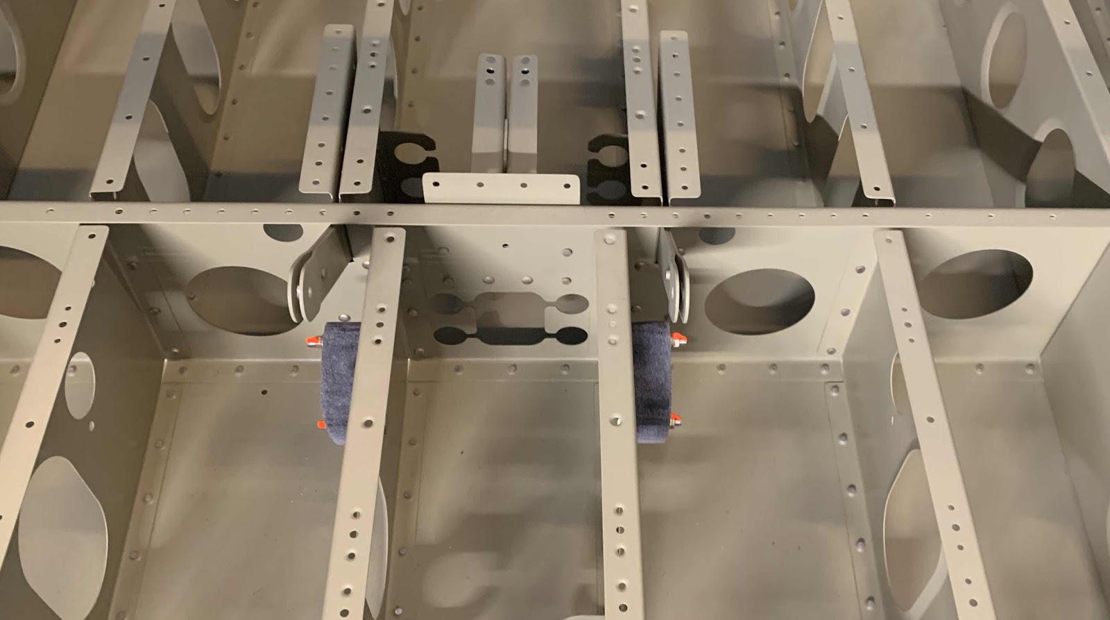
Once the two are joined together, the Fuel Boost Pump is attached to the F-14108A and F-14108B Fuel Pump Brackets with four AN515-8R8 screws.

The ring terminal end of the black wire is attached between the Fuel Pump Bracket and screw head (shown below).

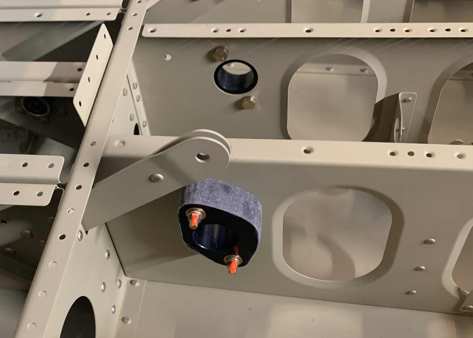
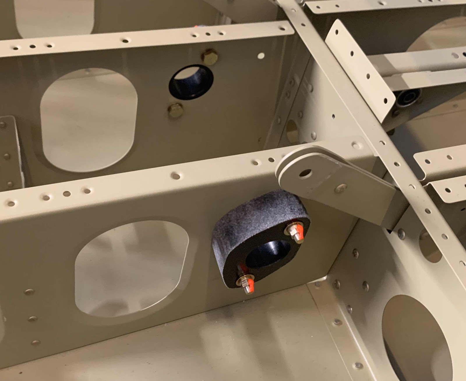
This picture shows the Fuel Selector Valve and Fuel Boost Pump installed on the plane.

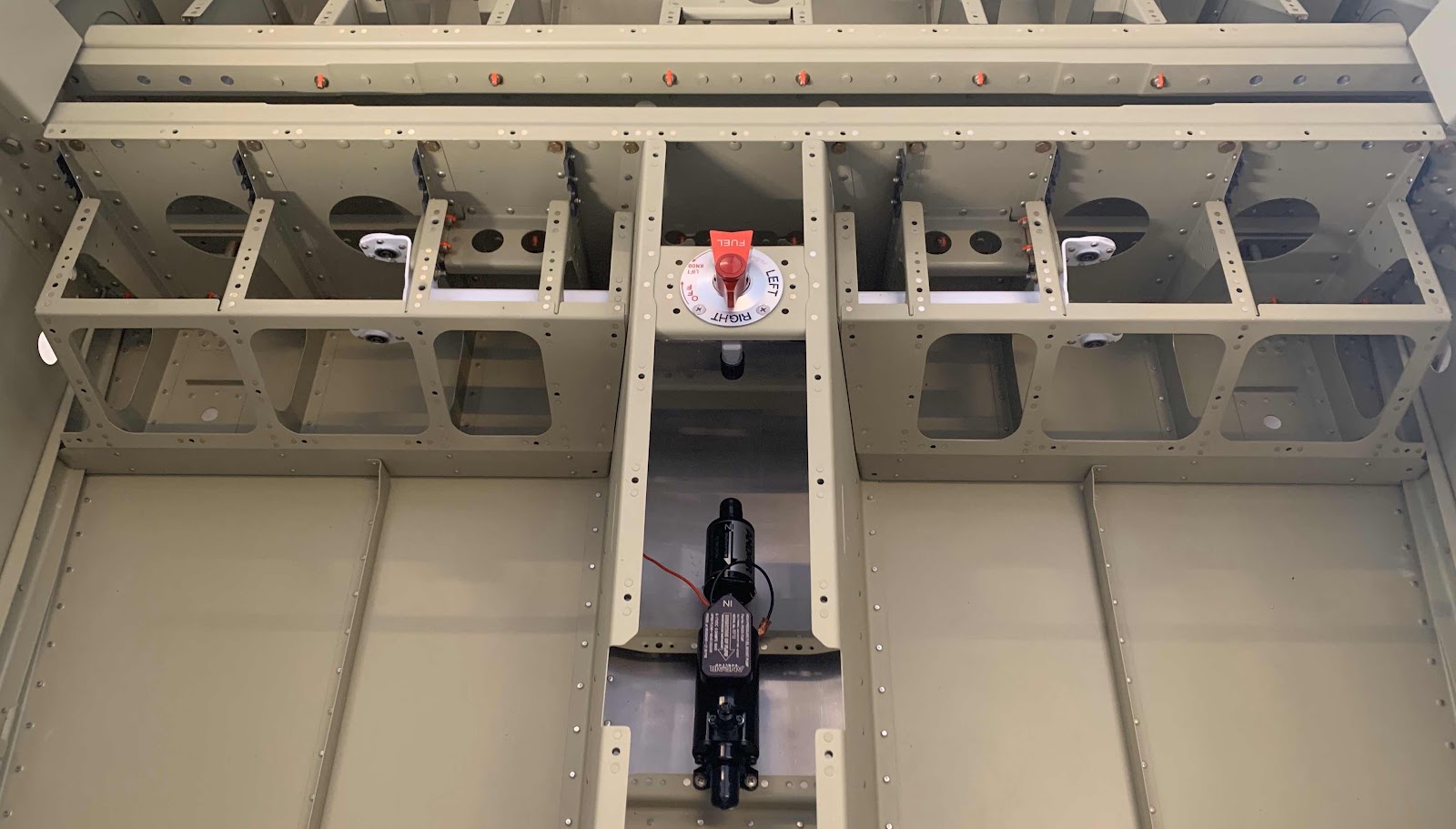
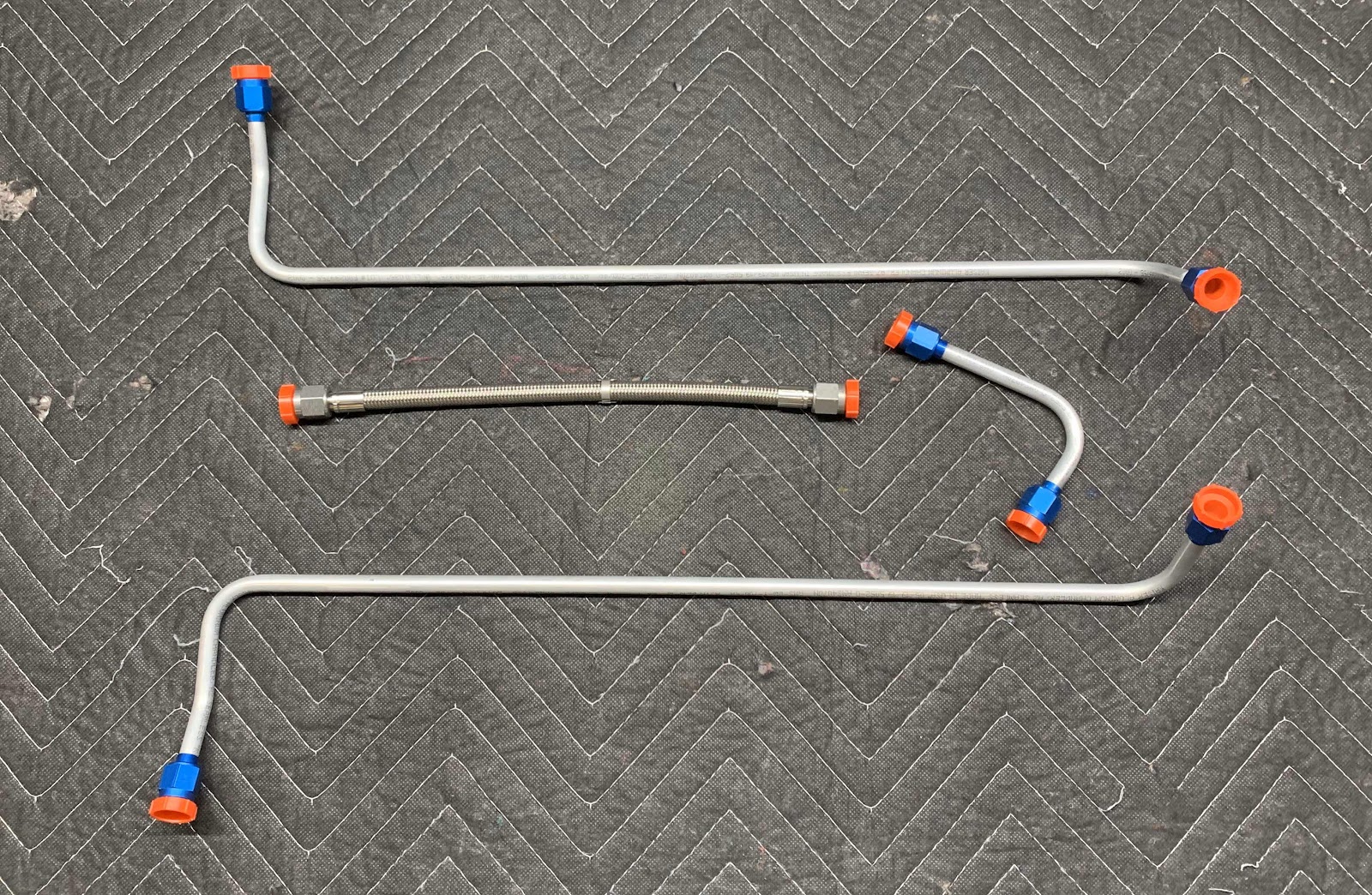
Now, with Part 2 and today’s session completed, the plane is now ready to receive the cabin Fuel Lines.....when they arrive.

Fuselage, Baggage Area (Part 6)

In Part 5, I prepared the two Outboard Bushings.....during today’s session, I completed the two Inboard Bushings.  Here is an excerpt from the plans showing how the two Bushings should be trimmed.....


.....and what mine looked like after being trimmed.  They actually came out pretty close to the template.  I also put them next to each other and sanded all the sides and angles of each piece the same.....just like the Outboard Bushings.

Next, the Bushings were attached to the F-01417-L & -R Seat Ribs as shown in the picture below.

Here is a close up of the -R Bushing (-L is in the background).  The following hardware was used to install each of the Bushings....
- AN3-11A bolts (x2)
- NAS1149F0332P washers (x4)
- MS21042-3 nuts (x2)
As with the Outboard Bushings, the plans stated to NOT torque the bolts/nuts to normal torque values.  So, I got them very snug and “just a little more”.....somewhere in the neighborhood of 25 in/lbs.

Here is a close up of the -L Bushing (-R is in the background).  The same hardware was used to install this Bushing.

That completes the installation of both Outboard and both Inboard Bushings.  These Bushings will be used in a later session for the Flaps actuation.

Saturday, January 18, 2020

Fuselage, Fuel System (Part 2)

In preparation for the Fuel Lines to arrive from Aircraft Speciality, there are a few steps in the plans that need to be completed.  The first step was to separate the eight F-01498 Fuel Line Brackets into parts F-01498A & B as shown in the plans excerpt below.


This is how the parts arrive in the kit from Van’s.  Below, several “sections” have already been removed from the strip.

I initially used a bandsaw to separate each part from the strip and then used 220 grit sandpaper to smooth the edges.  The best way I found to do this was to use sandpaper (with a sticky back) and stick it to my workbench.  Then, slide the parts across the sandpaper.  After being separated and sanded, here are the piles of eight F-01498B’s (left) and eight F-01498A’s (right).

Now, the F-01498A’s need to be installed to the F-01438-L & -R Cover Ribs as shown in the plans excerpt below.


This is the left side Cover Ribs with the “A” Fuel Line Brackets installed.  Each side gets four of these Brackets and are attached with 12 LP4-3 blind rivets.

Here is a close up of the two inboard Brackets (left side).

This is the right side Cover Ribs with the “A” Fuel Line Brackets installed.  These Brackets were also installed with 12 LP4-3 blind rivets.

Here is a close up of the two inboard Brackets (right side).