This blog was created to memorialize the building process of my Van's Aircraft RV-14 and to satisfy the requirements for certification in the Experimental Amateur Built Aircraft category. It will also serve as a central location for ME to reference in the future on processes and techniques I used during the build. Additionally, it will allow my family, friends, and other interested builders the opportunity to follow along during my build…..and might be helpful to someone along the way.
In Parts 17 and 19, I installed/riveted and prosealed the 11 Stiffeners, the Fuel Cap Flange, and the Fuel Drain Flange for the Left Fuel Tank. During this session, I installed/riveted the same pieces, but for the Right Fuel Tank.
In Part 20, I taped off the areas surrounding where the Stiffeners would be riveted. In the picture below, I have removed the tape and all 11 Stiffeners are shown riveted and prosealed into place. Additionally, the Fuel Drain Flange in the lower left corner of the Skin has been riveted and prosealed.
I used the same sized rivets to install the right Fuel Cap Flange as I did on the left. The two sizes of rivets used are AN426AD3-4.5 (x6) and AN426AD3-5 (x4).
Here is the final product with all 10 rivets installed and excess proseal removed.
Well, I’m not doing a very good job of building one Tank at a time.....so, I’m going to stop saying it. Instead, I’ll say.....I’m building the Tanks together. Prior to applying the Proseal, I have to scuff the mating surfaces of the Right Tank Skin (just like for the Left). If you look closely in the two pictures below, you can see the scuffed “lines” (along each row of holes). Each row of holes will be used to attach the Stiffeners and the Ribs.
In the first picture, you can also see the area on the bottom left where the Fuel Drain Flange will be installed. And in the second picture, you can see the area on the bottom left where the Fuel Cap Flange will be installed.
Once all the required areas were properly scuffed, I inserted all 88 AN426AD3-3.5 rivets into the holes for the 11 Stiffeners and taped them into place. I will be back-riveting these rivets when I install the Stiffeners.
Lastly, I taped off the areas where the Stiffeners will be riveted into place to help reduce any mess while using the Proseal. The Right Tank Skin has been prepared and is now ready to have the Stiffeners riveted into place and Proseal applied.
Today’s session was spent working on the Left T-00007B Fuel Cap Flange and T-00005B-L Vent Line Clip. I’ve circled them in the plans excerpt below.
The plans called for the bottom three holes to receive AN426AD3-4.5 rivets and the remaining seven holes to receive AN426AD3-5 rivets. Of those seven rivets, I felt the 3-5 rivets would be to long and I was worried about “tipping” the rivet when I set it. So, I also used 3-4.5 rivets is the top three holes as well. The photo below shows the lengths of each of the rivets I used to install the Fuel Cap Flange. (I will also use the same lengths on the Right Fuel Tank).
Here is what the backside (or inside the Fuel Tank) looks like prior to setting the 10 rivets. In this picture, you can see the Vent Line Clip on the bottom most rivet. I doubled checked the proper orientation for this Clip at least 10 times.
Using an acid brush, I applied Proseal to the Flange and to the Tank Skin, set it in place, and back riveted the 10 rivets. Once that was complete, I applied Proseal to the backside of the Flange as shown below. I know, I got a little excited with the Proseal, but I DO NOT want the Tanks to leak.
I used MEK to clean up the Proseal from the top of the Tank Skin.....here is what it looks like. I think it turned out great!
OK. I know I said I was going to concentrate on one Tank at a time.....starting with the Left. Well, I still am....except for today. Since I already installed, riveted, and Prosealed the two Fuel Flanges and Anti-Rotation Plate on the Left Tank Inboard Rib-AFT.....thought I would do the same for the Right.....so I did!
Here is the interior side of the Right Tank Inboard Rib-AFT showing the two Fuel Flanges and the Anti-Rotation Plate.
And here is the back. I used an acid brush to apply the Proseal on both sides and a rag dipped in MEK to remove the excess.
This didn’t take long and now it’s finished for when I start on the Right Tank.
Moving on in the plans to the installation of the T-00004 Tanks Stiffeners (x10), T-00005A Tank Stiffener (x1), and the VA-112 Drain Flange. In a effort to try and reduce the mess, I taped off the area where the the Stiffeners will be installed. I also put tape on the area where the Ribs will run between the Stiffeners to prevent Proseal from getting in the way of the Ribs installation. Here is what it looked like after I taped it off.
And here is what it looks like after having the rivets and Proseal installed.....and tape removed. You can see the 11 Stiffeners and the Drain Valve (bottom right corner). I back-riveted all the rivets in the Stiffeners and used the squeezer for the Drain Valve (which I guess I could have back-riveted also).
Next, I installed the forward row of Stiffeners shown below.
And this is just a close up of a few of the Stiffeners and Drain Flange.
This is the “underside” of the Tank showing the two row of rivets that were installed I the Stiffeners. All the rivets turned out flush and the result looks very good.
“The T-1003C-L & -R Tank Inboard Ribs-FWD, T-1003B-R & -L Tank Inboard Ribs-AFT, and T-1003-L & -R Tank Outboard Ribs each have two .188 diameter holes. These holes are used to hold the ribs in proper alignment with the tool during hydropress forming of the ribs. Install AN470AD6-5 rivets in the .188 rib holes. Use a C-Frame tool and a heavy hammer to set the rivets only enough for them to be retained in the tooling holes.”
As I was accomplishing this step, I decided the 6-5 rivets were too long and would not look very good installed. So, I used a rivet cutter to shorten the length of the rivets. You can’t really tell in the picture below, but the three rivets in the middle have been cut to a shorter length (the original length rivets are on either side). I also don’t have a C-Frame, so I used a 3x rivet gun (with a #6 set) and the flat part of the bench vice (as the bucking bar) to shoot the rivets. I was very pleased with the final results. Below are the Left and Right Tank Inboard Ribs-FWD showing the manufactured heads on the right and the shopheads on the left.
Below is the Left and Right Tank Inboard Ribs-AFT with the rivets installed.
And lastly, here is the Left and Right Tank Outboard Ribs with rivets installed.
After all the rivets were set, I applied Proseal to each of them (10 total). Below is the Tank Inboard Ribs-FWD and AFT with the Proseal applied. The FWD Ribs were cleaned up with MEK and the finished product doesn’t look as messy. I also applied the Proseal the Outboard Ribs (forgot to take a picture).
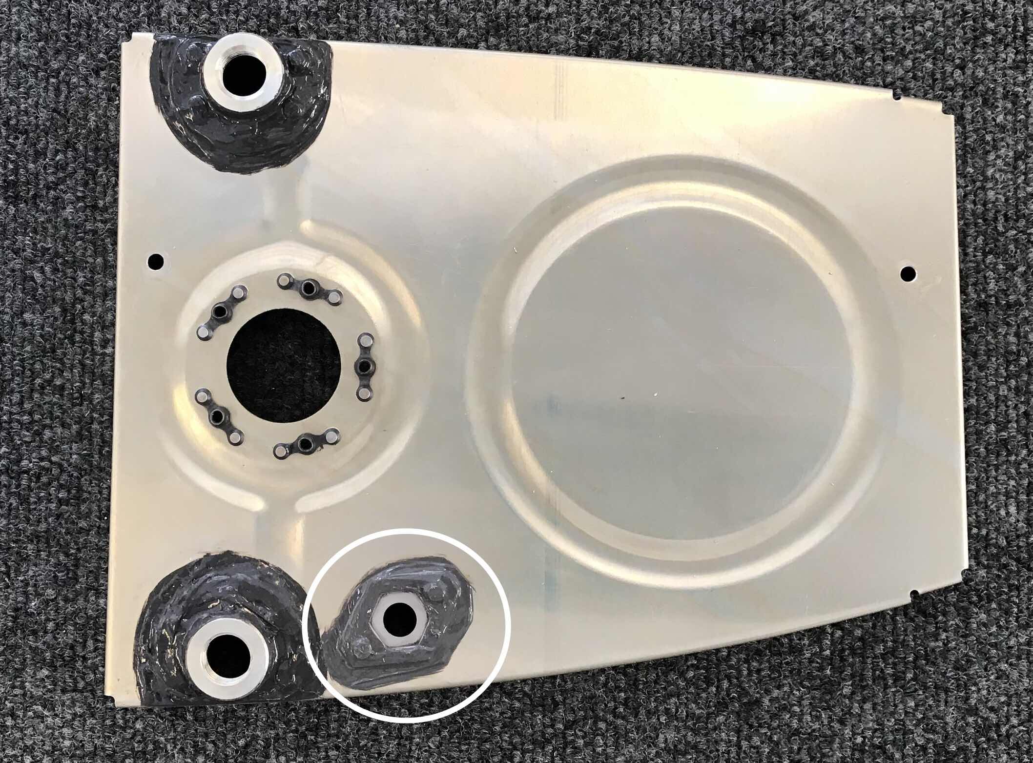
The next piece to get installed is the T-1010 Anti-Rotation Plate (shown in the circle below). This piece is held on by two AN470AD4-5 rivets and will be used in the next few steps with Fuel Tank Vent Line.
Once the Anti-Rotation Plate was installed and Prosealed, the T-00004 Tanks Stiffeners (x 11), T-00005A Tank Stiffener (x 1), and the VA-112 Drain Flange (x 1) get installed.
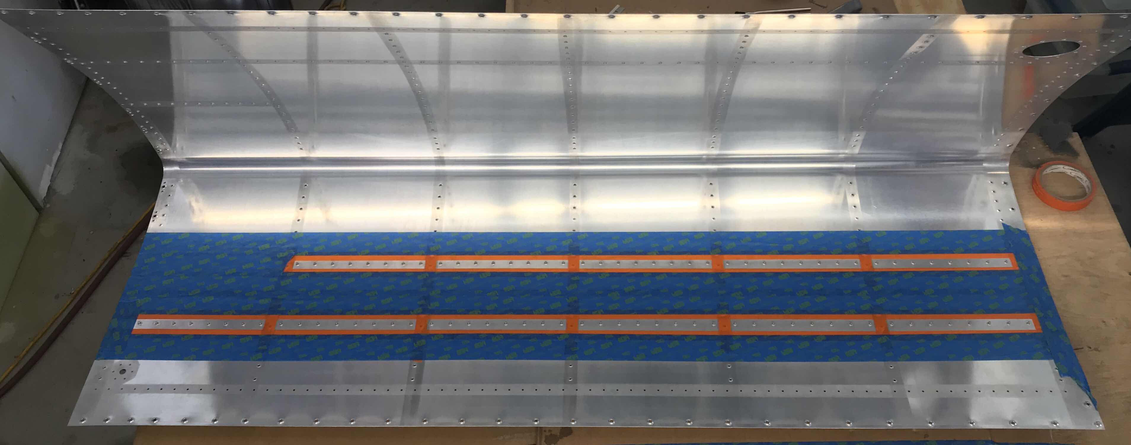
However, prior to their installation, I need to scuff the mating areas on the Tank Skins. To do this, I marked off approximately 1/2 on either side of the row of dimpled holes. If you look closely at the picture below, you can see the “lines” that were scuffed using a grey Scothbrite pad. I will repeat the same process on the upper portion of the Tank Skin tomorrow.
As I mentioned above, the 11 Tank Stiffeners get installed next. The 11 Stiffeners will be installed between the orange tape lines in the picture below. I’m hoping by using the tape, it will help reduce some the clean up after the installation. (At least I might have pretty lines)
Tomorrow, I will start installing the Stiffeners onto the Tank Skins.
Up until this point, I have been preparing the Left and Right Fuel Tanks together at the same time. Now that it’s time to put pieces together using Proseal, I have decided to assemble the Tanks one at a time. I think I would feel better (and hopefully get a better result) if I just assemble one Tank from start to finish. Since the Left side parts, assemblies, and installations are used in the plans, it makes sense to start with the Left Tank.
HERE WE GO!!!!!
I’m using the Flamemaster brand that seems to be popular and common among builders. However, I used a local vendor and did not purchase mine through Van’s. Part A is in the yellow can (sealing compound) and Part B is in the smaller container on top (accelerator). The two parts are mixed at a ratio of 10:1. The tubes come with the proper mix ratio already figured out. The user just has to mix the compound and accelerator (in the container). Once that is complete, you can use the tubs like caulking. Very easy and no clean up.
Here are my supplies......popsicle sticks, acid brushes, LOTS of gloves (I have boxes of them), a scale, and an aluminum mixing plate.
Below is my very first attempt at using Proseal.....ever! I suspect this might be a little heavy on the application, but I don’t want any leaks. This is the internal side of the T-1003B-L Tank Inboard Rib. To attach the two VA-141 Fuel Flanges, I first used an acid brush to apply Proseal on the underside of the Flanges and on the Rib itself. I then pressed the Flanges into position, clecoed the corresponding holes, and used my pneumatic squeezer to wet set the 10 AN470AD4-5. After the rivets were set, I used the same acid brush to coat the shophead side of the rivets with Proseal.
Here is the opposite side of the Rib showing the Proseal on the manufactured heads of the rivets.
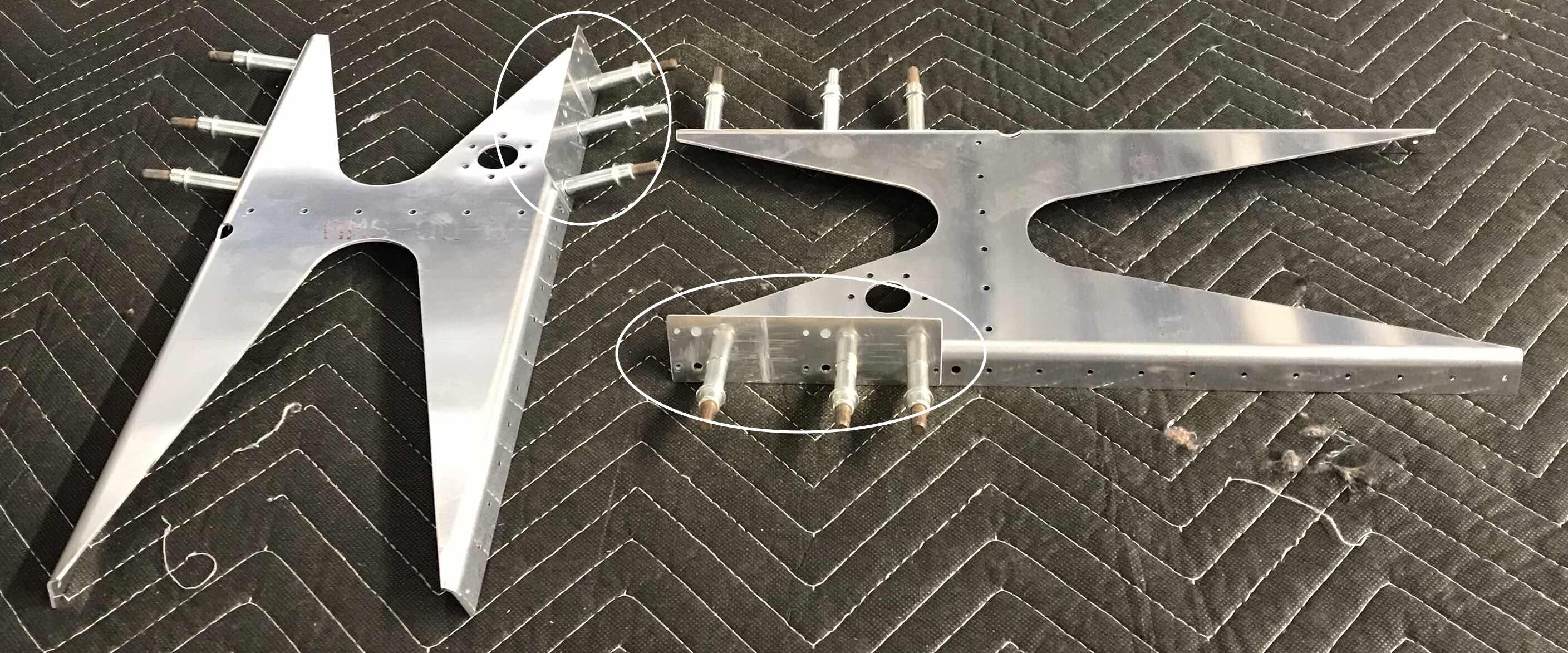
I’m almost ready to start with Proseal!! However, prior to doing that I need to rivet together a few pieces that are outside the Tanks. The picture below shows the 11 pieces (outside the Tank) that need to be riveted together for the Left Fuel Tank.
Below shows the same 11 pieces (also outside the Tank) that need to be riveted together for the Right Fuel Tank.
And here are the two Tank Attach Brackets with all the parts and pieces riveted together.
Next, I riveted the five K1000-08D nutplates to each Fuel Tank Inboard Rib-Aft. The plans indicate NO SEALANT is required for the installation of these nutplates.
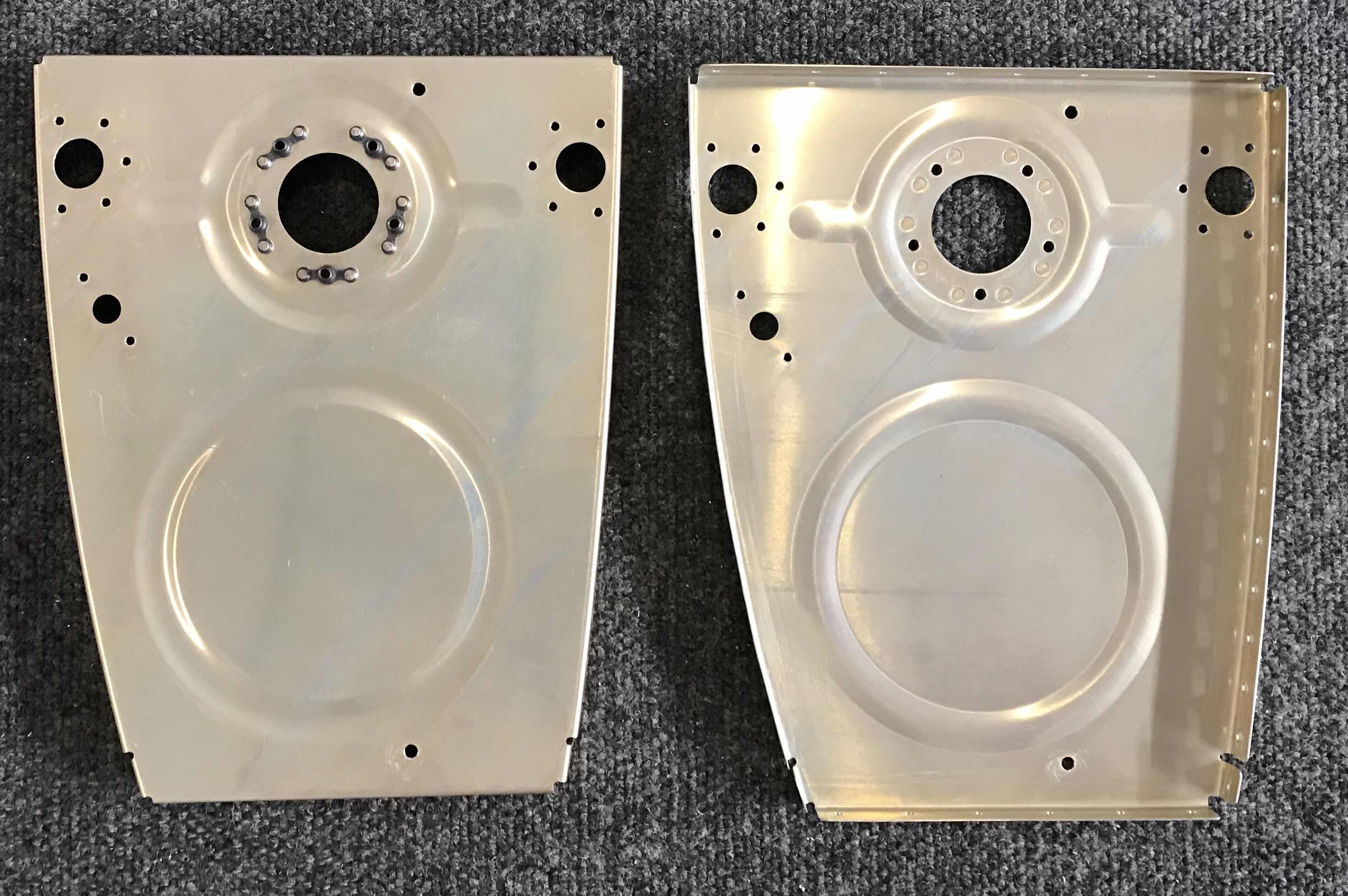
The Left Inboard Rib shows the shophead side of the rivets with the nutplates installed (internal part of the tank) and the Right Inboard Rib shows the manufactured heads of the rivets (external part of the tank).
Alright, I’m to a point in the Tanks build where pieces need to be riveted together. So, before that, I want to prime a few of the external Fuel Tank parts. The plans specifically state:
“If desired, prime the T-1005B and T-1005C Shims, T-1012 Tank Attach Zees, and the external portion of the T-00006-L & -R Tank Attach Brackets”
In Part 3, I prepared and Akzo primed the Tank Attach Zees. So, I’ll need to Akzo prime the Shims and the Attach Brackets. Below are the Tank Attach Brackets taped off for primer.....
.....and here are the same Brackets after being primed.....
.....and after the tape has been removed.
Below are the four Shims (two for each Tank) and the VA-146 Flange Bearings (one for each Tank) prior to being primed.
And the same pieces after.
That’s all for today’s session. I will start assembly and riveting tomorrow.
As I mentioned in several posts, I will be treating all the Fuel Tank parts (inside and outside) with Alumiprep and Alodine. I completed the bulk of this process in Part 10, but still have the Fuel Tank Skins, Rear Baffles, and long J-Stiffeners.
Since they are such big pieces, I obviously wasn’t able to “dip” them like all the other parts. So, I used spray bottles to apply the Alumiprep and Alodine. In the picture below, the six pieces have been treated and are hanging up to dry.
This session was actually completed yesterday, Saturday. However, I wasn’t fast enough to get the entry submitted before midnight. So......
As I’ve mentioned in a couple of my posts, I will not PRIME the inside of the Fuel Tanks. Many builders don’t recommend it and neither does Van’s. However, I will Aluiprep and Alodine the parts and pieces that make up the tank (including the internal pieces). I’ve shown my setup before, but here is how I treat most of the parts and pieces. They get submerged in the Alumiprep (far right), distilled water rinse (middle), submerged in Alodine (far left), distilled water rinse, and hung up to dry on the clothesline. I’ve found this process to be easy and quick. you can see one of the interior tanks ribs in the Alumiprep and one in the Alodine.
As I’ve used several times times in the past, I will use my “clothesline” technique for drying all the parts and pieces. It is safety wire run between two old department store clothes racks. The blue painters tape are labels for each specific rib (left or right Tank, 1 - 6).....left side of the rack for Left Fuel Tank and right side for the Right Fuel Tank.
Here is the same picture, but with all the parts hanging up to dry. With the exception of the Fuel Tank Skins, the long T-00003 Tank J-Stiffener, and the Tank Attach Zees, all the parts that make up both Fuel Tanks are hanging here.
The #40 holes in the T-00006-L & -R Tank Attach Brackets had to be countersunk to accept the dimples in the Fuel Tank Skins or the T-1005B and T-1005C Shims (depending on the location of the holes). Because the Flanges of the Brackets are not 90% and at a slight angle, it was difficult to make the countersinks with the Bracket “square”. So, as shown below, I clamped several scrap pieces of 2x6 and 2x4 to my work bench. This created the proper height for the Flange to rest “squarely” on the wood. This made a very solid and stable platform to make the countersinks.
Here are the two Tank Attach Brackets after the #40 holes were countersunk. To get the proper depth on the countersinks, I dimpled a piece of scrap .032 aluminum and used it as a gauge.....worked pretty well I think.
Lastly during his session, I deburred all the holes and cleaned the edges of the two Rear Tank Baffles.
During the last session, I started the dimpling process on the Left Tank Skin. I used my pneumatic squeezer to dimple all the #8 screw hole locations and the #40 holes I could reach with the 3” yoke. To start today’s session, I dimpled the remaining #40 holes with the DRDT-2. In the picture below, you can see the Left Tank Skin and the DRDT-2 machine getting ready to work.
The picture below shows the completed Left Tank Skin with all the required dimples.
After completing the Left Tank Skin, I moved on to the Right. Initially, I had to clean the edges, make the lap joints on both training edges, and use the pneumatic squeezer to dimple all the #8 screw hole locations. Once that was completed, I used the DRDT-2 to dimple the remaining #40 holes. Shown below is the completed Right Tank Skin.
As I mentioned before, I will NOT be priming the inside of the Fuel Tanks; however, I will treat them with Alumiprep and Alodine. Both Tank Skins are now ready for that treatment.
The next step in the process is preparing the T-00007B Fuel Cap Flanges. In the picture below, the Fuel Cap Flanges are the red rings and the the Fuel Caps are grey. They were provided by Van’s in the packaging shown. This step required the 10 #40 holes in each Flange be machine countersunk to accept the dimples in the Fuel Tank Skins.
In order to keep the Flanges flat and stable for countersinking, I used three small pieces of 2x4 that I previously cut when making the Wing cradles.. The portion of the Flange that accepts the cap sticks down (into the Fuel Tank once installed) and doesn’t allow the cap to remain flat (rocks to the side). So, the use of the 2x4’s solved that problem.
After many test fits, the completed Flanges are shown below with their respective Fuel Caps. You can see the shiny countersinks in each of the Flanges.
This is a view with the one of the Fuel Cap Flange clecoed into place on the Right Fuel Tank Skin. This is the opening in the Fuel Tanks that will be used to fill the tanks with 100LL avgas (until an alternative fuel is approved by the FAA).
Next, the T-1005BC Shims had to be separated, trimmed, and deburred. Here is the raw product provided from Van’s.....
.....and here are the four Shims separated and with clean edges.
Once separated, they were clecoed into place on the T-00006-L Tank Attach Bracket. Circled in the picture below are the two T-1005B Shims.....
.....and circled below are the two T-1005C Shims clecoed to the Tank Attach Bracket.
I feel like lots of progress was made during this session. I will continue working from here tomorrow.