Tuesday, October 29, 2019

Fuselage, FWD/MID Side Structure (Part 24)

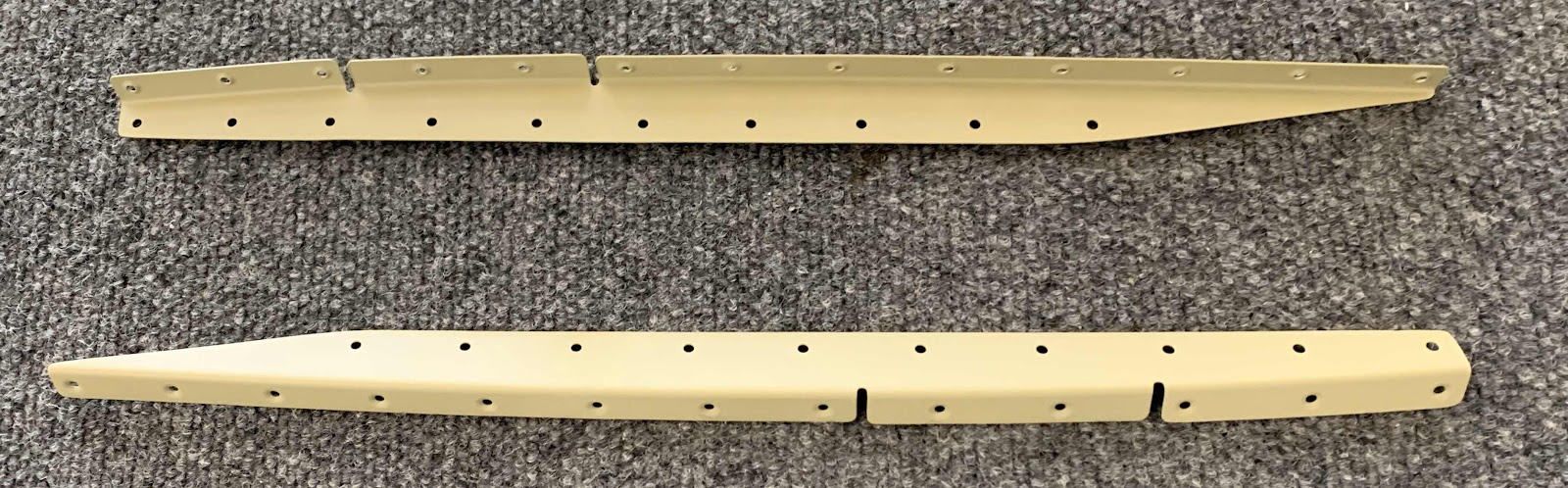
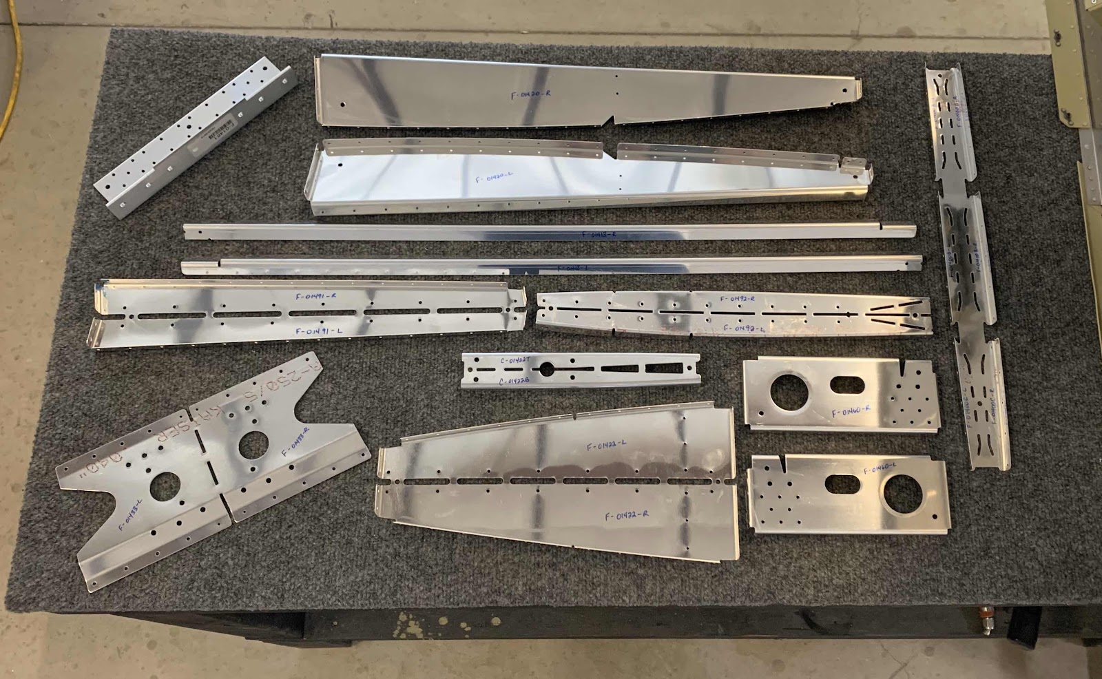
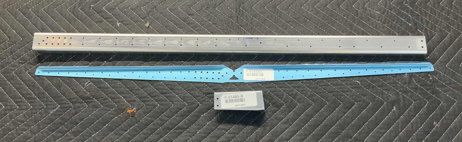
In Part X, I talked about messing up the forward holes on the Right Lower Longeron Assembly.  As I discussed, instead of coming up with a fix, I decided to order new parts and make it right.  These are the three new parts that I needed to rebuild the Longeron Assembly.....

- F-01444-R:  Longeron, FWD Fuselage
- F-01444A:  Doubler, Longeron
- F-01489-R:  Bracket Lower Engine Mount

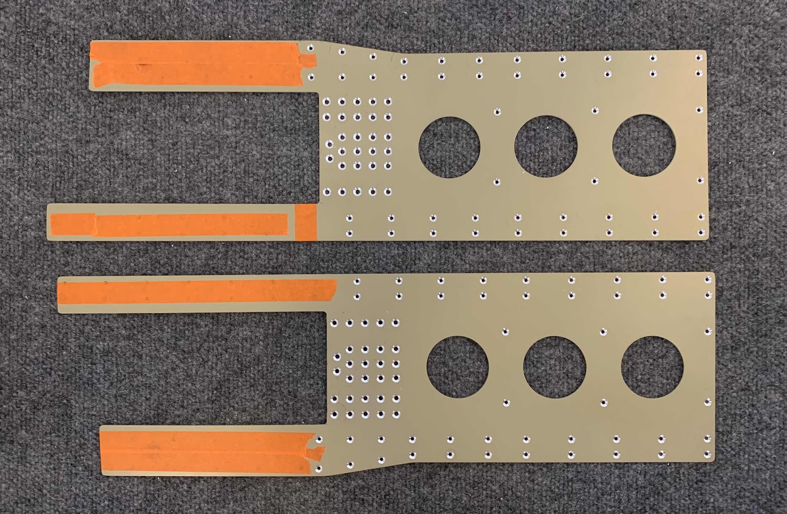
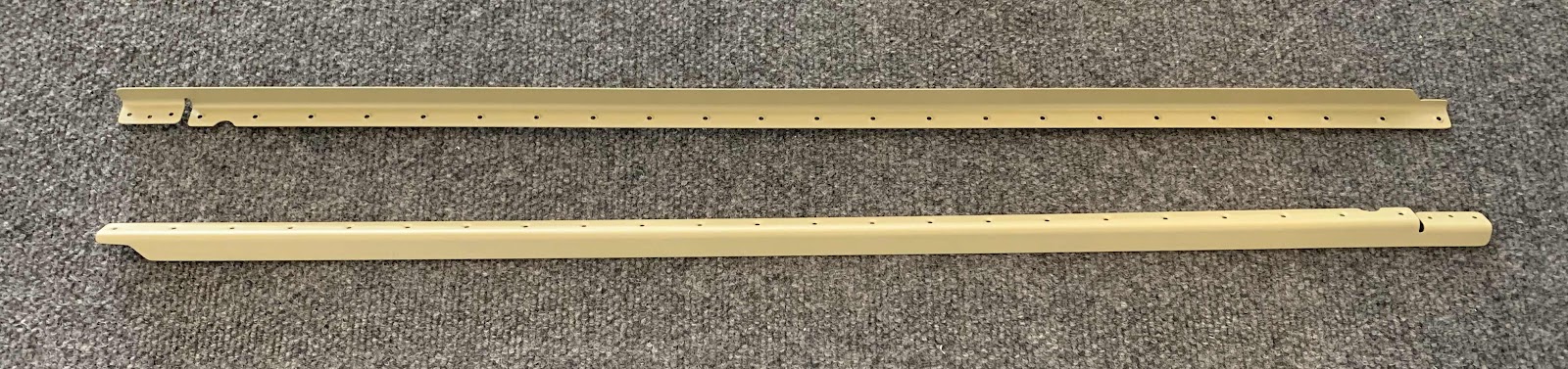
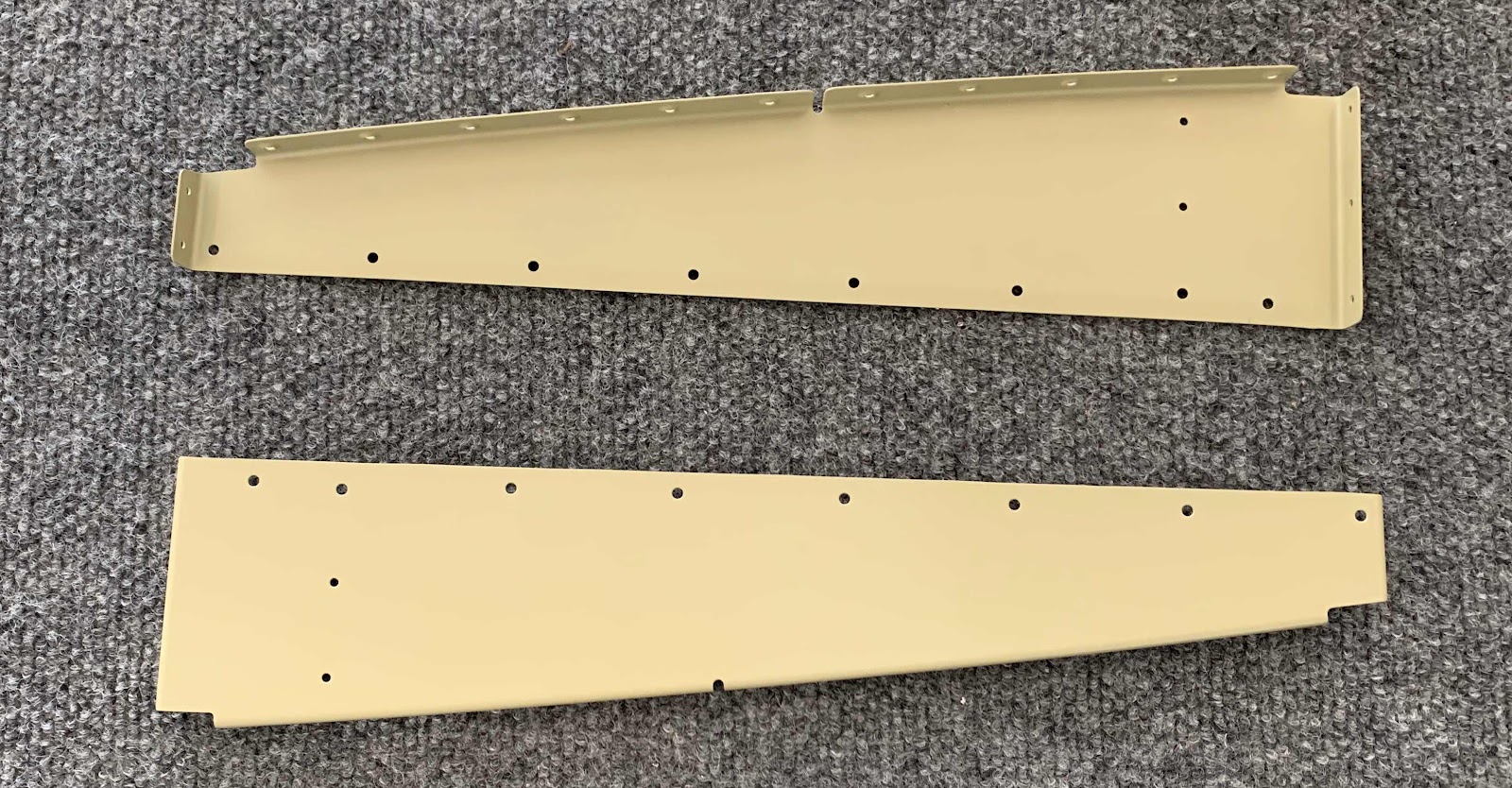
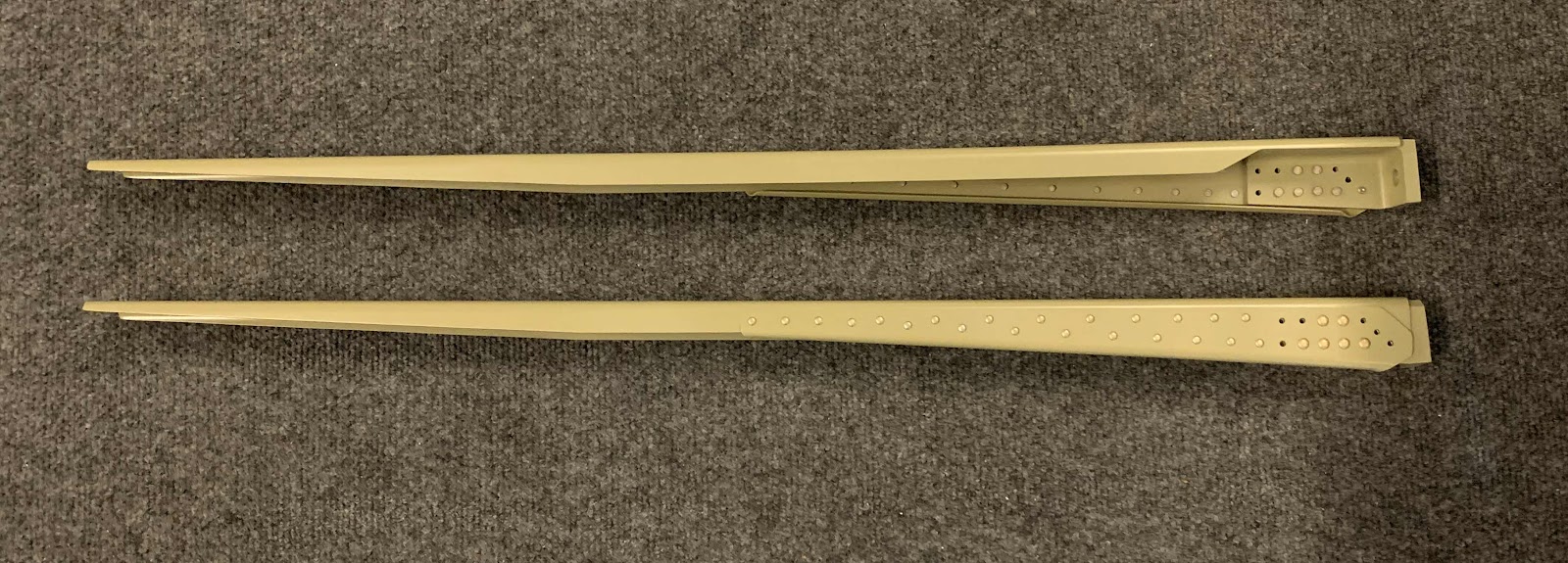
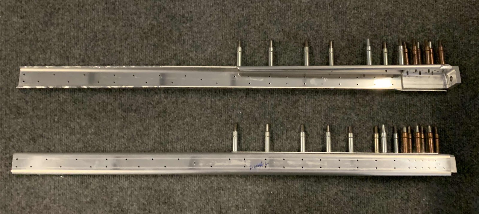
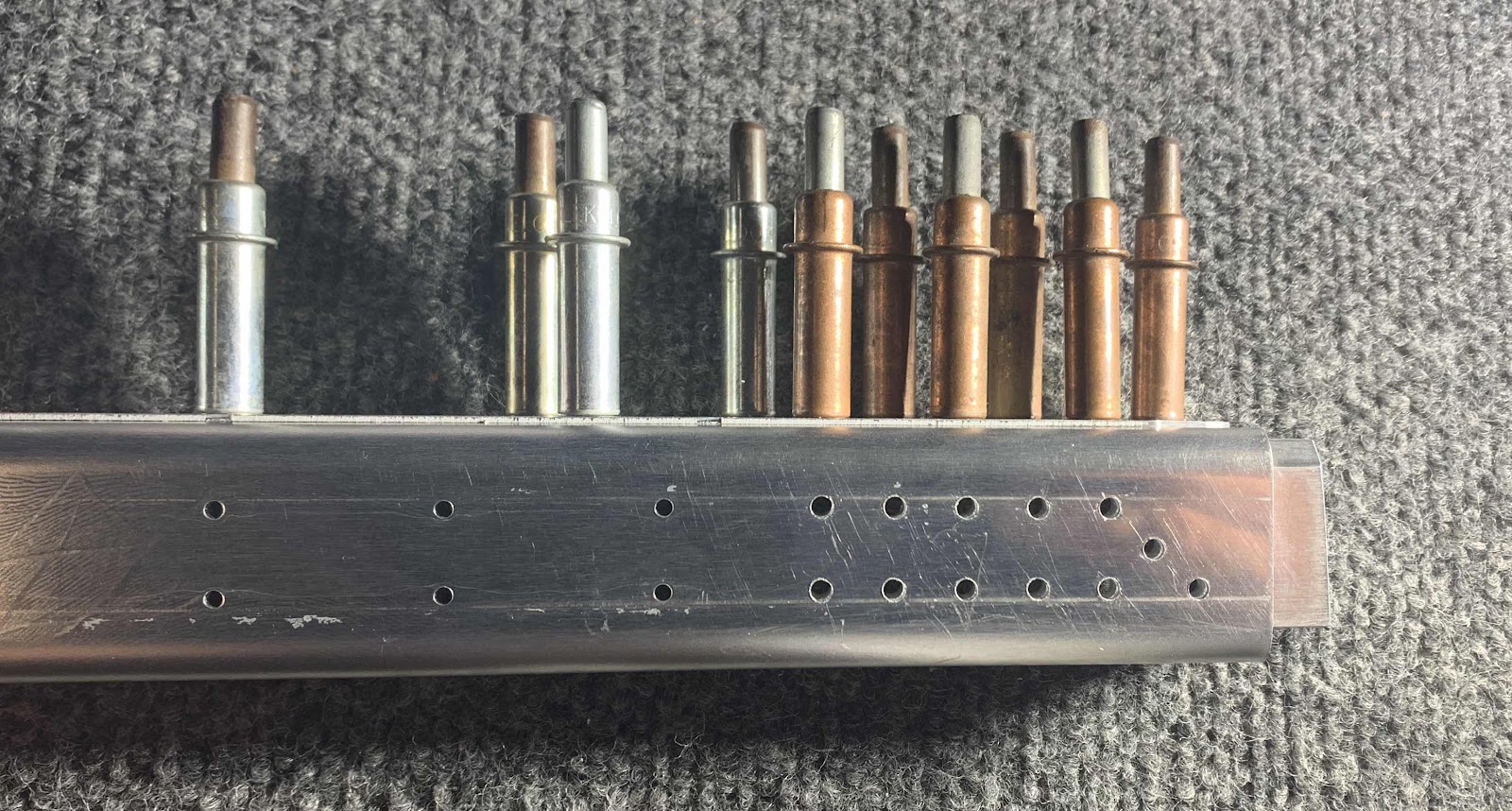
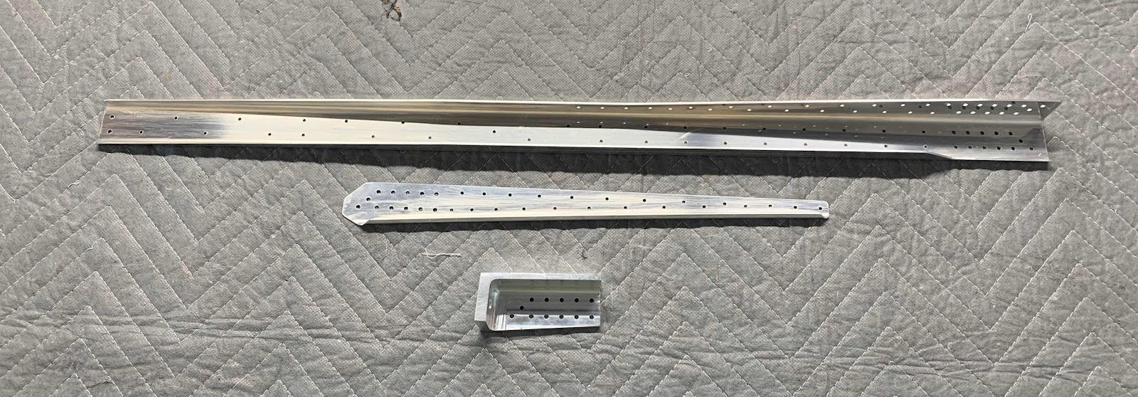
Here are the pieces after all the prep work was completed.

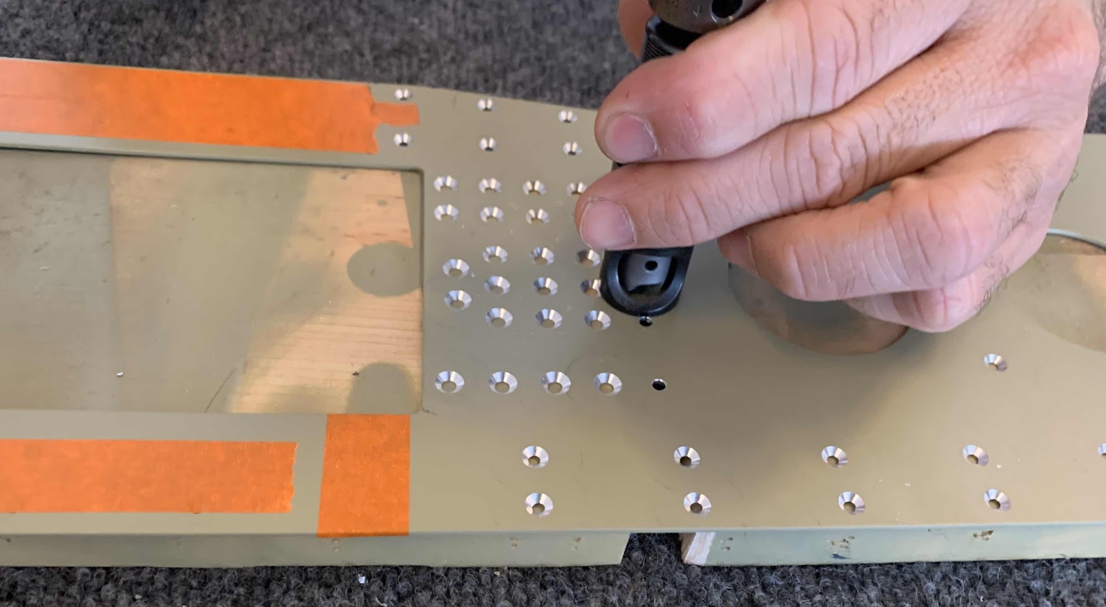
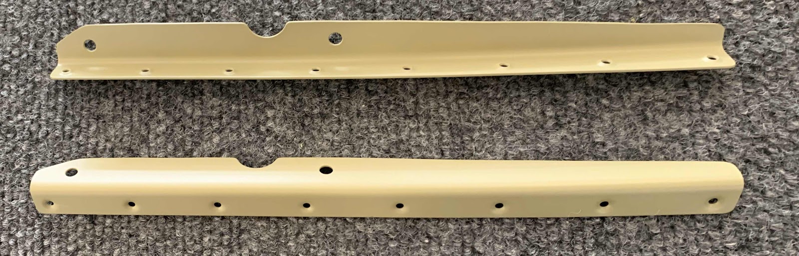
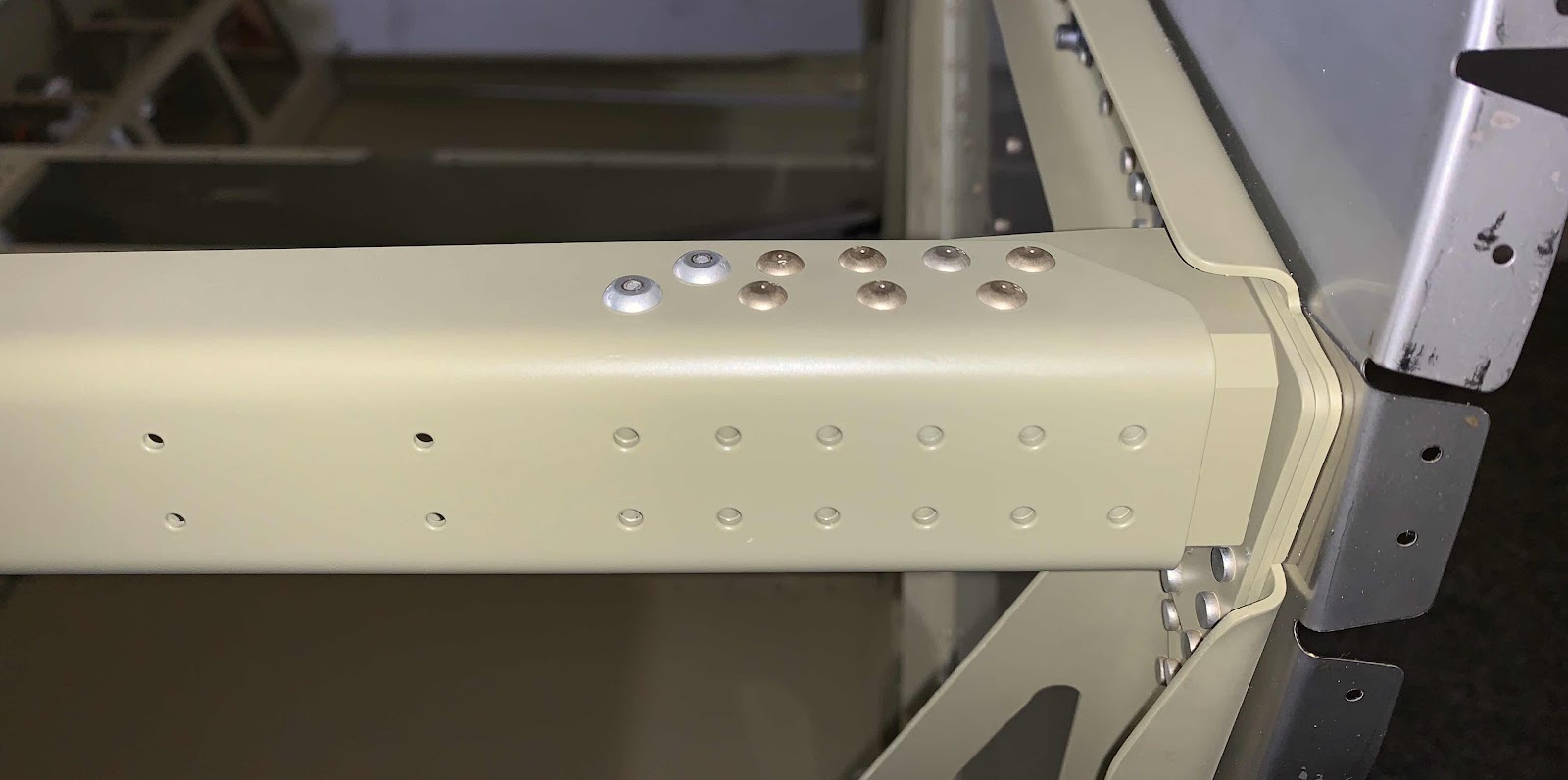
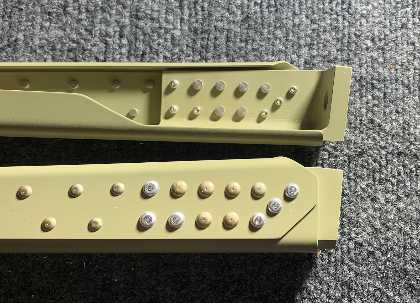
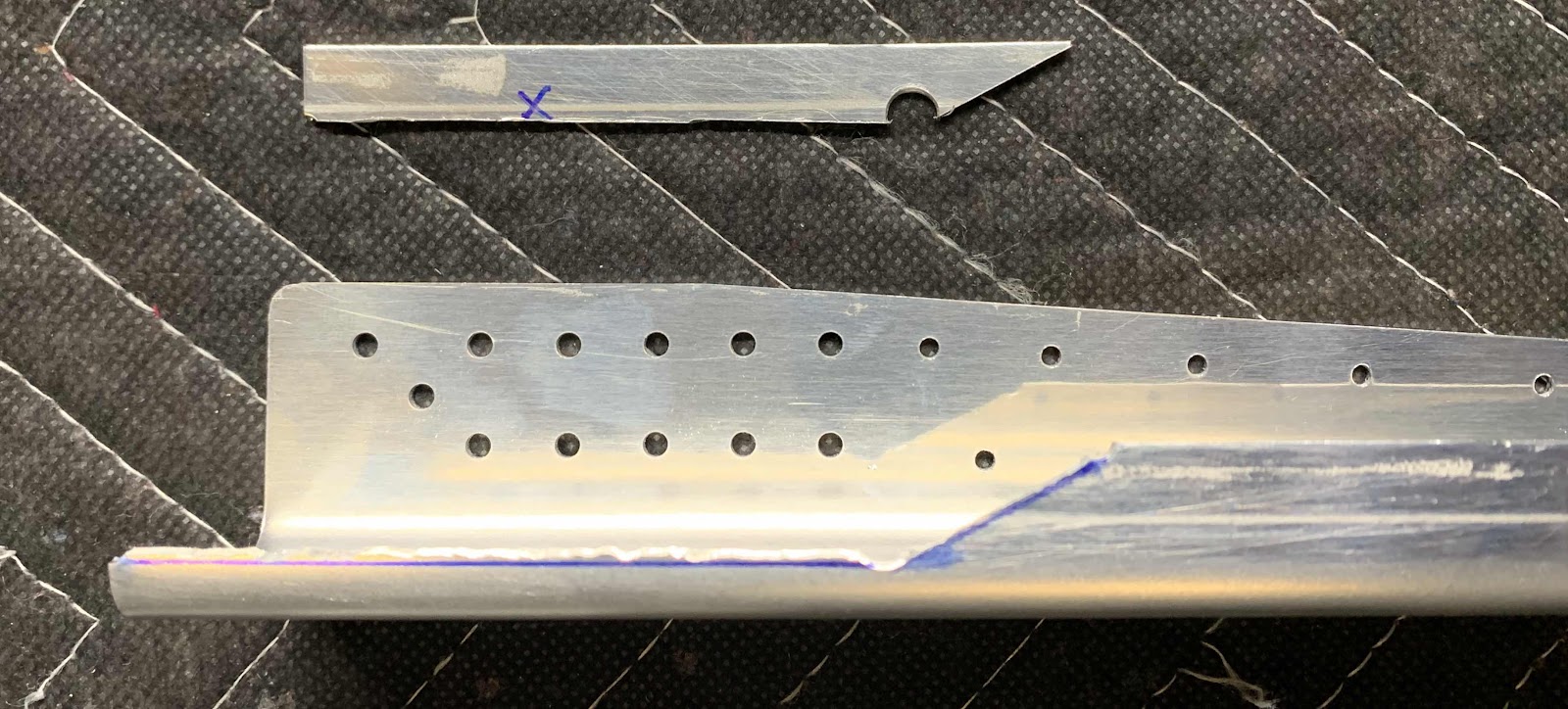
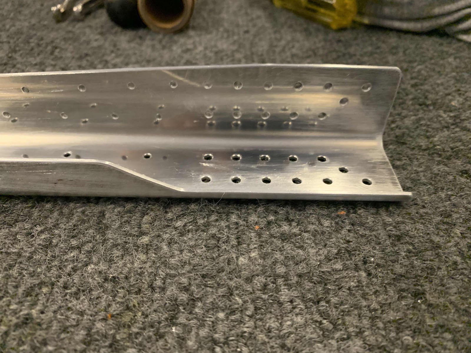
This is a close up of the area where material had to be removed (shown in the white).


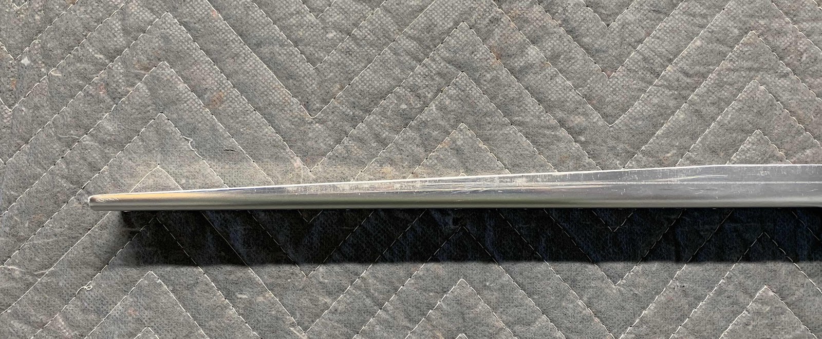
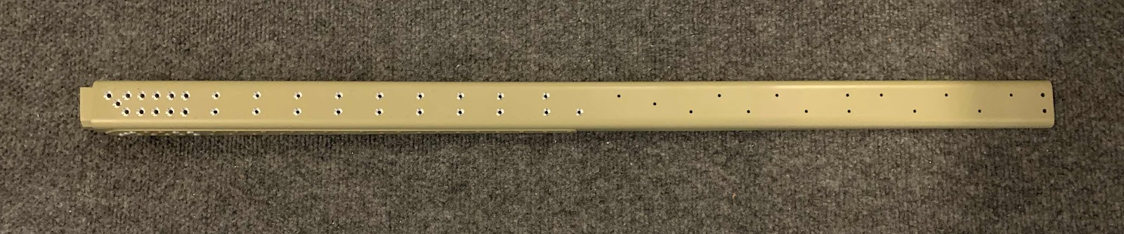
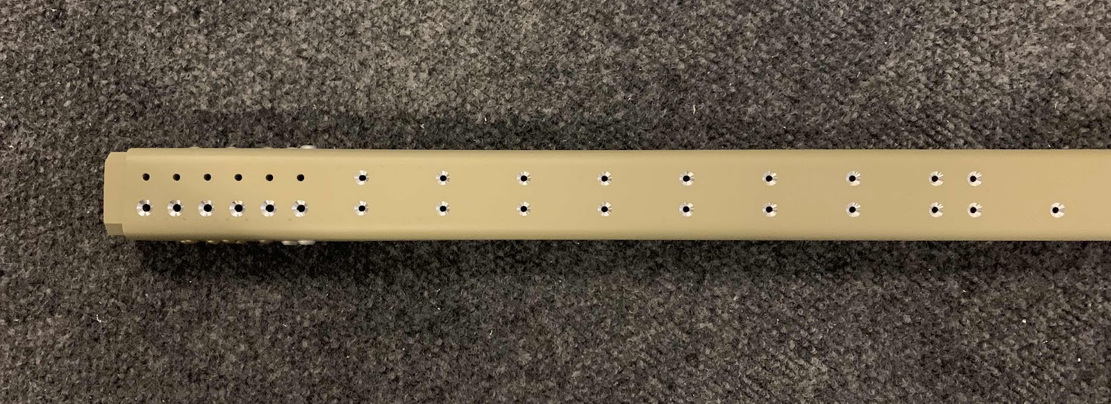
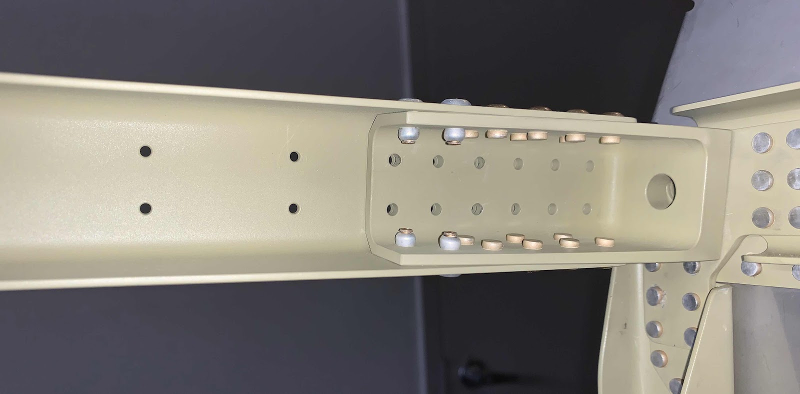
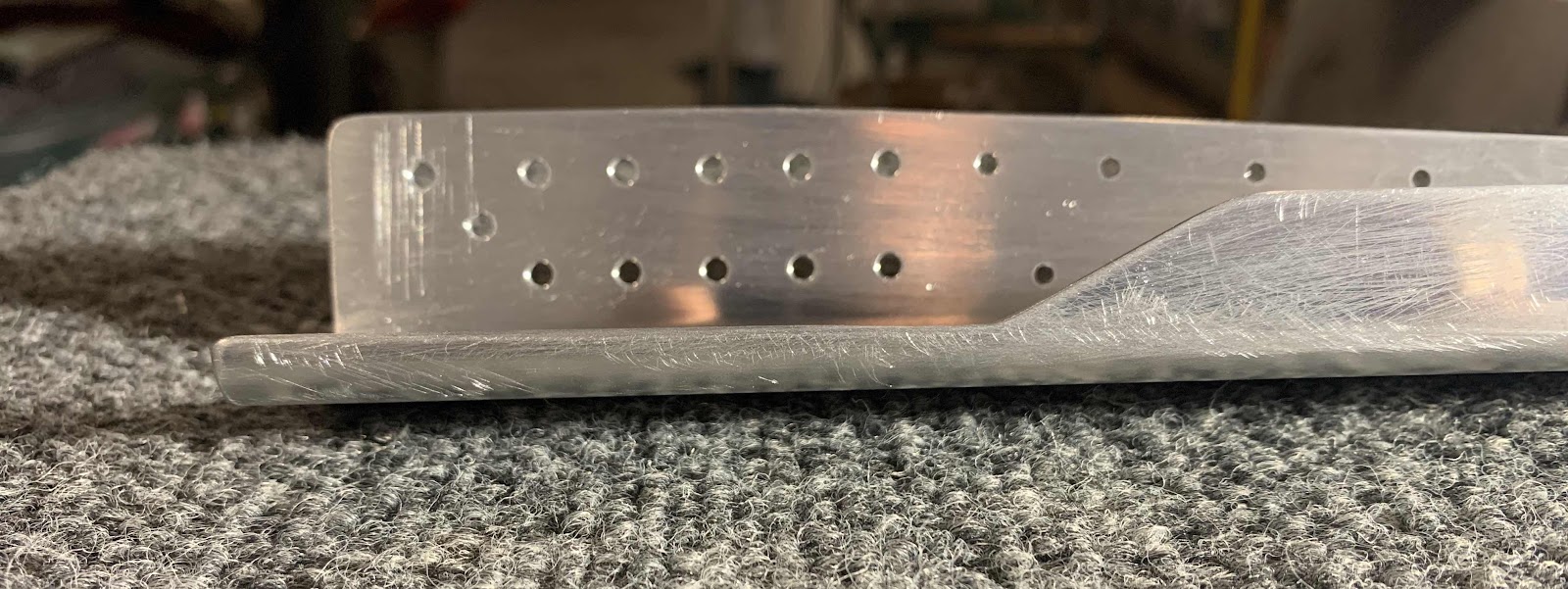
Here is the opposite end of the Longeron with the removed material.  You can see how the piece angles thinner from right to left.


Wednesday, October 23, 2019

Fuselage, FWD/MID Side Structure (Part 23)

Today, we started on the prep work for the Left Side Skin.  With the exception of the holes in the hatched areas, all the #30 and #40 holes were dimpled using a combination of the pneumatic squeezer and the DRDT-2.

Next, as shown in the plans excerpt, I put breaks in the four edges as indicated below.

Here is the Left Side Skin with all the completed work during this session.  The edge work is all that remains prior to being treated with Alumiprep, Alodine, and Akzo primer.

Monday, October 21, 2019

Fuselage, FWD/MID Side Structure (Part 22)

Yesterday was prime day.....today is countersink day.  Below are the F-01485-L & -R Center Section Side Plates.  All the #30 and #40 holes had to be countersunk (except the ones covered in orange tape) to accept the .032 Side Skins.  The large grouping of holes on each piece are the #30 holes and the rest are #40.  Once the stops are set on the countersink, the process went pretty quickly.

I used a couple of boards (actually wood from breaking down the crate one of the kits came in) on either side of the hole line to be countersunk for support and clamped the assemblies to the table.


Pictured below is the Left Lower Longeron Assenbly.  Many of the holes in this assembly also needed to be countersunk.  The group of holes on the left are the #30 holes and the rest are #40.  As you can see, only about half of the #40 holes get countersunk.

Below is the Right Lower Longeron Assembly.  After countersinking the appropriate holes, I discovered a “situation” I’m not entire comfortable with.  If you look at the three rivets I have inserted in three of the holes, you can see two of them don’t look right.  The rivet on the far right fits into the hole with no “gaps” around the rivet.  The left and center rivets have large “gaps” around the them.  After inspecting the remaining holes, many showed “gaps” around the rivets and looked oval (you can see this in the picture).  The best I can guess.....I wasn’t perfectly straight when these holes were Match-Drilled to 1/8”.  THIS IS OBVIOUSLY UNACCEPTABLE!  I could call Van’s and maybe get guidance on a “fix”, but it wouldn’t be right.  This area will be subject to higher stress loads and I want it to be built correctly.  So, since there are only three total pieces that make up this Assembly, I ordered replacement parts and will rebuild the Assembly correctly.

Below is the Left Upper Longeron Assembly and also required countersinking.  The six holes on the far left (bottom) are the #30 holes that needed countersinking (upper holes are not countersunk).  The remaining holes in the Assembly are #40 and all required countersinking.  The Right Upper Longeron Assembly was completed the same way.

Since I discovered the problems holes in the Right Lower Longeron Assembly, I inspected all the holes in the other three Longeron Assemblies.  All of the other holes were perfect and no “gaps” were present around the rivets.

Sunday, October 20, 2019

Fuselage, FWD/MID Side Structure (Part 21)

All the parts and pieces that were prepared over the past few days were Akzo primed today.  These are all the parts.....

.....F-01413-L & -R Stiffeners.....

.....F-01492-L & -R Fuselage Side Ribs.....

.....F-01491-L & -R Fuselage Side Ribs.....

.....F-01422-L & -R Fuselage Side Ribs.....

.....F-01420-L & -R Arm Rests.....

.....C-01422T & B Canopy Latch Brackets.....

.....F-01433-L & -R Flap Block Brackets.....

.....F-01460-L & -R Intercostals.....

.....F-01402-L & -R Side Frames.....

.....F-01400A-L & -R, F-01400B-L & -R and F-01400C-L & -R Skin Stiffeners.....

.....F-01461B-L, F-01461A-L, F-01461A-R and F-01461B-R Roll Bar Angles.

During the next session, I will begin preparing the F-01470-L & -R Side Skins.....dimpling, edge cleaning, Alumiprep, Alodine and Akzo prime.  Once that is completed, we can start putting stuff together.

Saturday, October 19, 2019

Fuselage, FWD/MID Side Structure (Part 20)

I continued, and finished, working on the parts and pieces from Thursday.  All 26 pieces are shown on the table below and have been dimpled, separated and edge cleaned.

One of the pieces (shown in the plans excerpt below) had to be separated into four parts.....the F-01461A-L & -R and F-01461B-L & -R Roll Bar Angles.

Here are the four completed Roll Bar Angles after being separated and sanded to the appropriate sizes.  Each one of the pieces have been marked with their corresponding part numbers.  Now, upon closer inspection, you can probably see the two center pieces have “notches” in them on the two sides facing each other (circled in black).  I originally thought these “notches” would get sanded out of the piece during preparation.  However, after some measuring, I determined there would not be enough edge distance if I sanded them away.  Additionally, if you look at the plans excerpt above, the hatched area that needs to be removed goes right through the center of the hole (that makes these notches) and doesn’t appear to have the “notches” removed.  So, based on there not being enough edge distance and from the illustration in the plans.....my pieces have “notches”.


Here is an example showing the F-01461A-L Roll Bar Angle showing a bottom width of 57.20mm as directed in the plans.

To get the measurements exactly right, I used a new tool.  Pictured below is the Milwaukee M12 Cordless Multi-Tool and it comes with several attachments.  As the name suggests, it can be used for multiple jobs.....flush or plunge cuts, a grinder, GROUT REMOVAL, and/or a sander.  I used the 60 grit and 240 grit sanding pads to sand the edges of the Roll Bar Angles to the required measurements in the plans.  This tool worked outstanding!  It saved a lot of time and elbow grease than doing it by hand.  I just wish I had this tool (now officially called the “Grouter”) the last couple of years of the build.  Anyway, I have it now.....

Once all the prep work on the parts was completed, I treated them all will Alumiprep and Alodine.  They are all now handing up over night to dry and tomorrow I will spray them with Akzo primer.


Friday, October 18, 2019

Fuselage, FWD/MID Side Structure (Part 19)

Not much to show from tonight’s session.  I continued preparing all the parts and pieces in the picture from yesterday....almost finished.  Once I’m all done, they will get treated with Alumiprep, Alodine and Akzo primed.

Thursday, October 17, 2019

Fuselage, FWD/MID Side Structure (Part 18)

I spent tonight’s session by beginning the prep work for all the parts shown in the picture below.  Many of the parts needed to be separated into multiple parts and pieces.  Once they are all separated, there will be a total of 26 individual parts.  After completing this session (and the next session) all the parts will be separated, dimpled and edge cleaned.

1.  F-01400A-L & -R, Skin Stiffeners
2.  F-01400B-L & -R, Skin Stiffeners
3.  F-01400C-L & -R, Skin Stiffeners
4.  C-01422, Canopy Latch Brackets
5.  F-01433, Flap Block Brackets
6.  F-01422-L & -R, Fuselage Side Ribs
7.  F-01491-L & -R, Fuselage Side Ribs
8.  F-01492-L & -R, Fuselage Side Ribs
9.  F-01413-L & -R, Stiffeners
10.  F-01461A-L & -R, Roll Bar Angles
11.  F-01461B-L & -R, Roll Bar Angles
12.  F-01460-L & -R, Intercostals
13.  F-01420-L & -R, Arm Rests


Wednesday, October 9, 2019

Fuselage, FWD/MID Side Structure (Part 17)

Today’s session was not very involved or long, but will set up the next session.  I clecoed the Upper Longeron Assembly, Lower Longeron Assembly, and F-1402-L Side Frame to the F-01470-L Side Skin.  Here is a couple of pictures of the Fuselage after the Side Skin was clecoed into place.


Tuesday, October 8, 2019

Fuselage, FWD/MID Side Structure (Part 16)

The F-01418A-L & -R Longerons and F-01488-L & -R Upper Engine Mount Brackets were treated with Alumiprep, Alodine, and sprayed with Akzo primer during the last session.  During today’s session, they were riveted together using four CR3213-5-5 cherry rivets and 14 AN470AD4-6 solid rivets.  

Pictured below is the right “Upper Longeron Assembly” showing the manufactured heads of the installed rivets.....

.....and the bottom side of the Upper Longeron Assembly also showing the manufactured heads of the installed rivets.....

.....and the “inside” of the Upper Longeron Assembly showing the shop head side of the rivets.

The three pictures below show the same angles, but on the left Upper Longeron Assemby.


The next step was to prepare the left side piano hinge for the lower cowling.  When the kit was delivered, it contained two 1/8 Piano Hinges approximately 8’ long.  So, to start a length of 20 1/8” piece was cut as instructed.  Additionally, only the lower 16 eyelets are need and the rest were removed (4 1/2 of them).  The picture below shows the piece cut to length and the appropriate eyelets removed.

Next, a 3/32 (#40) pilot hole had to be drilled in the Piano Hinge.  The plans provided the appropriate measurements for the location of the hole.....99.2 mm from the top and 6.4 mm from the outside edge.  I marked the hole (which made the plus below), used a center punch to mark the center and drilled the #40 hole.  Lastly, a reference line 2.4 mm was drawn lengthwise on the inside edge.

Sunday, October 6, 2019

Fuselage, FWD/MID Side Structure (Part 15)


Fuselage, FWD/MID Side Structure (Parts 14 - 10)

September 18, 2019 (Part 10)

I began work on the CS-00006 Control Column during this work session.  There will be four VA-146 Flange Bearings attached/riveted to Control Column (two on each side).  Initially, the plans state to use a step drill to enlarge the center holes in the Control Column as necessary to fit the Flange Bearing.  All four holes needed a little bit of work because of the power coating.  Instead of using a step drill, I use some 220 grit sand paper.  After a little bit of sanding, all four Flange Bearings fit into the center holes of the Control Column very nicely.  

Once I got the Flange Bearings to fit properly, the next step was to final-drill #12 the four holes circled below.  Here are a couple of pictures showing the Flange Bearings attached to the Control Column.


Next, with the Flange Bearings clecoed to the Control Column, all the holes common to both pieces were final-drilled #30.

The last step for this session was to trim the forward left edge of the Flange Bearing to match the Control Column (shown below).  I marked the area of the Flange that needed to be removed, used a bench grinder/Scotchbrite wheel to remove most of the material, and made the final adjustments using 220 grit sandpaper.  Here is completed Flange Bearing.

- - - - - - - - - - - - - - - - - - - - - - - - - - - - - - - - - - - - - - - - - - - - - - - - - - - - - - - - - - - - - - - - - - - - - - - - -
September 21, 2019 (Part 11)

I wanted the Flange Bearings to be Akzo primed and painted white to match the Control Column.....and for corrosion protection.  So, I put some orange take over the Bearings and painted them up.  Here is how I did it.....

Once the Flange Bearings were dry, they were riveted to the Control Column.  Each Bearing received six AN470AD4-6 rivets (24 total).  Here is an overall view of the installed Bearings on the Control Column.

Here is a close up of one end of the Control Column showing the manufactured and shop head side of the rivets.....

.....and the other side.

After the Flange Bearings are installed on the Control Column, the whole thing gets bolted to the Bearing Bracket Assemblies in the Forward Fuselage Lower Structure as shown in the two plans excerpts below.


Here is an overall picture of the Control Column installed in the Forward Fuselage Lower Structure.....

.....and a close up.

The gap where you are supposed to install washers and/or shims (shown in the second excerpt above) between the Control Column and the Bearing Bracket Assemblies......my fingers were too big to fit.  So, I fashioned this technique to install the washers.  I took some orange tape, tapped a washer on each end.....

.....folded it over on itself.....

.....and slide the washers in place.  Once the washers were in place, I pulled the tape up and “released” the washers.


- - - - - - - - - - - - - - - - - - - - - - - - - - - - - - - - - - - - - - - - - - - - - - - - - - - - - - - - - - - - - - - - - - - - - - - - - -
September 29, 2019 (Part 12)

According to the plans, the F-01418A-L & -R Longerons get “twisted”.....and Mike and Ike are going to help!!!!!

Here is how the plans say to do it.....


Here’s where Mike is going to go.....

.....and here is where Ike is gonna go!

They are positioned along the Longeron (both the right and left will be “bent” the same.....just in the opposite direction)!

So, now for the “twist”.....I clamped the Longeron with Mike into the bench vice.....

.....and Ike with a shim of wood and a C-clamp.

Then, I used elbow grease to rotate the C-clamp in the appropriate direction to make a permanent 10 degree “twist” in the Longeron.  To verify the 10 degree twist, I used a digital protractor.  The final number for the left Longeron was 10.0 degrees and the final number for the right Longeron was 10.1 degrees.

- - - - - - - - - - - - - - - - - - - - - - - - - - - - - - - - - - - - - - - - - - - - - - - - - - - - - - - - - - - - - - - - - - - - - - - - - -
September 30, 2019 (Part 13)


- - - - - - - - - - - - - - - - - - - - - - - - - - - - - - - - - - - - - - - - - - - - - - - - - - - - - - - - - - - - - - - - - - - - - - - - - - - - - - - - - -
October 2, 2019 (Part 14)