This blog was created to memorialize the building process of my Van's Aircraft RV-14 and to satisfy the requirements for certification in the Experimental Amateur Built Aircraft category. It will also serve as a central location for ME to reference in the future on processes and techniques I used during the build. Additionally, it will allow my family, friends, and other interested builders the opportunity to follow along during my build…..and might be helpful to someone along the way.
All of the Alumiprep and Alodine treatment was completed on the 12 Outboard Leading Edge Ribs during the last session. So, today I primed the Ribs with Akzo. Additionally, four of the Ribs (two on each Outboard Leading Edge) that will make up part of the Landing Light bay needed to be painted flat black. The two pictures below show the before and after.
During the next session, I will finish the edge work on the Left Outboard Leading Edge Skin and complete the Alumiprep and Alodine treatment on both Outboard Leading Edge Skins. Then, both Skins will get primed with Akzo and the Landing Light Bay will get painted with flat black.
The 12 Outboard Leading Edge Ribs were treated with Alumiprep and Alodine during today’s work session. The six Ribs on the left are for the Left Outboard Leading Edge and the six on the right are for the Right Outboard Leading Edge. I used the same dipping method as I have for all the Ribs up to this point and they are now hanging up to dry overnight.
I will begin Akzo priming during the next session.
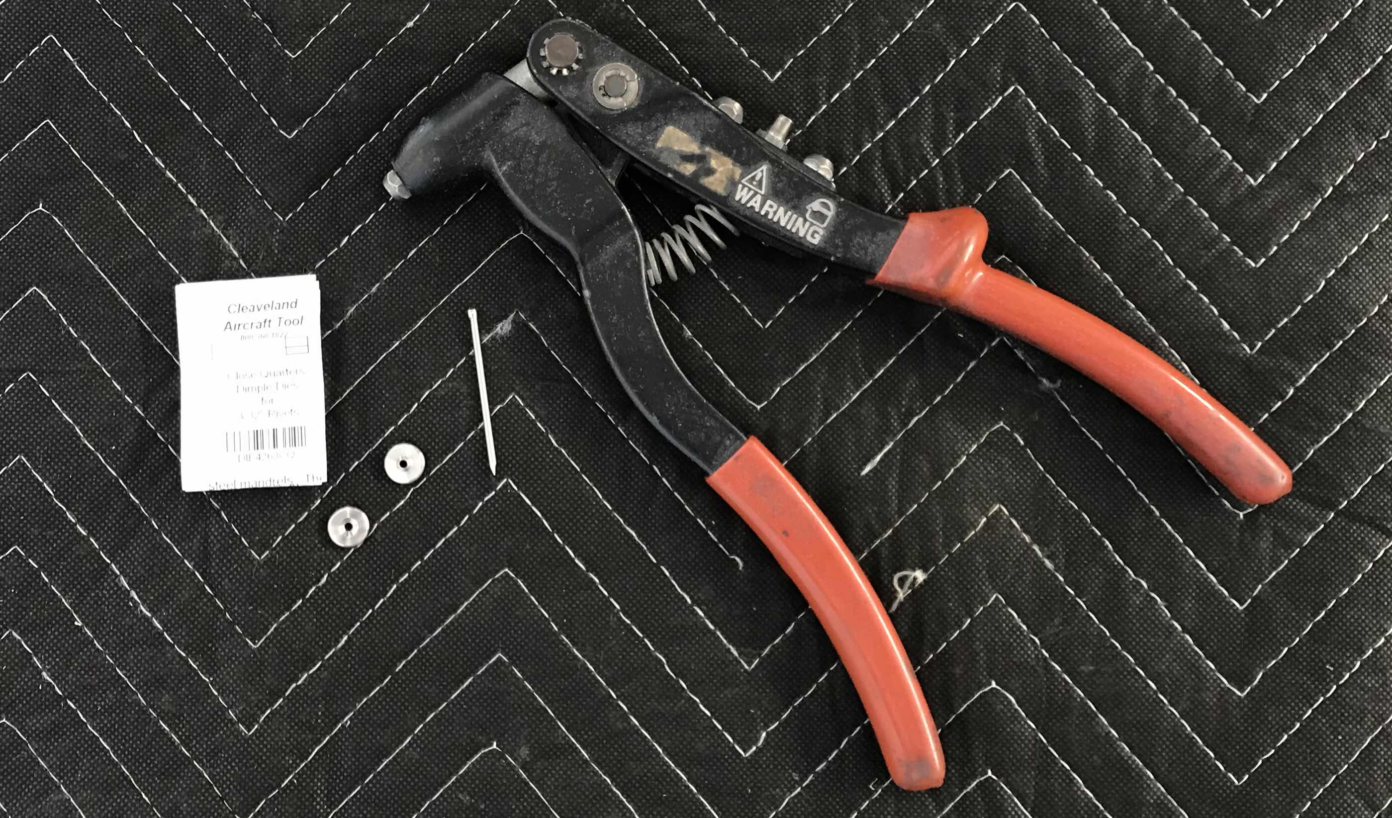
I finished dimpling the Right Outboard Leading Edge Skin during today’s session. I used the DRDT-2 to dimple most of the holes; however, a few holes were to close to the leading edge bend to use the machine. So, to dimple these holes, I used the Cleaveland Aircraft Tool Close Quarters Die Set.
Here is what I used.....
This is a short video from Mike at Cleaveland demonstrating how to use the tool correctly.....
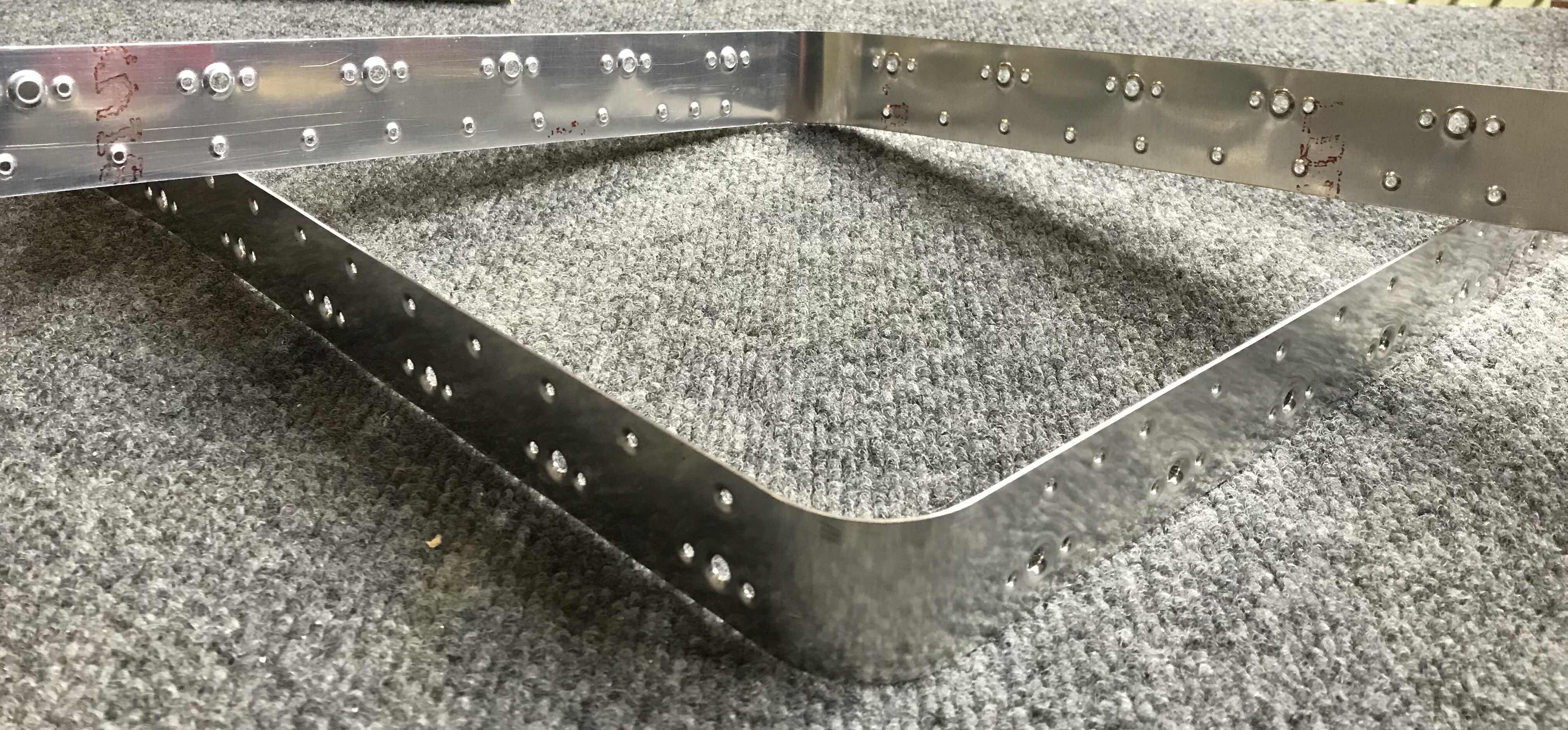
Lastly, here is a couple of shots of the Right Outboard Leading Edge Skin after it was completely dimpled. The last “process” is the clean the edges of the Skins..
Very short session today. I started dimpling the #40 holes in the Right Outboard Leading Edge Skin with the DRDT-2. I was able to complete one side of the Skin and I’ll complete the other side during the next session.
I started tonight by completing the dimpling of the #40 holes in the Left Outboard Leading Edge Skin. As I mentioned previously, I used the pneumatic squeezer to dimple all the holes I could reach with a 3” yoke. Today, I had to use the DRDT-2 to get all the remaining holes and was able to complete all the required dimpling. Here is the Skin is the cradles. Next, I cleaned all the edges.
Pictured below is the Landing Light opening that was pre-punched in the Skin by Van’s. These edges also need to be cleaned and I used 220 grit sandpaper to complete all the required sanding on the Skin.
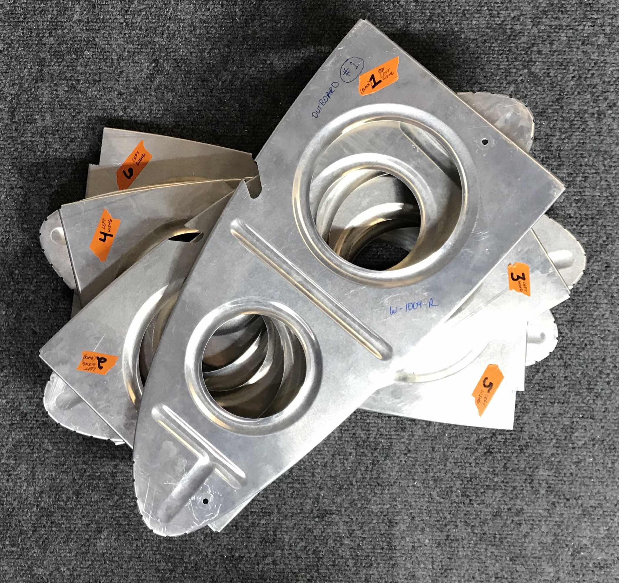
In the near future, I will be preparing the Outboard Leading Edge Ribs with Alumiprep, Alodine, and Akzo Primer. Additionally, a few Ribs in each Landing Light bay will get sprayed with flat black paint. Just like with the previous Wing ribs, I numbered and labeled each of these Ribs corresponding to where they were fit to the outer Skin. Below are the Ribs for the Right Outboard Leading Edge.....
.....and the Ribs for the Left Outboard Leading Edge.
So, short of Alumiprep, Alodine, and Akzo Primer, the Left Outboard Leading Edge Skin is finished and prepped. I will work on the Right Outboard Leading Edge Skin during the next session.
After priming and painting the pieces yesterday, today’s session was all about riveting. I started with the four Backing Plates and the Access Hatch Doubler as shown in the excerpt below.
Each Backing Plates used four K-1000-06 nutplates and were attached with AN426AD3-3.5 rivets. Pictured below are the four Backing Plates.....two on the front side and two on the rear side.
Because the Backing Plates will be installed with the landing assemblies (and be visible through the landing light lenses), I also wanted the rivets and nutplates to be black. You can barely see, but the manufactured heads of the rivets and the nutplates have been painted flat black.
The Access Hatch Doubler 10 K1100-06 nutplates and AN426AD3-3.5 rivets. This Doubler will ultimately be painted when the entire airplane gets painted, so it will remain the green Akzo primer color. Here is the front side of the Doubler showing the manufactured heads installed on the nutplates.....
.....and the rear side.
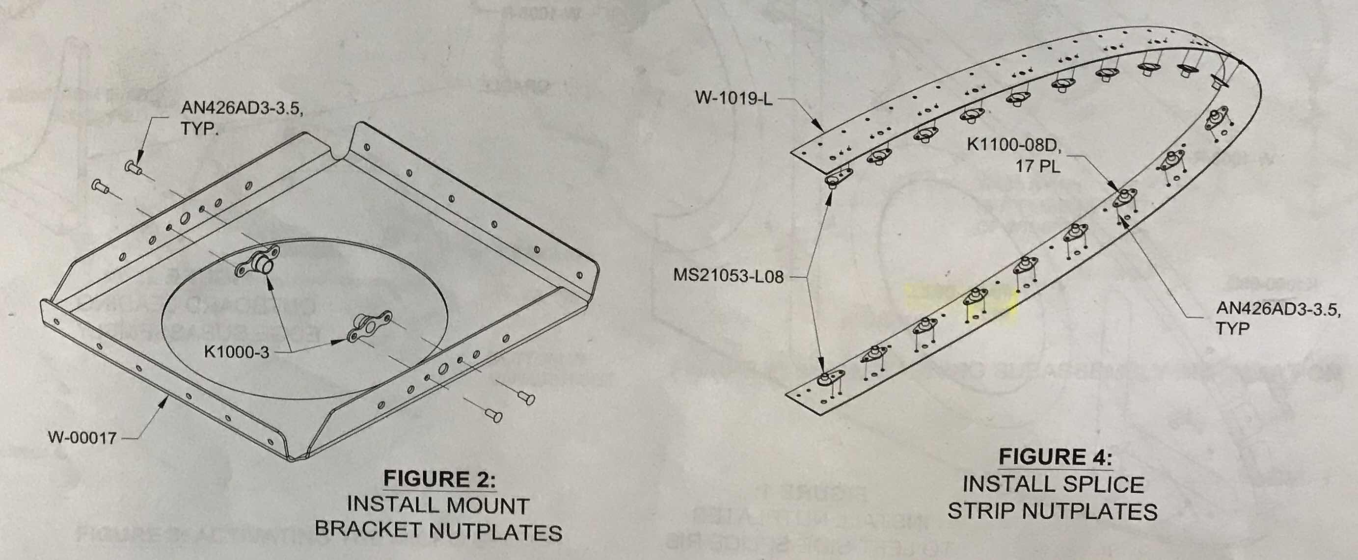
Next to receive rivets were the two Mount Brackets and the two Splice Strips as indicated in the excerpt below.
The Mount Brackets only had two K-1000-3 nutplates (each) and were installed with AN426AD3-3.5 rivets. Just like with the Backing Plates, I painted the manufactured head of the rivets and the nutplates flat black.....for the same reason.
The Splice Strips each received 19 nutplates.....(17) K1100-08D and (2) MS21053-L08. Both types of nutplates used the same AN426AD3-3.5 rivets. Here is a picture of both sides of the Splice Strips.
With all the nutplates installed on the nine pieces, I shifted work back on the Leading Edge Skins.....specifically, the Leading Edge Skins. Just like on the Right Outboard Leading Edge Skin, I dimpled all the holes I could reach with the pneumatic squeezer. I will dimple the remaining holes with the DRDT-2 machine.
Today, I primed all 10 pieces mentioned in my previous post. Below, are the two Splice Strips with the 19 nutplates clecoed into place to each one.
Here is the Access Hatch (right) and Access Hatch Doubler (left). The Access Hatch Doubler also has the 10 required nutplates clecoed in place.
Lastly, the plans suggest to paint the Wing bay that will house the landing light on each Wing. Below are six of these pieces. On the left, are the Mounting Brackets (landing lights will eventually be mounted to them.....one for each Wing). On the right, are the four Backing Plates that will hold the Landing Light Lenses to the inside of the Wing. I initially primed the six pieces with Akzo Epoxy Primer and then used a flat black spray paint for the black color. There are still a couple more pieces associated with this Wing bay that will need to be painted flat black, to include the corresponding section of the Outboard Leading Edge Skins.
Today, I added the two Splice Strips to the Access Hatch, Access Hatch Doubler, two Mount Brackets, and four Backing Plates and they all received Alumiprep and Alodine treatments.
Tonight was a relatively short night, but I was able to prepare a couple of pieces.
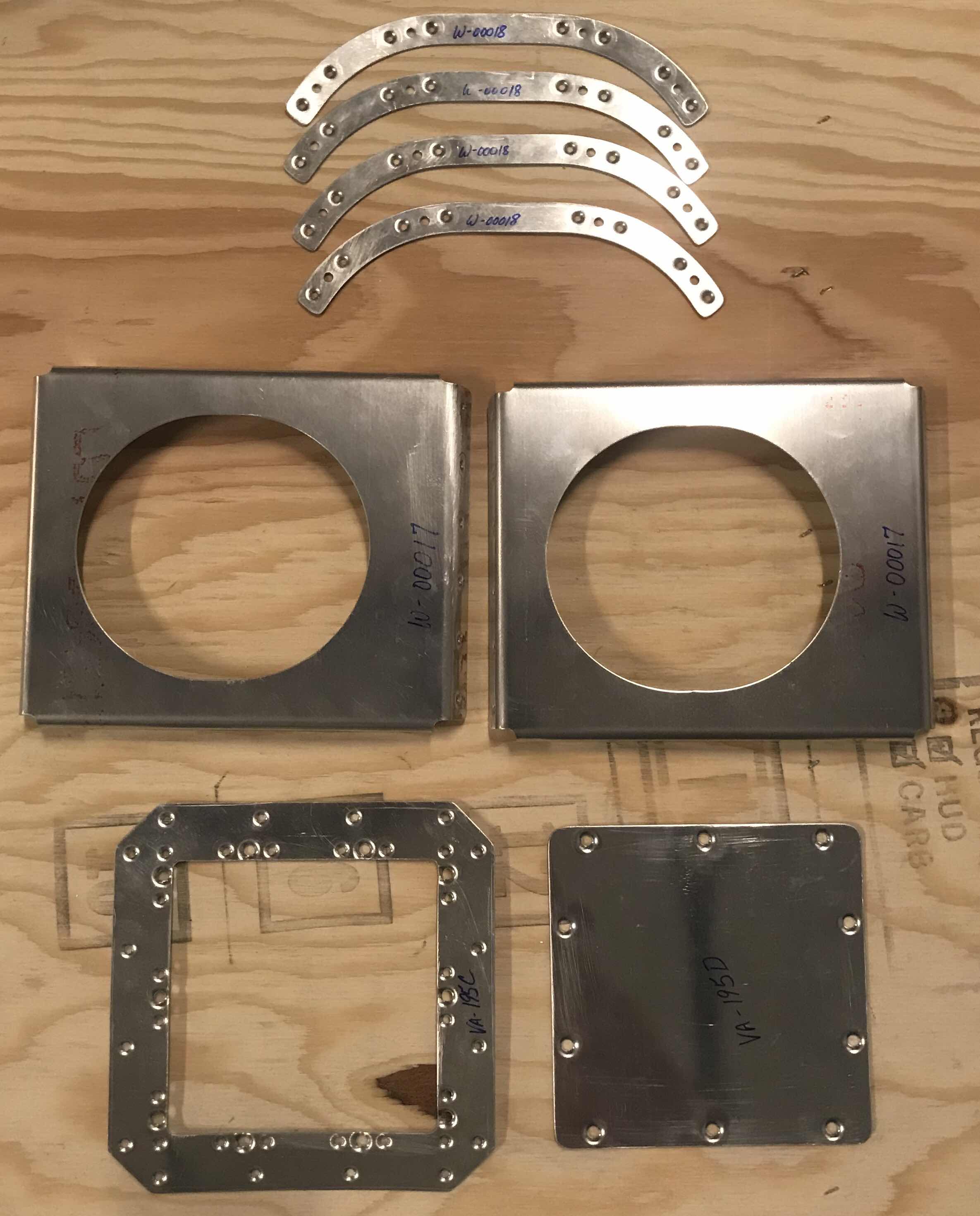
To start, I removed the reference tabs from the VA-195C Access Hatch Doubler as shown in the plans excerpt above. Next, the holes in the Access Hatch Doubler and the VA-195D Access Hatch were deburred and the edge work was completed.
Lastly, I completed the edge work and hole deburring on three of the four W-00018 Backing Plates. These Backing Plates will be used to hold the Landing Light Lenses to the Left and Right Wings. (Later in this Section).
Another short session today, but like I said in my previous post.....I’m still making forward progress. The next step in the plans is to dimple the Outboard Leading Edge Skins. I started the process today on the Right Outboard Leading Edge Skin. I still have to complete the dimpling process for the whole Skin, but I started by dimpling the holes I could reach with my pneumatic squeezer and a 3” yoke (I will do the same thing on the Left Outboard Skin). I was able to get all the holes near the edge of the Skins and a few on the Rib seams. I will use the DRDT-2 for the remainer of the holes, as the pneumatic squeezer won’t reach them.
Here is just a few shots of each end of the Right Skin and an example of some of the holes I was able to squeeze.
Not a lot of progress tonight, but progress none-the-less. I deburred all the holes I previously Match-Drilled in the Flanges, dimpled them with sub-structure dimple dies, and completed the edge work on the two Outboard Leading Edge J-Channels. They are now ready for Alumiprep, Alodine, and Akzo Primer.
Tonight, I prepare the Right Wing’s Outboard Leading Edge in the same manner as I did in Parts 6 and 7 for the Left Outboard Leading Edge. The J-Stiffener was Match-Drilled to the Skins and the final hole in the Wing Ribs were also Match-Drilled to the Skins.
Both Outboard Leading Edges have been disassembled and I will start the process of deburring all the holes I drilled during the last several sessions. The Left and Right Outboard Leading Edge Skins will be dimpled in the next few sessions.
During tonight’s short session, I began the process of installing the Ribs into the Right Wing’s Outboard Leading Edge. This was done is the same fashion as the Left Wing’s Outboard Leading Edge as shown/described in Part 5.
Here are a few pictures of the Right Wing’s Outboard Leading Edge in the cradles with the Ribs clecoed into place.
In the picture below, you can also see the J-Stiffener clecoed to the Skin.
Well, with 1,576 rivets to install in the Top Wing Skins, you don’t turn down free labor from experienced help. My buddy Doc offered to help, so he was hired (and about halfway through, Jeff helped me finish.....I guess he was hired also). We started on the Right Wing with the Inboard Top Wing Skin. As the plans instructed, we clamped the Main Spar down to the work table and placed wood under the Spar at various locations to keep it level. I used a level at several places along the Spar to ensure it remained straight. Additionally, we were cautious not to introduce any warping or twisting to the Wing. Below are a couple pictures of how we did it.....
The plans state in order to get the tightest Skins possible to start riveting in the center of the Skin and work your way to the tip and root. The picture below shows the completed Inboard Wing Skin, minus the horizontal J-Stiffener in the center (which will be installed after the Skins).
Initially, we followed the guidance from the plans and back riveted the Skins using a large bucking bar and extended back rivet set. This method required the Flanges of the Wing Ribs to be slightly “moved” out of the way to keep the set straight on the rivet. As we progressed toward the top and bottom (forward and aft) of the Wing Rib, it became harder to move the Wing Rib. So, we transitioned to the old method of shooting with a rivet gun and bucking bar. This way seemed to work out better and produced a better product.....and went faster. I plan on shooting all the rivets from here on out.
Here is the opposite side of the completed Inboard Wing Skin. If you look closely, you can see the shop heads of the rivets along the Flanges of the Wing Ribs.
On the inboard edge of the Inboard Wing Skin, there are eight nutplates that get installed on the Flange of the Wing Rib. Here you can see seven of them.....one is hidden under the Aileron Torque Tube Support Bracket Assembly.
Well, my free labor had to go.....so, until next time.
I Match-Drilled all the #40 holes in the J-Stiffeners yesterday for the Left Wing. To start today’s session, there were 12 additional holes that needed Match-Drilling. These were the top holes (or in this case, the most forward holes) on the six Ribs. Two examples of these locations are circled in the picture below.
The next step in the plans was to prepare the slot in the Leading Edge that would contain the Stall Warning System. To make this modification easier on me (and achieve a better result), I laid the assembly down on its side while still in the cradles. This would allow me to work from the “outside” of the assembly “in” versus the other way around. This way, I had much more room to work.
Circled in the picture below are the two pre-punched holes in the Leading Edge Skin that will need to be modified for the Stall Warning System.
To start, these two holes had to be enlarged to #10.
Next, the material between the two holes had to be removed. To do this, I drilled several small #40 holes (as described in the plans) between the larger #10 holes. I then used a very small round file to file away the connecting material between those holes. For the final shape, I used a fine flat file and 220 grit sandpaper.
The two pictures below (one from the outside and one from the inside) show the final modification to the Leading Edge Skin for the Stall Warning System. I forced myself to go slow during this step and was very cautious not to remove too much material. I am very pleased with the results.
I ran out of clecos last night, so I was only able to cleco three of the Outboard Leading Edge Rib inside the Skin. To fix that “problem”, I went to Pan American Tools and picked up some more clecos. (Ironically, I ran out again....another story).
So, with the extra clecos, I was able to get all six of the Ribs the plans called for into place in the Left Wing’s Outboard Leading Edge. Additionally, I finished drawing the centerline on the two J-Stiffeners (plans excerpt on previous days post) as shown in the picture below.
The J-Stiffeners don’t come pre-punched from Van’s and requires the builder to make the necessary holes. To do this, the J-Stiffener is inserted into the channels in the Ribs and the single #40 hole (previously drilled yesterday), on the inside edge of the Stiffener, is clecoed to the Skin. Now, moving hole by hole, the centerline that was drawn on the Stiffener is centered in the pre-punched hole in the Skin.....then it’s Match-Drilled. A cleco is inserted after drilling each hole to keep the J-Stiffener as straight as possible. Pictured below is the inside edge of the J-Stiffener (on the inside) with the clecos inserted in the freshly drilled #40 holes.....
.....and here is the outside.
That completes the Match-Drilling for the J-Stiffener on the Left Wing. Tomorrow, there are several holes that need to be Match-Drilled in the Ribs and the same process will be repeated on the Right Wing in sessions to come.
During the last session, I cut away the two Splice Strips from the Left and Right Fuel Tank Skins. Tonight, I completed the prep work on the them. First, I had to remove the remaining material (nubs) from where it was connected to the Skin. I used an angle grinder with a sanding disk to file the majority of the material away. I then used 220 grit sandpaper to smooth the edges. After doing this for both Splice Strips, all the edge work is now completed.
The next step was to Final-Drill #19 the #8 screw attach holes in all the nutplate locations, debur the holes and dimple them. As previously stated, the plans warn to make sure the #19 (#8 screw) holes were properly deburred prior to dimpling. Apparently, these sized holes have a tendacy to crack if not deburred properly.
Next, the #40 holes had to be Final-Drilled (the plans didn’t call for this and went straight to dimpling), deburred and dimpled. Pictured below are the two Splice Strips (front and rear side) with all the completed work described above.
The first step in the plans for this section was to construct a pair of Leading Edge cradles.....they are finally getting some use. Pictured below is the Left Outboard Leading Edge Skin resting in the cradles. The cradles will hold the Leading Edge Skins (and Fuel Tank Skins in the next section) in place during this portion of the build.
I began clecoing the Ribs into place and here are the first three.