Thursday, January 17, 2019

Wings, Flaps (Part 10)

After allowing the primer to dry, it was time to rivet some stuff together.  

Below are the completed FL-1004-L & -R Nose Ribs and FL-1006 Doublers.  Each pair are held together with eight AN470AD4-4 universal rivets.  The Nose Rib on the left has two additional AN426AD3-4.5 flush rivets that were used to attach the MK1000-428 nutplate on the underside.  These rivets were very easy to install and I used my pneumatic squeezer with a 2” longeron yoke.

Next to be riveted were the Left and Right Hinge Pair Rib Assemblies.  The FL-1004-L & -R Nose Ribs were riveted to the FL-1007-L &-R Hinge Brackets with nine AN470AD4-4 rivets and are shown completed below.  These rivet installations were also easy and I used the pneumatic squeezer.

The next step was to install the four double flush AN426AD3-3.5 rivets that connect the Left and Right Hinge Pair Subassemblies.  In the picture above, the Hinge Pair Rib Assemblies are lined up and you can see the four corresponding holes that will receive the double flush rivets.  The plans instruct you to use the hardware that will eventually be installed in the holes at the bottom of the brackets to maintain the alignment of the Subassemblies during riveting.  

To complete the riveting process, I installed three clecos in the holes as shown below.  The wood you see in the picure below was left over from when I made the wing craddles earlier in the Wing construction.  I used the wood to fill the void between the two Brackets and a clamp to hold everything together.  With the clamp installed it form a “base” and allowed the whole assembly to “stand up” as shown below.  This made the riveting very easy to complete with the pneumatic squeezer.

Here are the Subassemblies after the rivets were installed.  The eight double flush rivets are shown in the circle below.  The rivets on the left show the manufactured heads and the ones on the right show the double flush side.

Wednesday, January 16, 2019

Wings, Flaps (Part 9)

The last session was Alumiprep and Alodine.  Today’s session was Akzo Primer.

Below is the FL-00003-L Spar and FL-00001-L Nose Skin.


Here is the FL-00002A Top Skin and FL-00002B Bottom Skin.  If you notice, the trailing edges of the Skins have an area that was not primed.  This area was taped off when the Skins were primed.  This is where the Skins will make contact with the trailing edge “V-Channel” and the adhesive (3M two-sided tape) will be applied.


These are the pieces that make up the Left and Right Hinge Pair Subassemblies.


And lastly, the Ribs.

Monday, January 7, 2019

Wings, Flaps (Part 8)

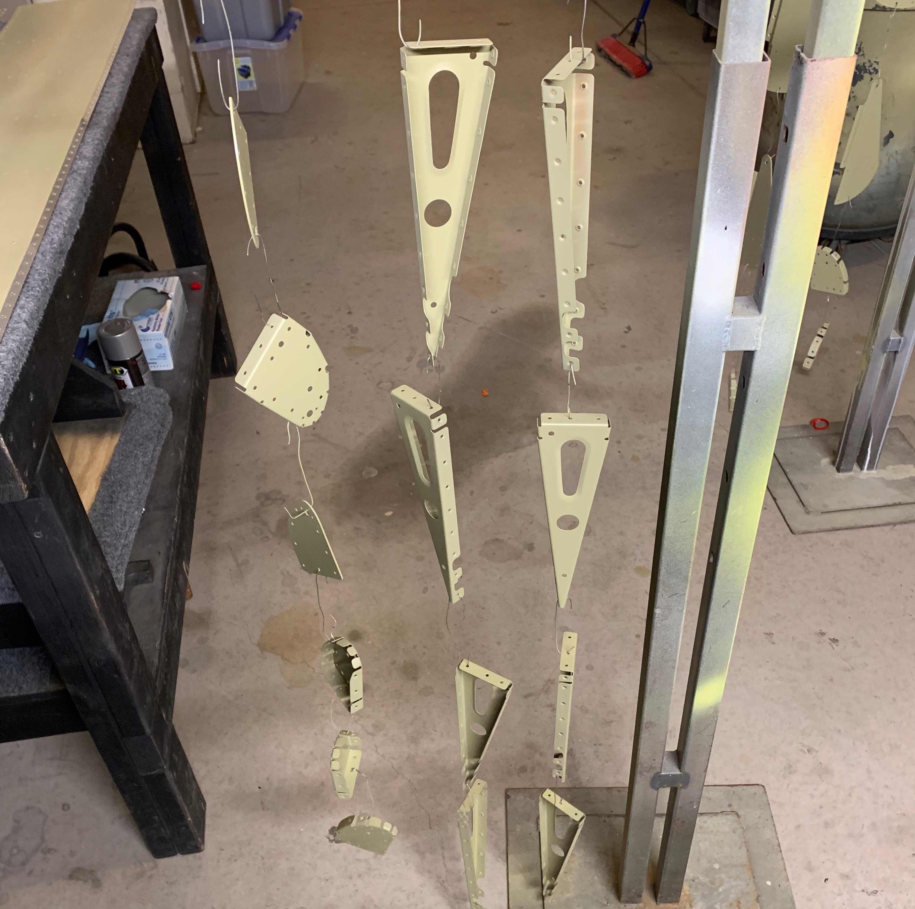
Not much to talk about tonight.  In Part 7, I finished the prep work for all the parts and pieces for the Left Flap.  Today, I treated them with Alumiprep and Alodine.  The three pictures below show all the parts handing up to dry.


Sunday, January 6, 2019

Wings, Fuel Tanks (Part 36)

In the last session, I taped off the Right Fuel Tank for Akzo Priming.  Guess what I did today?

Here is the Aft Baffle after priming and removing the tape.....

.....the Inboard side of the Tank.....

.....and the Outboard side of the Tank.

Here is the hardware that will be used to hold the Fuel Tank onto the Wing.  The hardware consists of 21 bolts (three AN3-5A and 18 AN3-4A) and 77 AN509-8R8 screws.


After allowing the primer to dry on the outside of the Fuel Tank, it was time to install it on the Wing.  The first step was to install the bolts through the Main Spar into the Fuel Tank Attach Zees as shown in the plans excerpt below.  (Part 34 shows some close ups of the installed bolts for the Left Fuel Tank).

To install the screws, I used the same method to install the Right Tank as I did for the Left Tank.  I took each screw hole.....

.....used a paint brush to brush on some of the primer.....

.....installed the screw wet.....

.....and used a rag with MEK on it to wipe away the excess.

After installing the 21 bolts and 77 screws, the Right Fuel Tank is finally installed on the Right Wing.

A view of the Outboard side of the Fuel Tank with Filler Cap.

And back to bed in the wing cradle to wait for the next step.

Section Complete

Saturday, January 5, 2019

Wings, Fuel Tanks (Part 35)

Prior to Akzo priming the outside of the Left Fuel Tank, I wanted to test fit the Tank to the Wing in case it need to be sanding.  Shown below is the Fuel Tank temporarily attached to the Left Wing.  The fit was perfect....almost!

The only area on the Left Fuel Tank needing a slight “adjustment” is located in the white circle in the picture below.  This is the area where the Fuel Tank Skin and the Inboard/Outboard Bottom Wing Skins meet.  This area had to be slightly sanded in order to sit flush against the Main Wing Spar and NOT on top of the Bottom Skins.

Once I completed the final test fit, it’s now time to Akzo prime the outside of the tank.  The four pictures below show the Tank taped off and ready to be primed.

Rear Baffle and Tank Attach Zees.....

.....Inboard side.....

.....Outboard side.....

.....and the Top Skin.

Thursday, January 3, 2019

Wings, Flaps (Part 7)

The last step needing to be completed on the Left Flap, prior to priming and assembly, is the countersinking of the FL-00008B-L (short) and FL-00008A-L (long).  These pieces are the Inboard and Outboard Trailing Edge Wedges as shown in the white circle below.

I used my Cleaveland Aircraft Tool Countersink Jig for RV Trailing Edge Wedge as shown below.  I clamped the jig and Wedge to the workbench to make the countersinks.  (Shown below is the FL-00008A-L (long)).

I had to make the countersinks differently than I originally wanted to.  For some reason, the pilot on my #40 countersink cutters would not fit into the holes needed to be countersunk.  I didn’t want to drill the holes and bigger, so I improvised.  I took the bit off of my deburring tool and put it on my drill (as shown below).

I determined 5.25 mm is the width of the countersink I want to use for the dimpled Flap Skins.

I also used my dimpled #40 template to verify the “fit”.

Here is the completed FL-00008B-L (short).  Both sides of the wedges will be countersunk to receive double flush rivets.

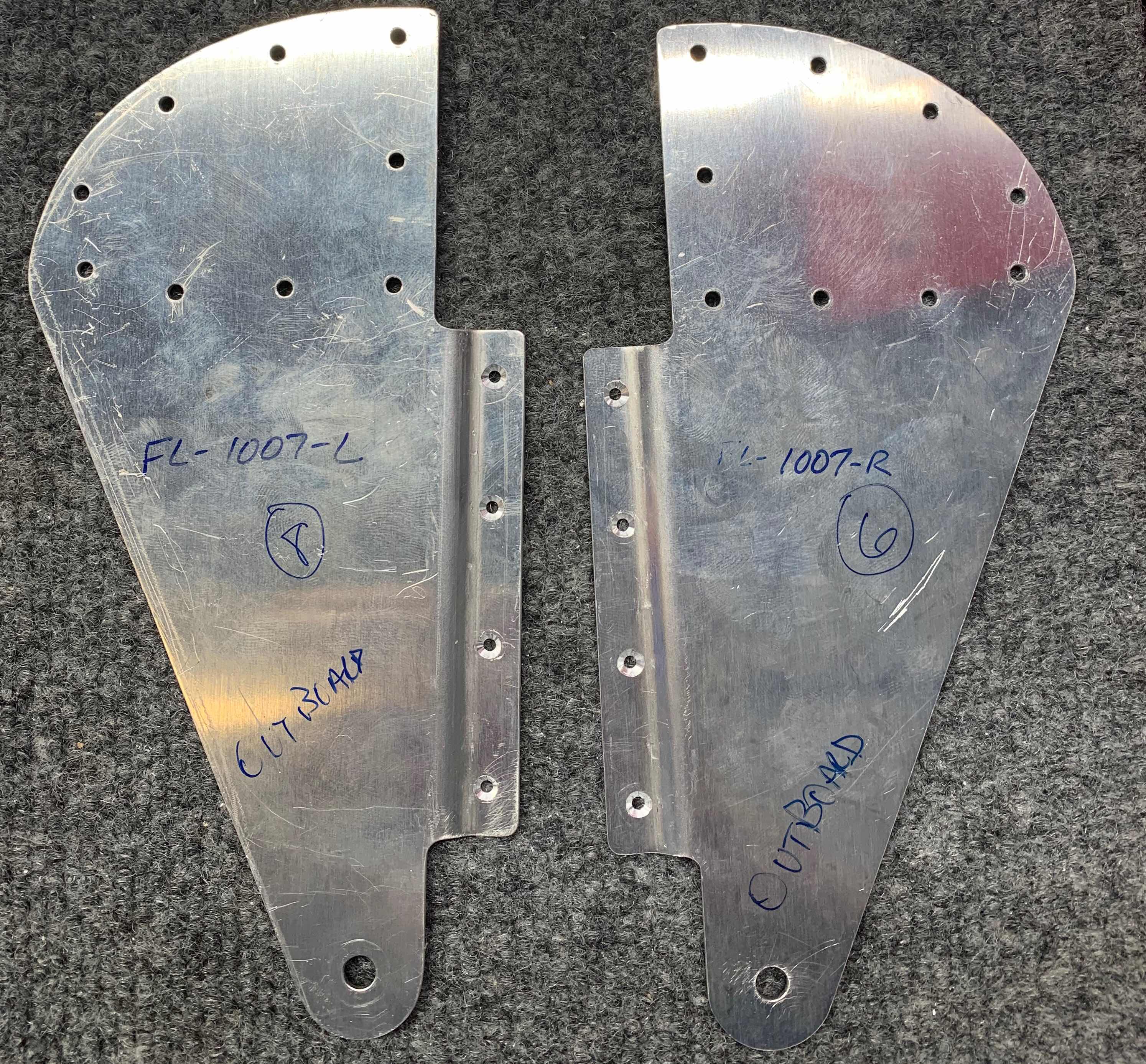
Lastly, the two FL-1007-L and two FL-1007-R Hinge Brackets also have to be countersunk for double flush rivets.  The holes that need to be countersunk are on the joggled flanges of the Brackets.  The plans describe how to make a drill jig to aid in using the countersink cage.  Since I already had my drill setup from making the countersinks in the Trailing Edge Wedges, I decided to use that again for the these countersinks.  To do this, I clecoed the two Brackets together (as shown below) and stacked to extra FL-1006 Doublers underneath.  This worked well and was exactly the perfect thickness.

Here is another view of my setup.

Here is the first completed Bracket.....

.....and the second.

Wings, Fuel Tanks (Part 34)

The work during this session was completed on Wednesday, January 2, 2019

The picture below shows the black Proseal I applied to Aft Baffle seams and Tank Attach Zees.  I’ve said it before, this might be complete overkill, but I do not want the tank to leak.


After allowing the Proseal to dry over some of the Christmas Holiday, it’s now time to leak check another portion of the Right Fuel Tank.  In Part 35, Jeff and I installed the Aft Baffle on the Right Fuel Tank (which is the focus of this leak check).  As with the Left Tank, all leak checks will be completed with actual 100LL Avgas....after all, isn’t that what’s going in it??  So, I filled the Fuel Tank with 5 gallons (which is enough to cover the Aft Baffle seams and a few Skin rivets not previous leak checked).  After the fuel was put in the Tank, I turned it “vertically” on the table.  In the picture below, you can see the Tank Attach Zee’s resting on the pieces of 2 x 6’s.  


Here is what it looks like “vertically” on the workbench.  I used a strap over one of the Wing Ribs to “loosely” hold the tank on the workbench in case it was bumped.  I also put cardboard down on the workbench to make it easier to spot any potential fuel leaks.

Here is the opposite side of the Tank.  The fuel level inside the tank is roughly 1/4 the way up the fuel cap on the lower right side of the Fuel Tank.  

And lastly, here is the inboard side of the Fuel Tank.  I temporarily installed the orange hose onto the tank’s air vent to vent the tank while it was sitting on the workbench being leak checked.

This is the final leak check that needs to be completed on the Right Fuel Tank.  If all checks out, the next step is to Akzo Prime the outside of the Tank prior to installing it on the Right Wing.

Tuesday, December 25, 2018

Fuselage Kit Ordered

!!!!!MERRY  CHRISTMAS!!!!!

ANOTHER big step!!!!!

On Friday, December 14, 2018, I completed the Fuselage Kit Order Form and emailed it to Van’s.  The Van’s website advises there is a 10 week lead time as shown below.  That will give me some time to finish the Wings prior to the next kit arriving.

As with all the other kits, I put down a 25% deposit.  The remaining balance will be charged prior to the kit being shipped in February.

*****Another motivational picture from Van’s Aircraft.....keep squishing them rivets*****
(Photo by Van’s Aircraft)

Friday, December 14, 2018

Wings, Fuel Tanks (Part 33)

Well, after a couple of months, Jeff and I were able to continue the work on the Right Fuel Tank.  During this session, we installed the seven T-1012 Tank Attach Zees and the T-00002 Tank Baffle.  As the instructions described, we applied a bead of Proseal on the Fuel Tank Skin from the Tank Baffle rivet holes forward.  By doing this, the Tank Baffle will  act as a “squeegee” and push the Proseal forward when installed.  Additionally, Proseal was applied to the aft flanges of the seven Tank Ribs.

Next, we installed clecos in EVERY hole that will be receiving a rivet.  Once the clecos were installed, we started riveting the Tank Baffle to Tank Ribs (starting from the center Tank Attach Zee, then working outward in both directions) and finished with the Tank Baffle to Tank Skin rivets (also starting in the center and working outward in both directions).  As with the Left Fuel Tank, the Right Fuel Tank will be receiving a combination of AN470AD4-4 and AN470AD4-5 solid rivets and AD-41H and AD-42H blind rivets in the locations indicated in the plans excerpt below.


Here is a aft section of the Right Fuel Tank after all the rivets have been installed.  In this view, you can see the seven Tank Attach Zees and their corresponding rivets.  For this installation, the closed end of the AD-41H and AD-42H blind rivets were “twirled” in Proseal prior to installation.  Additionally, you can see some of the black Proseal where the Tank Baffle and Tank Skin meet.

Here is a closer picture showing the solid AN470AD4-5 and 4-5 rivets installed on the Inboard Tank Attach Zee.  You can also see the area where the Tank Baffle and Tank Skin meet.

This is the Outboard Tank Attach Zee and corresponding area.

Kind of a cool shot down the length of the Tank Baffle showing all seven Tank Attach Zees. 

I’m not completely finished with the Tank Baffle and Tank Attach Zees just yet.  I will need to clean up several areas and apply additional Proseal to the areas where the rivets were installed and the seams around the parts.  I’m sure my personal “requirements” for Proseal application will be a bit overboard, but I DO NOT WANT THE TANK TO LEAK!!