
The work shown below was consolidated into one blog entry, but the work took place over Friday (June 22), Saturday (June 23) and Sunday (the date of this blog entry).
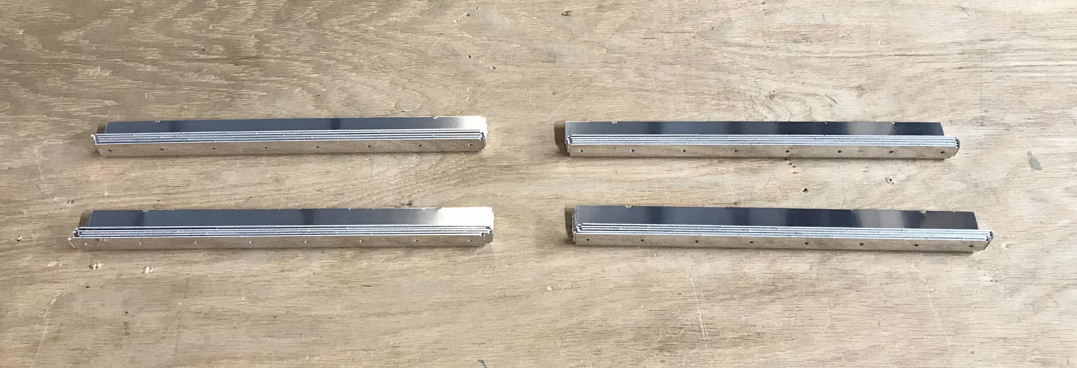
The T-00004 Tank Stiffeners are shown below in their “raw” form as they were when they arrived in the kit. They come connected in four long pieces of aluminum and need to be cut and trimmed into individual pieces. Each Wing will get 10 of these Stiffeners, so two strips are for the Right Wing and two strips are for the Left Wing. There are a total of 20 Stiffeners shown below.

After removing the blue plastic, I used my bandsaw to cut the pieces into individual pieces.....these are the four strips shown above.
After cutting them into 20 individual pieces, they had to be trimmed into their final shapes. The corners of each Stiffener had to be removed to form the angles you see below on each end. Again, I also used my bandsaw to remove the little “triangles” from the Stiffeners. (All 40 triangles are in the little pile.....whatever)!

The next step was to clean the edges, dimple the #40 holes, and scuff the bottom of the Flanges that will make contact with the Tank Skins (the Flanges with the dimples on them). After all that, here are the 20 completed T-00004 Tank Stiffeners. Since these Stiffeners will be installed on the inside of the Fuel Tanks, the will NOT be primed. However, I will treat them with Alumiprep and Alodine prior to final assembly.

NOW.....In Part 1, Roger and I prepared the T-1003B-R & -L Inboard Tank Ribs. However, I was not completely satisfied with our results and ordered two new Inboard Tank Ribs from Van’s. Now, two of the four VA-141 Finger Strainer Flanges (one in each Rib) already had corresponding holes in the Inboard Tank Ribs prepared by Van’s.....the other two have to be prepared by the builder. This is where my dissatisfaction comes from with the preparation of the Flanges/Ribs in Part 1. Below is my second attempt.....which turned out much better to my liking. In the picture below, the 3/4 inch hole and five #30 holes on the bottom left were the ones prepared by Van’s....the same arrangement on the top left were the one’s I prepared. To make this outcome better, I positioned the Finger Strainer Flange on the Inboard Tank Rib and then traced the Flange onto the Rib with a blue sharpie. By doing this, I was able to find the center of the enlarged 3/4 hole. Then the five #30 holes were Match-Drilled to the Rib. I was much happier with this result. I used the same method for Left and Right Inboard Tank Ribs.

Here you can see the orientation of the Finger Strainer Flange and the Inboard Tank Rib after being Match-Drilled #30.

Shown below are the completed T-1003B-R & -L Inboard Tank Ribs, two T-00005A Tank Stiffeners, two T-00005B Vent Line Clips, and 14 T-1012 Tank Attach Zees.

The 14 T-1012 Tank Attach Zees will be primed (because the are on the outside of the Fuel Tank) and were prepared with Alumiprep and Alodine. You can see the Zees getting their Alodine bath below.

After drying overnight, the 14 Tank Attach Zees were sprayed/primed with Akzo.

Then, 12 of the Attach Zees received 36 (three on each Zee) K-1000-3 nutplates. AN426AD3-3.5 rivets were used to attach the nutplates to the Zees.
