Saturday, September 15, 2018

Wings, Systems Routing (Part 4)

During today’s session, I focused on the last two “routings”.....the Wing Tip landing lights and the static lines for the Dynon Pitot Tube (heated with AOA).

To begin, pictured below are the Aeroled’s Aerosun VX landing/taxi/recognition lights designed for the RV line of aircraft.  These lights draw 60 watts of power and generate a combined 13,300 lumens of light.  The lights include a built-in wig-wag controller for a synchronized recognition light mode.  These are additional/optional lights that I have chosen to add to the my lighting system.  These lights will work in conjunction with the Aeroled Sunspot 36’s that will be installed in the outboard leading edge of each wing.

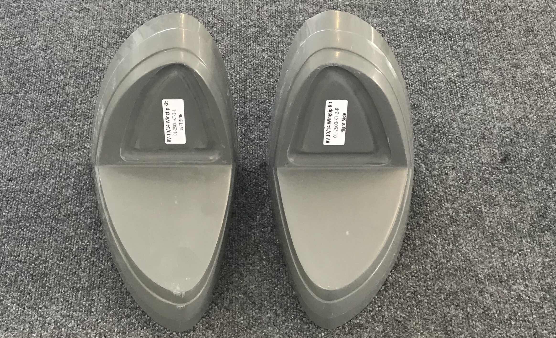
The fairings (known as a conversion kit) shown below were also ordered with the lights.  This conversion kit is required to enlarge the lighting cove to accept the Aerosun VX lights.  This conversion kit is required for the RV-10 and RV-14 if the Aerosun VX will be used.  (This installation will be covered at some point later when I complete the fairing work).
Here’s a video of the “extra” landing light wire run in the Right Wing.  (I will show the Left Wing static sine runs further down the post).


With the additional landing light wires run and completed, I started working on the Static Line runs.  My airplane will need/use three static lines.....
Blue tubing:  Airspeed (Dynon Pitot Tube)
White tubing:  Angle of Attach (AOA) (Dynon Pitot Tube)
Red tubing:  Static Ports 

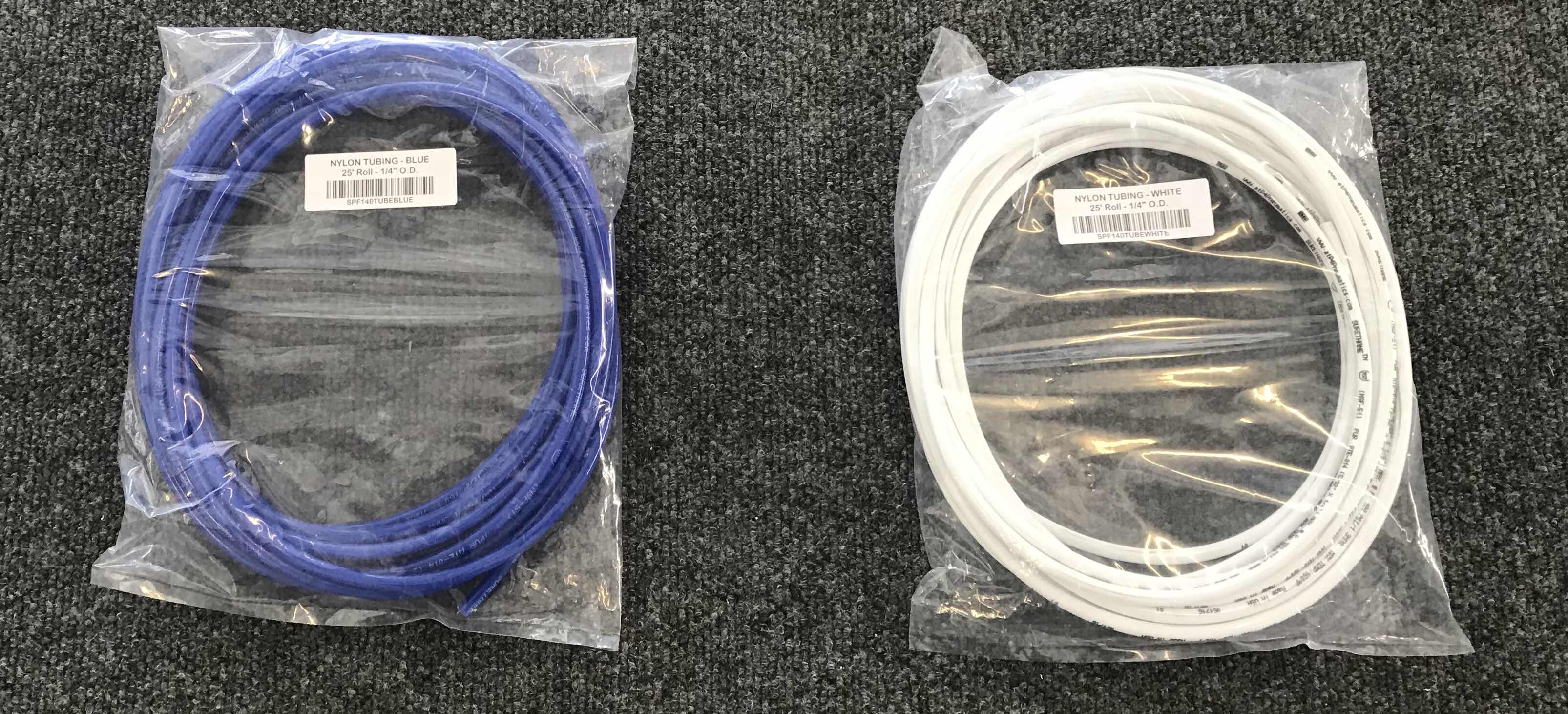
The blue and white nylon 1/4” O.D. tubing is shown in the packaging and the red is already installed in the Aft Fuselage (as shown below).  All three were ordered from Cleaveland Aircraft Tool.

Because I am adding the additional Wing Tip Lights and two Static Lines (Pitot and AOA), I had to “modify” four of the Left Wing Ribs.  When I was preparing the Ribs in an earlier section, I drilled 1/2” holes in them to allow for wire and tubing runs.  In the picture below, two of these holes are circled and have plastic grommets installed.  The bottom bundle of wires are for the leading edge landing light (Sunspot 36) and the position/strobe light (Pulsar NS90).  The two white wires are for the optional Aerosun VX landing lights.  The two holes that are circled are to be used for the Pitot static lines.  Since I’m using the Dynon Pitot tube with AOA, I will need to use two static lines.....and two static lines WILL NOT fit through the 1/2 hole.  I debated several different options, but ultimately decided to enlarge the holes on the four associated ribs.

The original holes were drilled to 1/2” and needed to be enlarged two steps on the unibit to 5/8”.  Shown here are the four holes I enlarged.  The holes were then deburred and treated with Alumiprep, Alodine, and Akzo Primer.

After the Akzo Primer dried, I installed these MS-35489-13 rubber grommets.....


.....and “tested” to ensure the proper fit.

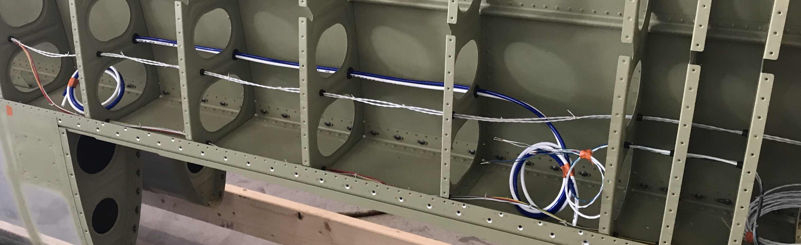
After the “test” fit I ran the tubing.  Here is a close up of the tubing installed in the Left Wing with showing the rubber grommets. 

This picture shows the final installation of the static tubing.  The plans called for the tubing to be cut to 8’ lengths.  I cut them to a little over 9’ just to make sure there is enough extra if it’s needed.
Lastly, here is a video showing the installed Aerosun VX wiring and blue/white static tubing.  You can also see the wiring for the ADAHRS, Sunspot 36, and NS90.

Section Complete

Tuesday, September 4, 2018

Wings, Bottom Wing Skins (Part 8)

In the previous post, I covered the dimpling of the Left and Right Inboard Bottom Skins.  Today’s session completed the dimpling on the W-00005-L & -R Outboard Bottom Skins.  I used the pneumatic hand squeezer to dimple all the holes that could be reached with my 3” in yoke.  All the remaining holes were dimpled using the DRDT-2. 

Pictured below is the Left Outboard Wing Skin.

Pictured below is the Right Outboard Wing Skin.

Sunday, September 2, 2018

Wings, Bottom Wing Skins (Part 7)


During today’s session, I dimpled the W-00004-L & -R Inboard Bottom Skins.  I used the pneumatic hand squeezer to dimple the holes that could be reached with my 3” yoke and the DRDT-2 for all the remaining holes.  Because both Inboard Skins are essentially identical and share the same rivet/dimple locations, I will only show the Left Bottom Skin in the pictures below.  Another reason for showing the Left Inboard Bottom Skin is because it has two very small differences compared to the Right Bottom Skin.  The two differences are:

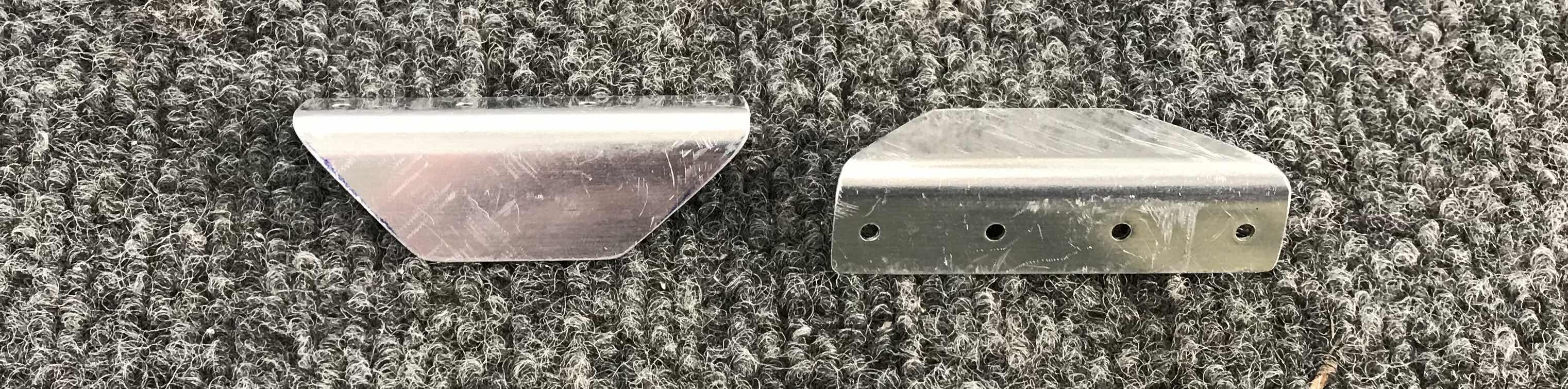
1.   These six rivet (and dimple) locations circled in black is where the W-00012E Mounting Zee will be installed for the ADAHRS Mount Bracket.  (The J-Stiffener will also be used for this bracket installation.  The preparation for the ADAHRS bracket mount is covered in Post #5 and the installation will be covered in future post).

2.  The small 1/4” hole next to the Access Panel.  This hole will be used later in the build for the outside air temperature probe.....I think.  This hole is located in the area where the ADAHRS will be installed, so it only makes sense for the temperature probe to be co-located in the same place.

This picture shows the opposite side of the Left Inboard Bottom Skin.

Sunday, August 26, 2018

Wings, Bottom Wing Skins (Part 6)

Work Completed on Saturday, August 25, 2018

I started this work session by dimpling the W-00009B Wing Box J-Stiffener - Short and W-00009A Wing Box J-Stiffener - Long.  Next, I started work on the Right Inboard Bottom Skin.  The first step was to match-drill #40 the W-1010R Inboard Wing Rib at all nutplate rivet hole locations in the Bottom Inboard Wing Skin (in the areas with vertical row of rivets in the picture below).  Then, the nutplate screw hole locations were final-drilled to #19.  


Lastly, I deburred all the #19 and #40 holes.


—————————————————————————————————————————————

Work Completed on Sunday, August 26, 2018
I started tonight’s session by completing the edge work on the Left Inboard Wing Skin.  Once completed that was completed, I moved on to the W-00005-L & -R Bottom Outboard Wing Skins.  To complete the Outboard Skins, the following steps were completed:

1.  Final-Drilled the #19 the screw holes in the Access Plate Attach locations 
2.  Deburred all the #40 and #19 holes
3.  Cleaned all the edges 

In the pictures below, I have clecoed the Inboard and Outboard Wing Skins in place on their respective wing (Right Wing in the first picture and the Left Wing in the second).  The next step is to “sand” or trim forward areas where the two Skins overlap.  This will be done in a similar fashion as when the Top Wing Skins were prepared (Parts 11 and 12).

Right Wing.....

Left Wing.....


Tuesday, August 21, 2018

Wings, Fuel Tanks (Part 24)

Tonight, Jeff and I were able to complete the Wing Rib installation during this session.  The first step was to rivet (and Proseal) the Tank Attach Bracket to the Tank Skin as shown below.

Then, rivets the Tank Inboard Rib to the Skin.

And finally, set the six AN470AD4-5 rivets between the Tank Inboard Rib - FWD, Tank Inboard Rib - AFT, and the Tank Attach Bracket.  Below are several pictures of the final product.


Monday, August 20, 2018

Wings, Bottom Wing Skins (Part 5)

To begin this section, I had to cleco the W-00009B Wing Box J-Stiffener - Short to the Inboard Bottom Skin.  However, I wanted to make I was clecoing it to the appropriate location on the Skin.  So, in the picture below, you can see parts off the Bottom Skin, J-Stiffener - Short (on the right), and J-Stiffener - Long (on the left).  

Once I verified the proper location for J-Stiffener, I clecoed it to the Inboard Bottom Skin as shown below.

Now, it’s time for the ADAHRS mounting bracket. So, I’m supposed to make the my mounting bracket look the same as the plans excerpt below.  First, the W-00012E Mounting Zee had to be clecoed to the W-00012A Mounting Plate.  Then, the Mounting Zee and Mounting Plate is clecoed to the Bottom Inboard Wing Skin.  Lastly, the five holes common to the Mounting Plate and J-Stiffener had to be match-drilled #30.

Here is what everything looked like when it was finished.  The five copper clecos at the bottom of the picture were the locations the holes were Match-Drilled.  I used the two blue clips to make sure the distance between the Mounting Plate and J-Stiffener remained constant.

Finally, I deburred and dimpled the #40 holes in the J-Stiffeners (Long and Short).

Saturday, August 18, 2018

Wings, Fuel Tanks (Part 23)

Tonight’s session concentrated on installing the Fuel Vent Line as shown in the plans excerpt below.  The kit supplied 25’ of coiled AT0-032x1/4 soft aluminum tubing.  A piece of the tubing was cut to a length of 54 1/16”.  I then “massaged” the tubing until it was “straight” and hand bent it at the two locations shown below.

 
The video shows the completed static line.  

Friday, August 17, 2018

Wings, Bottom Wing Skins (Part 4)

In Part 3, I riveted the Aileron and Flap Gap Fairings to the Right Wing.  During this session, I riveted the Aileron and Flap Gap Fairings to the Left Wing.  The second video shows the competed rivet installation.  


Thursday, August 16, 2018

Wings, Bottom Wing Skins (Part 3)

In Part 2, the two Aileron Gap Fairings and two Flap Gap Fairings were clecoed into place on the Left and Right Wings.  During this session, I started installing the required rivets and decided to start with the Right Wing.  

The last video below shows the completed rivet installation on the Right Wing Aileron and Flap Gap Fairings.  The Gap Fairings are installed to the Wings using four different sized rivets:

-AN426AD3-3.6
-AN426AD4-8
-AN470AD4-4
-AN470AD4-5


Wings, Fuel Tanks (Part 22)

My buddy Jeff was available to help with the Fuel Tanks, so during this session we started the installation of the Fuel Tank Ribs.  

*****Confession To Make*****

The picture below is from the build plans page 18-05.  If you look at Figure 3:  Tank Skin & Ribs Subassembly, it shows the proper locations and orientation of the Tank Ribs.  With the exception of Rib #1, all Tank Ribs are installed with the Flanges facing left (or toward the fuel filler cap) for the Left Fuel Tank.  Additionally, I have numbered each Tank Rib, inboard to outboard, from #1 thru #7 for easier identification.

Pictured below, is my Left Fuel Tank with the Tank Ribs riveted into plane and prosealed.  I numbered the same Ribs below to correspond with the numbered Ribs in the Plans above (except for Rib #1 which you can’t see).  If you will notice in the picture below, Ribs 3-6 are NOT oriented as shown in the plans above.  I mistakenly used Ribs that were apparently meant for the Right Fuel Tank and the Flanges face AWAY from from the filler cap. 

Here is another angle of the Left Fuel Tank.

I clecoed the Tank Attach Bracket Subassembly, Tank Inboard Rib-Aft, Tank Baffle, and Tank Attach Zees to my tank above.....ALL THE HOLES LINED UP.

So, during that OH SH*T moment, I started to figure out what I was going to do.  After all the “I can’t believe I did that” comments to myself, I decided to email Van’s for some professional advice.  In my email to Van’s, I described my “problem” and included the pictures above.  Mitch Lock very quickly responded to my questions regarding my tank “problem”.....I even got a opinion from Mr. Van himself.

So, I was advised that if all the holes lined up properly among the pieces I mentioned above....BUILD ON!  My additional concern was wether the orientation of the Tank Ribs was for any structural reasons.  This is where Mr. Van comes in.....he can see no structural reason that the orientation makes a difference.

Good enough for me.....so, my mind is at ease!

As a result, I will construct the Right Fuel Tank with the Ribs oriented in the same directions as the Left.

Wednesday, August 15, 2018

Wings, Bottom Wing Skins (Part 2)

To start today’s session, I treated the Aileron Gap Fairings (x2) and Flap Gap Fairings (x2) with Alumiprep and Alodine.  Because of their size, I used my spray bottles, grey Scotchbrite, and foam brushes.  After the pieces had thoroughly dried, I primed them with Akzo primer. 

The next step in the plans was to rivet the Flap Gap Stiffeners to the Flap Gap Fairings.  They are attached with four AN426AD3-3.5 rivets.  The two pictures below show one of the Stiffeners attached.....top picture the manufactured head and the bottom picture the shop head.  I set all eight rivets with the pneumatic squeezer.


After riveting the Stiffeners, I clecoed all four Fairings in place on the Left and Right Wing Rear Spars and Top Skins.  The picture below shows the Left Wing with the Flap Gap Fairing clecoed into place.....silver #40 clecos to the Top Skin and the copper #30 clecos to the Rear Spar.  The Fairing will be attached using 93 rivets.

This picture shows the Aileron Gap Fairing clecoed into place.  This Fairing will be attached using 69 rivets.

Tuesday, August 14, 2018

Wings, Bottom Wing Skins (Part 1)


Since I’m putting Section 19 on “pause” until I get a pitot tube.....guess what?  I started Section 20.

This first step in this section is to prepare the W-1021B Flap Gap Stiffeners.  The Stiffeners come in one piece (shown below).....

and has to be separated into two individual Stiffeners as shown in the plans excerpt below.

After all the cutting, trimming, and sanding......here are the two individual Stiffeners.  The four #40 holes on each Stiffeners were then final-drilled and dimpled and the edge work was completed.

Pictured below are the W-00011-L & -R Aileron Gap Fairings (the two shorter Fairings) and the W-00010-L & -R Flap Gap Fairings (the two longer Fairings).  All four of these pieces needed the following work:
1.  Deburr all the holes (#30’s and #40’s)
2.Dimple all the #40 holes
3.  Dimple the six most inboard #30 holes on the Flap Gap Fairings
4.  Clean the edges


All four steps listed above have been completed and they are ready for Alumiprep, Alodine, and Akzo Primer.

Friday, August 10, 2018

Wings, Systems Routing (Part 3)

During today’s session, I ran the wiring for the WH-00012-ADAHRS in the Left Wing.

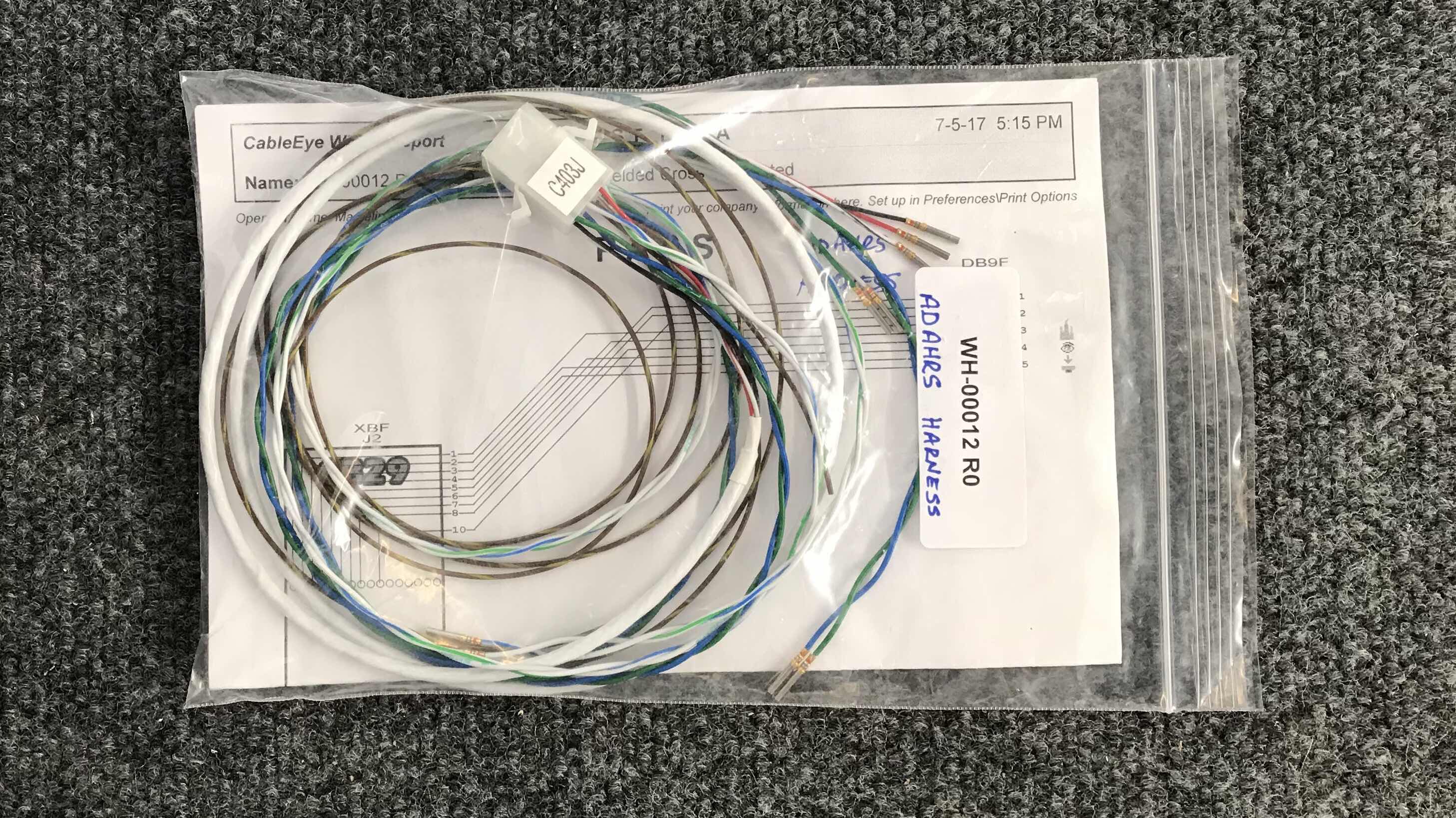
Pictured below is the wires and harness in the packaging from Van’s.

Here is the initial installation of the wires.  The far left side of the wires are coiled (I used the orange tape) for later connection to whatever ADAHRS system I choose.  (I plan on using Dynon Avionics).

So, that is all the wire runs for the Systems Routings (well, almost).  I still have to run tubing for the pitot tube.  However, I am waiting for the Dynon pitot tube to arrive.  Once it does, I will install it and complete this section.  I will be using a heated Dynon pitot tube with AOA.

So, I’ll “pause” Section 19 until I start the Pitot Tube install.

Thursday, August 9, 2018

Wings, Systems Routing (Part 2)

Not much excitement today.....I ran the wiring for the WH-00013-AP Servo during this session.

Tuesday, August 7, 2018

Wings, Systems Routing (Part 1)


I’m currently waiting on my friend Jeff to help me finish the Fuel Tanks.  I will definitely need his assistance to install and rivet the Ribs (with the Proseal).  So, in order to keep moving forward, I’ve decided to start on the Wing Systems Routing section.  

Below, are the Wing Tip Lighting Harnesses for the Left Wing (top picture) and Right Wing (bottom picture)


The first step is two label the Harnesses (C400P and C401J) appropriately as shown below.  To do this, I just used a regular label making machine, so nothing special here.

The two pictures below show the Wing Tip Lighting wire runs for the Left Wing.  The first picture shows the mid-wing area where the wires “shift” from one row of bushings to another.  The second picture shows the Wing Tip where the wires run to two different locations.....to the Wings Tips for navigational lights and strobes and through the spar for the Landing Light.  


The two pictures below show the same Wing Tip Lighting wire runs and locations, but for the Right Wing.


Lastly, here is the origin of the Wing Tip Harnesses for the Left Wing (on the left) and Right Wing (on the right).  The black and white wires under the orange tape will be installed/connected once the Fuel Tanks are completed and installed on the Wings.  The white wire will be run through the small bushing in the Main Spars to the Fuel Level Senders and the black wire will be a ground connected to the first Wing Ribs.

I will obviously need to “clean up” the wire runs, but will do that at the end to make sure all the wires are installed properly.